VIERLING ECOTEL VTMpro User manual

ECOTEL
®
VTMpro
Manual
Issue 1.1
VIERLING Communications GmbH
70463.201/20 - 1.1 – 20050630

ECOTEL®VTMpro 2005-06-08 Page 2
Table of Contents
1.
Definition ...........................................................................................................5
2.
Quick Start.........................................................................................................6
2.1 Components.......................................................................................................6
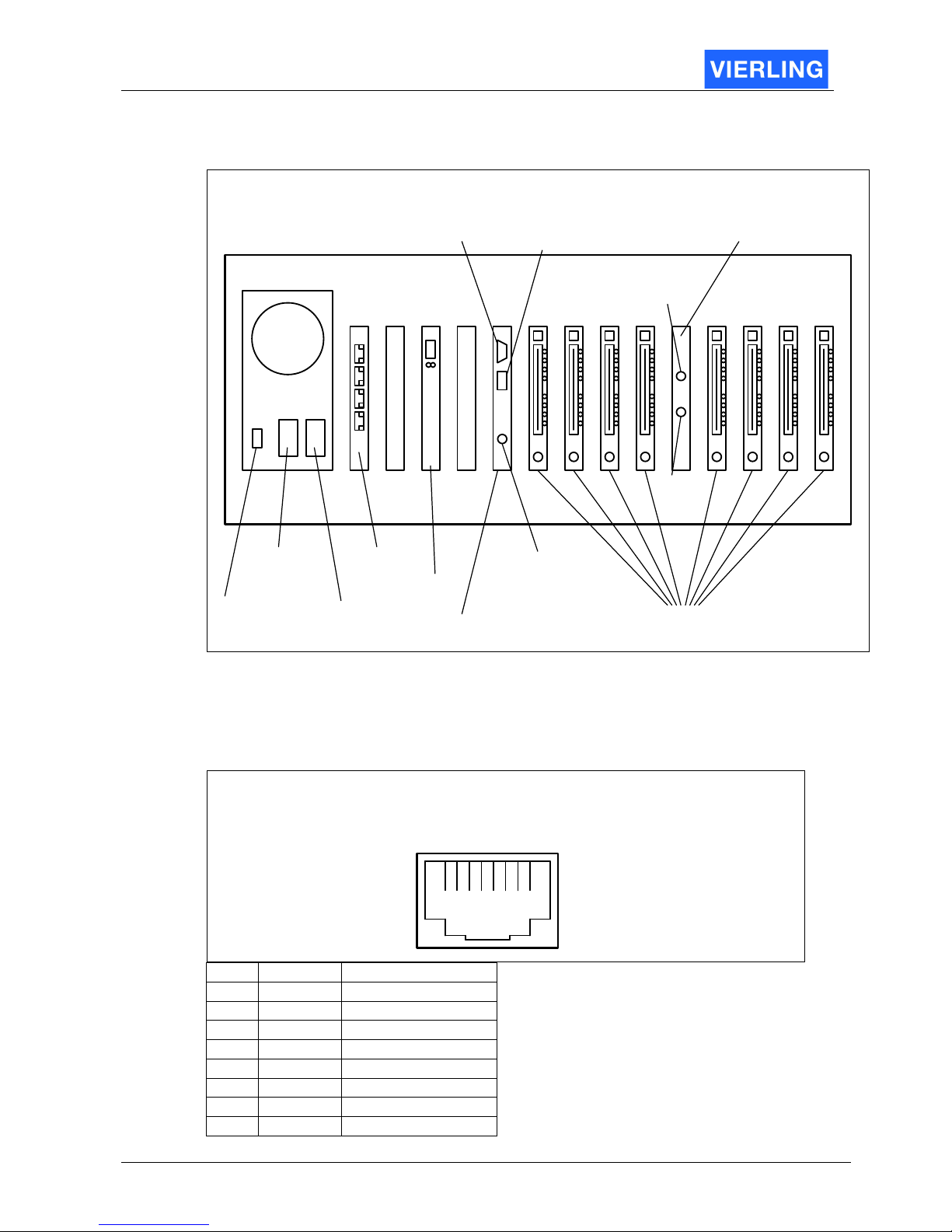
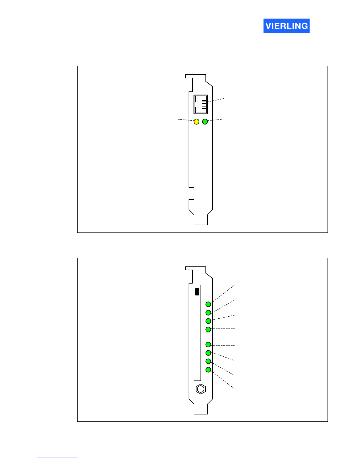
2.2 ECOTEL® VTMpro front view ............................................................................6
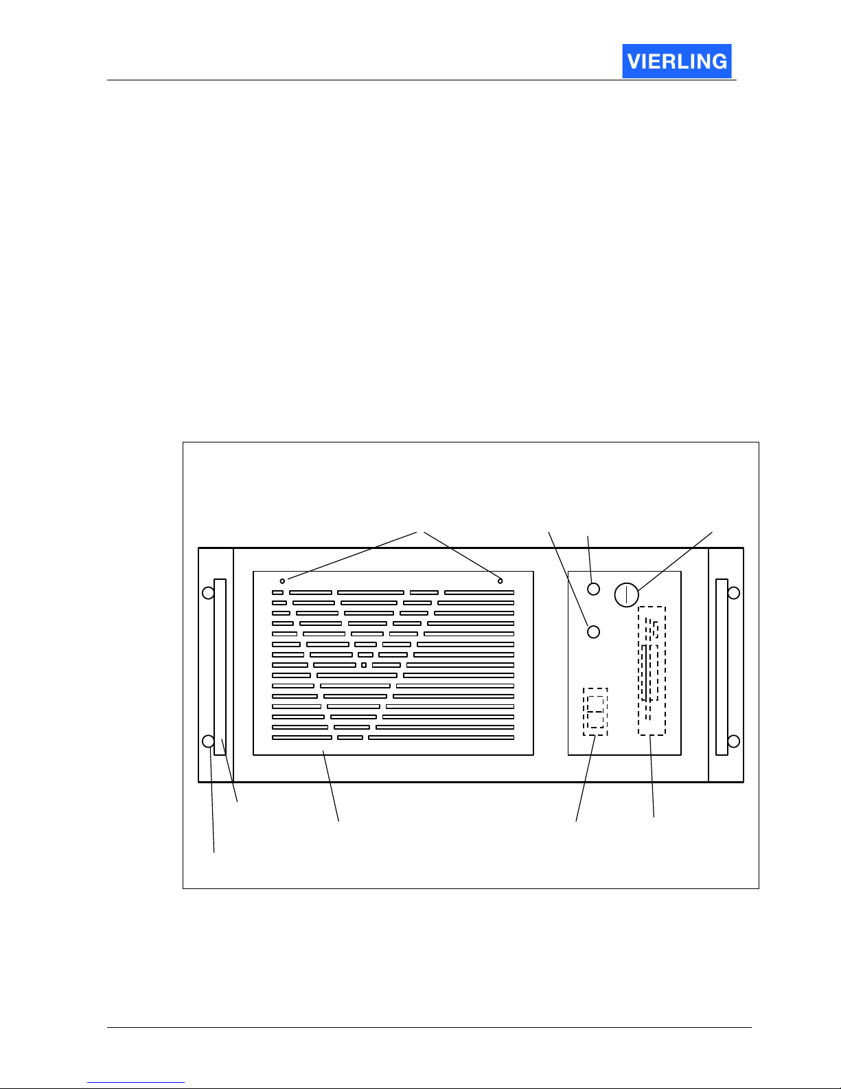
2.3 ECOTEL® VTMpro back view............................................................................7
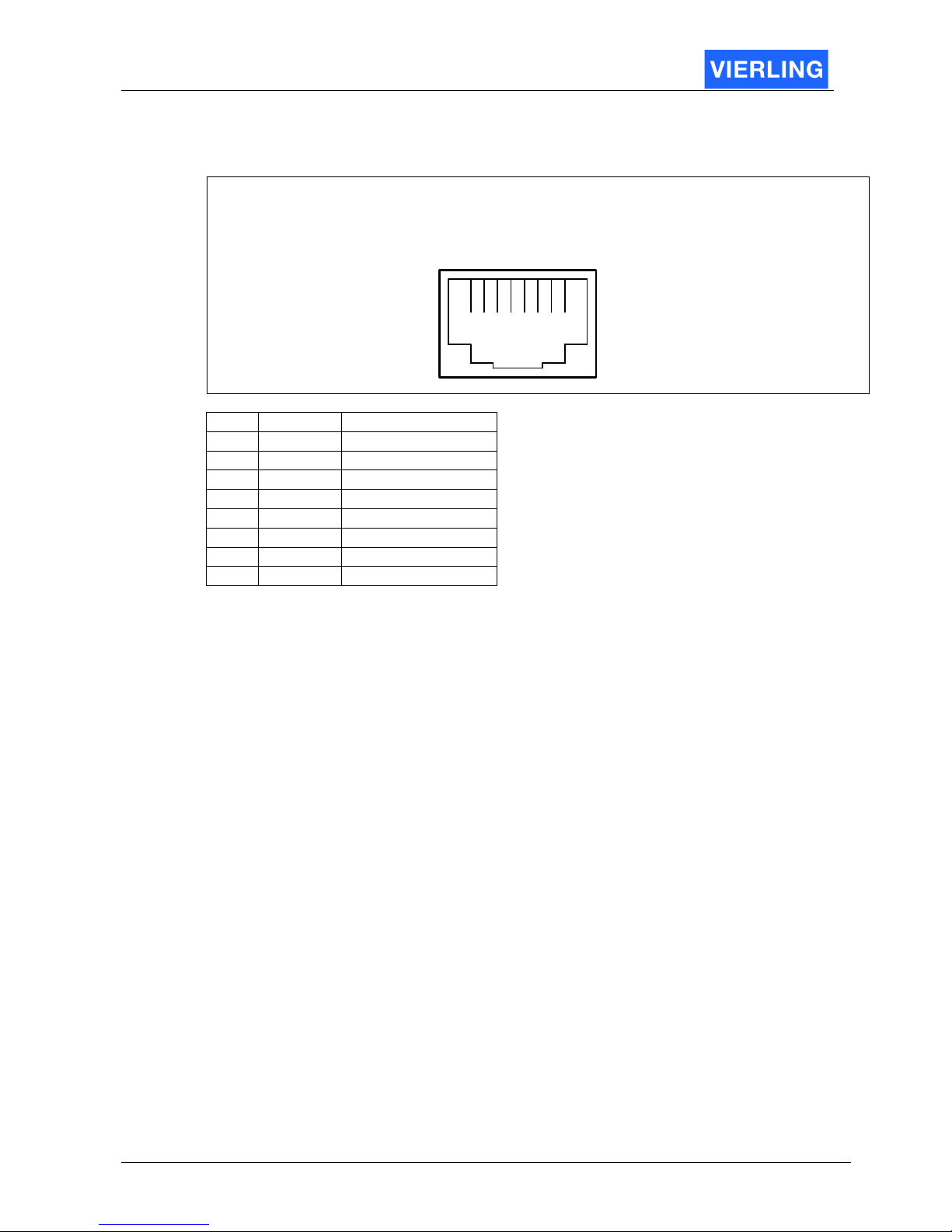
2.4 Pinning of connectors......................................................................................... 7
2.4.1
Ethernet for LAN and VoIP .........................................................................7
2.4.2
E1/T1 .........................................................................................................8
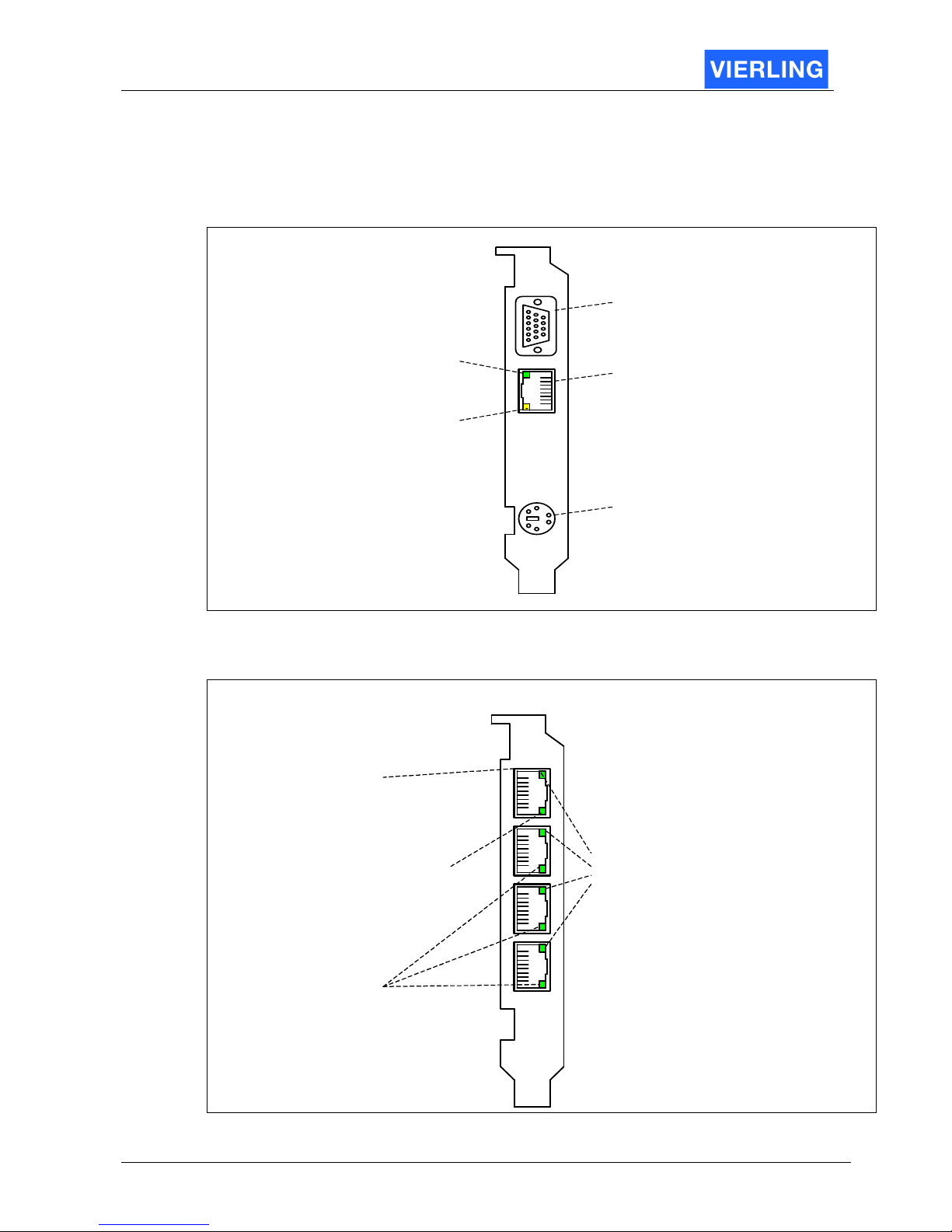
2.5 Interpreting of board connectors and status LEDs..............................................9
2.5.1
Mainboard ..................................................................................................9
2.5.2
E1/T1 .........................................................................................................9
2.5.3
VoIP .........................................................................................................10
2.5.4
GSM-Card ................................................................................................10
2.6 Getting started ................................................................................................. 11
3.
Introduction......................................................................................................12
3.1
General ............................................................................................................ 12
3.2
Controlling the ECOTEL
®
VTMpro local and LINUX environment..................... 12
3.3
Controlling the ECOTEL
®
VTMpro from WINDOWS environment .................... 12
4.
Softwareinstallation .........................................................................................13
5.
ServiceGear – ECOTEL
®
VTMpro administration ............................................14
6.
Setup network interface ...................................................................................16
6.1
Default Configuration ....................................................................................... 16
6.2
Changing network configuration ....................................................................... 16
7.
Connect to Remote Gateway...........................................................................19
8.
ServiceGear - Gateway ...................................................................................20
8.1
Statusline ......................................................................................................... 20
8.1.1
File ...........................................................................................................20
8.1.2
Gateway ...................................................................................................20
8.1.3
Channels ..................................................................................................21
8.1.4
Routing.....................................................................................................21
8.1.5
Call Generator..........................................................................................21
8.1.6
Help..........................................................................................................21
8.2
Horizontal Icon Bar........................................................................................... 22
8.3
Vertical Icon Bar............................................................................................... 22
9.
Gateway ..........................................................................................................24
9.1
Gateway........................................................................................................... 24
9.2
Configuration.................................................................................................... 25
9.3
License ............................................................................................................ 25
10.
Channels .........................................................................................................26
10.1
Email................................................................................................................ 27
10.1.1
General ....................................................................................................27
10.1.2
Details ......................................................................................................27
10.1.3
Usage Step by step ..................................................................................28
10.2
VoIP................................................................................................................. 30
10.2.1
Information ...............................................................................................32
10.2.2
License Key..............................................................................................32
10.2.3
Board Configuration..................................................................................32
10.2.4
VoIP Configuration ...................................................................................33
10.2.5
Firmware ..................................................................................................33

ECOTEL®VTMpro 2005-06-08 Page 3
10.3
GSM................................................................................................................. 33
10.3.1
Board Control Panel .................................................................................33
10.3.2
Channel Control Panel .............................................................................37
10.4
ISDN ................................................................................................................ 43
10.4.1
Information ...............................................................................................43
10.4.2
Configuration............................................................................................44
10.5
Simcontrol........................................................................................................ 45
10.5.1
Overview ..................................................................................................45
10.5.2
Functions in detail ....................................................................................45
10.6
SMC Sim Management Center......................................................................... 46
10.6.1
General ....................................................................................................46
10.6.2
Local SIMs ...............................................................................................47
10.6.3
SIM Groups ..............................................................................................50
11.
Routing............................................................................................................53
11.1
Establishing a new routing step by step ........................................................... 53
11.2
Routing features in detail.................................................................................. 54
11.2.1
Philosophy................................................................................................54
11.2.2
Routings...................................................................................................54
11.2.3
Port Routing List.......................................................................................55
12.
Call Generator .................................................................................................65
12.1
Overview.......................................................................................................... 65
12.2
Functions in details .......................................................................................... 67
12.2.1
Horizontal Icon bar ...................................................................................67
12.2.2
Elements from main view..........................................................................67
13.
Statistics..........................................................................................................68
14.
Connections ....................................................................................................70
14.1
Connections view ............................................................................................. 70
14.2
Logfiles and configuration ................................................................................ 71
15.
Online Trace....................................................................................................72
16.
Layer 2&3 Trace..............................................................................................73
16.1
Offline trace and settings.................................................................................. 73
16.1.1
Trace Mask ..............................................................................................73
16.1.2
Offline Trace.............................................................................................74
16.2
Online trace...................................................................................................... 74
17.
CDR – Call Data Records................................................................................75
17.1
General ............................................................................................................ 75
17.2
Format ............................................................................................................. 75
18.
Tools ...............................................................................................................76
18.1
Secure Shell-Tool-PuTTY ................................................................................ 76
18.2
Secure Copy-Tool-PSCP ................................................................................. 76

ECOTEL®VTMpro 2005-06-08 Page 4

ECOTEL®VTMpro 2005-06-08 Page 5
1. Definition
ECOTEL
®
VTMpro is a multichannel gateway from the VIERLING gateway family that
provides the connection between fixed and mobile network of up to 32 channels. It
supports 4 ports with 30 channels ISDN PRI E1/T1, 4 ports with 2 channels ISDN 4xBRI
E1/T1, 1 Port/30 channels VoIP/H.323 interface at the fixed and up to 32 channels GSM
850/1900 and/or GSM 900//1800 MHz at the mobile network interface. The ECOTEL
®
VTMpro has a sophisticated routing software that can be controlled local or remote by a
graphical user interface. The gateway provides furthermore versatile statistics, trace and
monitorfunctions. Call data files for billing can also be created and saved.

ECOTEL®VTMpro 2005-06-08 Page 6
2. Quick Start
2.1
Components
ECOTEL
®
VTMpro is optionally equipped with different boards. The boards can be
accessed by the back of the housing. The available boards are (detailed description later
in the manual):
•
Mainboard
•
VoIP card
•
ISDN PRI card
•
ISDN BRI card
•
GSM card
•
Antenna splitter card
The mainboard is mandatory all other boards are optionally. Normally ECOTEL
®
VTMpro
is equipped with one of the boards VoIP, ISDN PRI or ISDN BRI and one to eight GSM
cards.
2.2
ECOTEL
®
VTMpro front view
Fix point for
rack mounting
VTMpro front:
Grip for
carrying
Cover for
air filter
Switch
Floppy
LED HarddiscLED Power
Lock
Screw for removing air filter

ECOTEL®VTMpro 2005-06-08 Page 7
2.3
ECOTEL
®
VTMpro back view
Power
supply
Power for
monitor
Main
switch
ISDN
4xE1/T1
1
2
3
4
VoIP
Mainboard
Keyboard/Mouse
(via adapter)
GSM-Card
1
2
3
4
5
6
7
8
Antenna
GSM
2 to 8
GSM
1 to 4
VTMpro back view:
Monitor
LAN
(for remote access)
2.4
Pinning of connectors
2.4.1 Ethernet for LAN and VoIP
Ethernet LAN and VoIP port (RJ
-
45 socket):
1 2 3 4 5 6 7 8
Pin Signal Description
1 TX + Transmit Data
2 TX - Transmit Data
3 RX + Receive Data
4 Res Reserved
5 Res Reserved
6 RX - Receive Data
7 Res Reserved
8 Res Reserved

ECOTEL®VTMpro 2005-06-08 Page 8
2.4.2 E1/T1
Ethernet LAN and VoIP port (RJ-45 socket):
1 2 3 4 5 6 7 8
Pin Signal Description
1 RX + Receive Data
2 RX - Receive Data
3 Res Reserved
4 TX+ Transmit Data
5 TX- Transmit Data
6 Res Reserved
7 Res Reserved
8 Res Reserved

ECOTEL®VTMpro 2005-06-08 Page 9
2.5
Interpreting of board connectors and status LEDs
2.5.1 Mainboard
M ainBoard :
Receive D ata (yello w )
Lights when data is
received
LAN
RJ45 socket
Link (green)
Lights when ethernet
connection is on
Monitor
PS/2 Console
Keyboard/Mouse
via adapter
2.5.2 E1/T1
E1/T1:
L1 Status LED
Off: L1 not active
On: L1 active
Status for each port
Firmware Status LED
• Flashing fast (1Hz):
Firmware not running
• Flashing slow (1/2 Hz):
Firmware running
Status for all ports
No meaning!
RJ45 socket
1
2
3
4

ECOTEL®VTMpro 2005-06-08 Page 10
2.5.3 VoIP
VoIP:
Receive Data (yellow)
Lights when data is
received
RJ45 socket
Link (green)
Lights when ethernet
connection is on
2.5.4 GSM-Card
GSM-Card:
SIM:
Flashing: Registering in progress
On: Registered
1
2
3
4
1
2
3
4
GSM:
Flashing: Call establishing
On: Call active
Ch 1
Ch 2
Ch 3
Ch 4
Ch 1
Ch 2
Ch 3
Ch 4
Ant
S
I
M
G
S
M

ECOTEL®VTMpro 2005-06-08 Page 11
2.6
Getting started
To get the ECOTEL
®
VTMpro started follow this instruction:
•
Remove VTMpro from the box
•
Plug in the power cable shipped with
•
Connect the power cable with power supply: 110-240 Volt/50-60 Hz
•
Plug in the adapter for keyboard and mouse.
•
Connect a keyboard, mouse and monitor to the adapter. The console can be
removed after very basic settings.
•
Optionally plug in the ethernet cable in to the RJ45 socket of the main board to
control the ECOTEL
®
VTMpro by remote
•
Optionally connect the VoIP card with the LAN
•
Optionally connect one or more sockets of the E1/T1 card to a switch/pbx or
router.
•
Connect an antenna to the “Antenna” slot
•
Assemble the SIM carrier within the GSM cards with SIMs
•
Switch on the main switch at the power supply
•
Press the switch below the front cover
•
The ECOTEL
®
VTMpro will start up
•
Follow the instructions in the “ECOTEL
®
VTMpro Software part
•
To switch off press the button under the front cover for at least 5 seconds, or shut
it down over the “Start” menu via terminal.

ECOTEL®VTMpro 2005-06-08 Page 12
3. Introduction
3.1
General
ECOTEL
®
VTMpro is a LINUX based gateway for interconnection between fixed and
mobile network. The embedded controlling intelligence runs without a face within the
LINUX system. The controlling intelligence further in context, also called as gateway,
routing engine or LCR, has a network interface for remote controlling. There is a GUI
available using this interface. The GUI has two compilations: One for LINUX and one for
WINDOWS. The LINUX version is also installed on the ECOTEL
®
VTMpro and can be
started there to control the local gateway or the gateway from a different ECOTEL
®
VTMpro within the network.
3.2
Controlling the ECOTEL
®
VTMpro local and LINUX environment
To start the ServiceGear on local ECOTEL
®
VTMpro follow the instruction:
1. Connect a console (Monitor, Keyboard Mouse) to the gateway. For connecting the
keyboard and mouse the delivered adapter must be used
2. After the boot sequence login with following default parameters:
User: vierling
Password: vierling
3. A gear-wheel icon “ECOTEL
®
VTMpro ServiceGear” appears on the desktop.
Click ion this symbol to start the maintenance GUI.
4. Choose the gateway symbol from the vertical icon bar and press connect. By
default the local machine can be accessed by the name “localhost”, no password
is given.
A
TTENTION
For security reason the password should be changed.
5. To connect to the local gateway press the “Connect” button.
3.3
Controlling the ECOTEL
®
VTMpro from WINDOWS environment
To control the ECOTEL
®
VTMpro from WINDOW the specific software must be installed,
which is explained in next chapter.

ECOTEL®VTMpro 2005-06-08 Page 13
4. Softwareinstallation
Start the self inflating installing routine by double clicking on the following symbol from the
CD:
After the start follow the instructions!
The ServiceGear needs .Net framework from Microsoft. This framework is already
installed on newer Windows installations. If not the ECOTEL
®
VTMpro installer will cancel
the installation and advice to install the framework first. It gives also the option to do this
immediately by providing this installation also by the ECOTEL
®
VTMpro installer. After the
framework installation the ECOTEL
®
VTMpro ServiceGear installation can be started
again.

ECOTEL®VTMpro 2005-06-08 Page 14
5. ServiceGear – ECOTEL®VTMpro administration
After the successful installation the ECOTEL
®
VTMpro ServiceGear can be started by
pressing the following icon on the desktop:
The administration area on group level appears.
The ServiceGear provides the possibility to administrate groups of ECOTEL
®
VTMpro e.g.
one group for each customer. (The screen shot shows already established groups).
To establish a new group the following steps must be done:
•
Select Edit->New Group or the empty sheet symbol.
•
Enter a group name at the field “Group Name”.
•
The other settings are for use of an external Sim Server und must not be changed.
•
Create the new group by pressing O.K..
The group can now bear many ECOTEL
®
VTMpro links. To apply a new ECOTEL
®
VTMpro to the new group double click on the specific group symbol within the ECOTEL
®
VTMpro Service Gear. The following Service Gear Group window appears:

ECOTEL®VTMpro 2005-06-08 Page 15
To enter a new ECOTEL
®
VTMpro the following steps must be done:
•
Click into a new line
•
Press the “Pencil” symbol button from the menu to leave read only modus. Enter
the following settings:
Attribut: Description:
Name: The ECOTEL
®
VTMpro can be given a individual name
Location The ECOTEL
®
VTMpro can be given an arbitrary optional label for the
physical location of the gateway.
Address The address must be mandatory given in form of a known name within
a network or a IP address.
Port The port the ServiceGear communicates with VTMpro. May normally
not be changed.
Password
Enter a valid password for the specific VTMpro. The default password
is: NeuNeu
Type Changes optionally the type of the Gateway and the ServiceGear to
start, because the administration is universal usable for other gateway
types.
•
Confirm the settings by pressing the “Pencil” symbol again
•
Select the ECOTEL
®
VTMpro to administrate the list and press the “GUI” symbol
beside the pencil to start ServiceGear for the VTMpro. The remote maintenance
will start with the correct items. Alternatively the ServiceGear gateway can be
started manually and the necessary address and password can be entered by
hand. See the following chapter:

ECOTEL®VTMpro 2005-06-08 Page 16
6. Setup network interface
ECOTEL
®
VTMpro can be administrated by remote via TCP/IP connection. Therefore
ECOTEL
®
VTMpro and the remote ServiceGear must be setup properly.
6.1
Default Configuration
The delivered default configuration of the network interface is setup to a static IP address,
as follows:
172.16.8.16
To reach the ECOTEL
®
VTMpro with the remote gear there are two possibilities of setup:
1. Set the ECOTEL
®
VTMpro IP configuration as default and configure the remote
desktop to the value. This can be done anyway by a local connection between
ECOTEL
®
VTMpro and the remote host by using a cross connect LAN cable.
Otherwise the ECOTEL
®
VTMpro must be integrated into a existing network with
this static IP address. For security reason it is recommended to ask your network
administrator!
2. Change the IP interface of ECOTEL
®
VTMpro to DHCP or to a static IP address
given by your network administrator. To change the IP interface the steps in the
following chapter must be done!
6.2
Changing network configuration
1. Start the ECOTEL
®
VTMpro and wait until the login screen appears
2. Login with the following parameters:
Login: vierling
Password: U2xK3te8
3. Wait until the desktop is loaded completely
4. Click on the “Start Applications” button in the left bottom corner
5. Chose from the appearing menu the System -> YaST2 configuration tool:
6. To make changes on system infrastructure the root password must be entered:
Password: gR76aLaB

ECOTEL®VTMpro 2005-06-08 Page 17
Confirm with OK.
Hint: Enter the password
7. Choose Network Devices ->Network card from the appearing menu:
8. Choose “Change...” in the right bottom corner:
9. Make sure that the “eth0” device is selected and press “Edit” button in the middle

ECOTEL®VTMpro 2005-06-08 Page 18
10. Select
- Automatic address setup (via DHCP) if there is a DHCP server available in the
network to get a dynamic IP address assigned to the ECOTEL
®
VTMpro name.
The ECOTEL
®
VTMpro default name is: rittal
- Or Static address setup for selecting or changing the default IP address.
Configure also the Subnet mask according to your network administrator.
Click on the “Next” button to confirm the settings
11. Finish the network configuration by pressing “Finish” at the screenshot from item 9
to close the settings.
12. Close the Yast control center by pressing “close”
13. Now ECOTEL
®
VTMpro settings are valid and it is reachable with the new
address.

ECOTEL®VTMpro 2005-06-08 Page 19
7. Connect to Remote Gateway
To connect the ECOTEL
®
VTMpro choose from the left row the item “Gateway” and enter
the individual IP address into the field “Host” on the appearing fields. The predefined port
in the field “Port” normally has not to be changed. When you have entered the correct IP
address and pressed the button “Connect” you will be connected to the VTMpro. The
connection is confirmed by the status line in the left bottom corner of the window. If there
is a connection established the status is “connected” otherwise it is “idle” (compare to the
next picture). By the way you can observe the amount of data transferred between the
application on the ECOTEL
®
VTMpro and the computer the ServiceGear is hosted.
If the following screen appears you get a hint that you use different versions between the
application on the ECOTEL
®
VTMpro and the ServiceGear on your host. A version
conflict can happen, but normally the ServiceGear should be compatible until a certain
degree to former ECOTEL
®
VTMpro applications. You can connect by pressing the
“Connect Anyway” button.
After a successful connection the following part of the right screen part now carries valid
data:
This box shows license information. The ECOTEL
®
VTMpro may be restricted to a limited
lifetime. If lifetime has expired ECOTEL
®
VTMpro can not be further used. The “Valid”
field shows if ECOTEL
®
VTMpro can be still used or not. In case of expiration you can
load a valid license file to the system by using the function “Upload License”. Contact
VIERLING Communications support how to get such a license file. The lifetime is
separated in two categories:
•
Expiration: The ECOTEL
®
VTMpro runs unlimited until this date. After this date the
ECOTEL
®
VTMpro is unusable.
•
Runtime: The ECOTEL
®
VTMpro runs as long as the amount of entered hours in
the dedicated field. After expiration the ECOTEL
®
VTMpro is unusable. Only the
active time is counted. The idle time is ignored.

ECOTEL®VTMpro 2005-06-08 Page 20
8. ServiceGear - Gateway
After starting the program “ECOTEL
®
VTMpro ServiceGear Gateway” you will see the
above screen. The screen contains different parts, explained as follows:
8.1
Statusline
The statusline contains different menu items:
8.1.1 File
Attribut: Description:
Quit: Closes ECOTEL
®
VTMpro ServiceGear Gateway
8.1.2 Gateway
Attribut: Description:
Connect: Connects to remote gateway. Same function like the button on the
appearing screen after choosing the “Gateway” item from the vertical icon
bar.
Disconnect: Closes a connection between the ServiceGear and the gateway.
Restart: Restarts the application on the gateway. The connection to the
ServiceGear closes automatically. A new connection is possible when the
application on the ECOTEL
®
VTMpro has rebootet.
Table of contents
Popular Gateway manuals by other brands

NetWave
NetWave NW8 Installation and operation manual

Lucent Technologies
Lucent Technologies PacketStar PSAX 1000 user guide

Moxa Technologies
Moxa Technologies UC-8580 Series Quick installation guide

ExpertDAQ
ExpertDAQ EX9486C-W-MTCP Operation manual

RTA
RTA 460ECPS-NNA4 Product user guide

PipeBurst Pro
PipeBurst Pro RS500 Device user manual