AudioCodes MediaPack MP-124 User manual
Other AudioCodes Gateway manuals
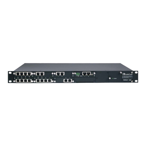
AudioCodes
AudioCodes Mediant 1000 User manual
AudioCodes
AudioCodes Mediant 1000 MSBG Manual
AudioCodes
AudioCodes Mediant 2000 User manual
AudioCodes
AudioCodes Mediant 800 Assembly instructions
AudioCodes
AudioCodes MediaPack 1288 User manual
AudioCodes
AudioCodes MEDIAPACK VERSION 6.2 How to use
AudioCodes
AudioCodes Mediant 3000 User manual
AudioCodes
AudioCodes Mediant 600 User manual
AudioCodes
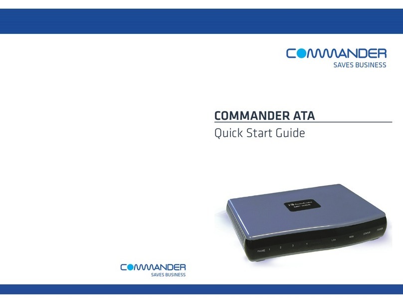
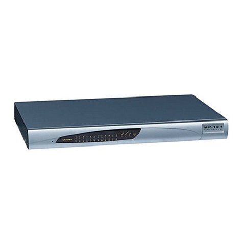
AudioCodes MediaPack MP-124 User manual
AudioCodes
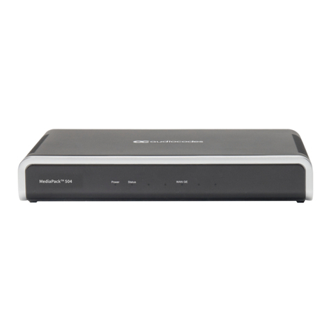
AudioCodes MediaPack 504 Assembly instructions
AudioCodes
AudioCodes Mediant 3000 User manual

AudioCodes
AudioCodes Mediant 2000 User manual
AudioCodes
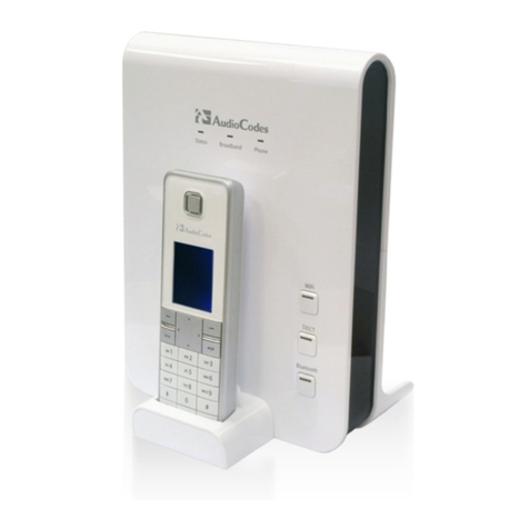
AudioCodes MP-26 series User manual

AudioCodes
AudioCodes Mediant 2000 User manual
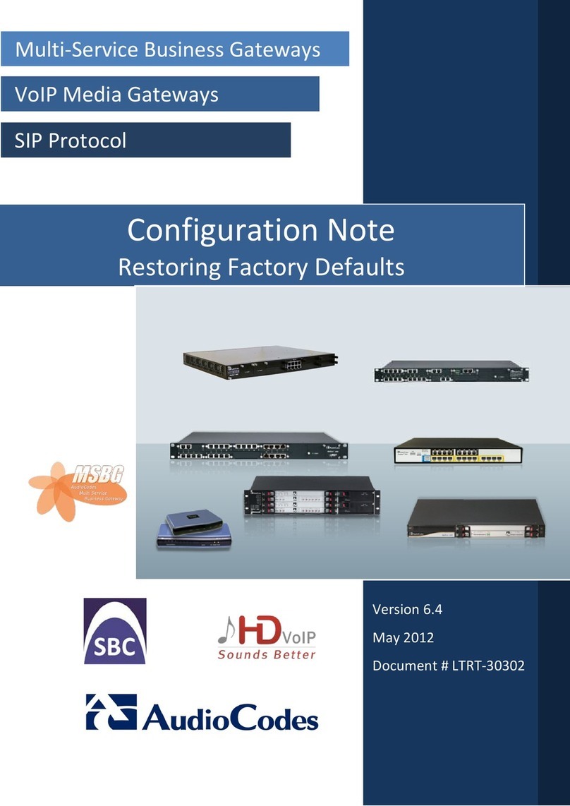
AudioCodes
AudioCodes MSBG Series Quick start guide

AudioCodes
AudioCodes Mediant 1000 User manual
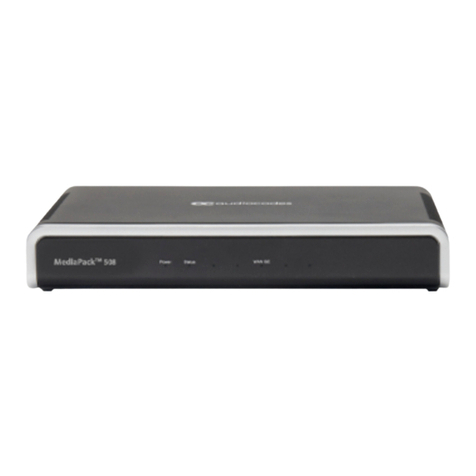
AudioCodes
AudioCodes MP-5 Series User manual

AudioCodes
AudioCodes Mediant 2000 User manual
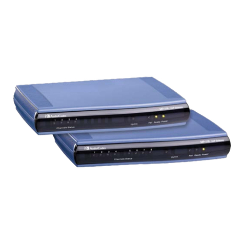
AudioCodes
AudioCodes MediaPack MP-112 Assembly instructions

AudioCodes
AudioCodes Mediant 600 User manual
Popular Gateway manuals by other brands
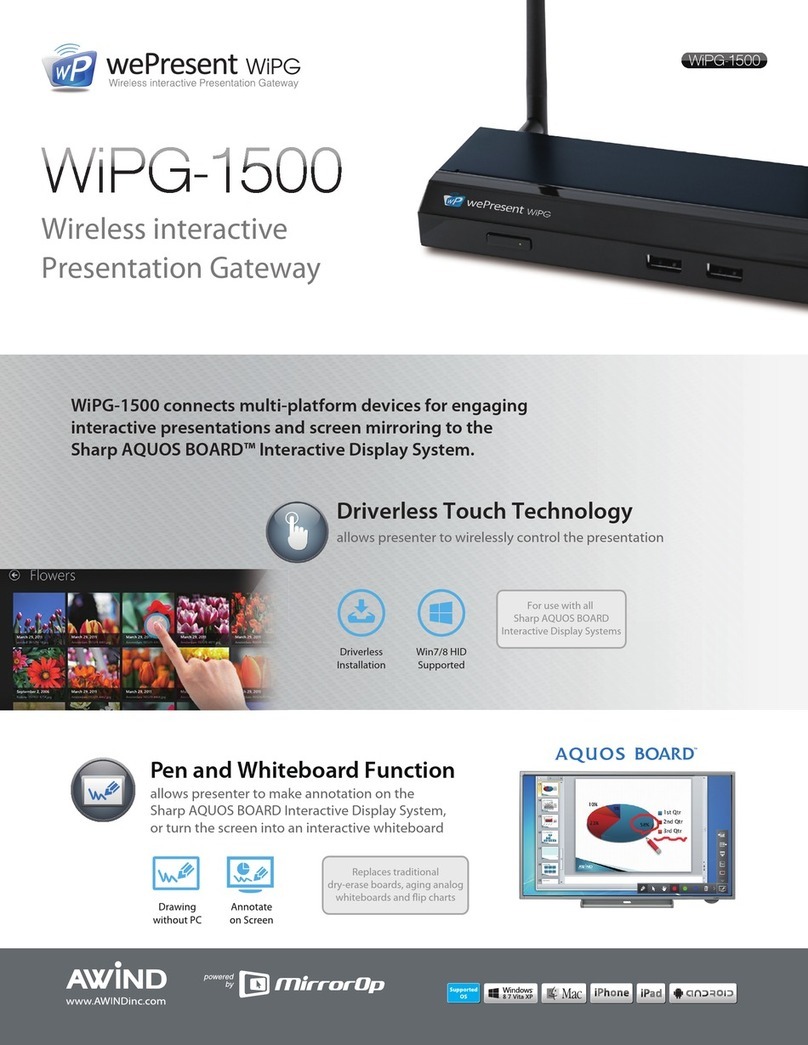
WePresent
WePresent WiPG-1500 Features & specifications
Telit Wireless Solutions
Telit Wireless Solutions GG863-SR Hardware user's guide
Trilliant
Trilliant SecureMesh GATE-1000 installation guide
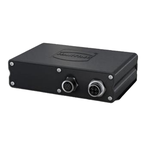
HARTING
HARTING OPC-UA user manual

Innoband
Innoband 8860-C1 user manual
Grandstream Networks
Grandstream Networks GXW-4104 Technical specifications
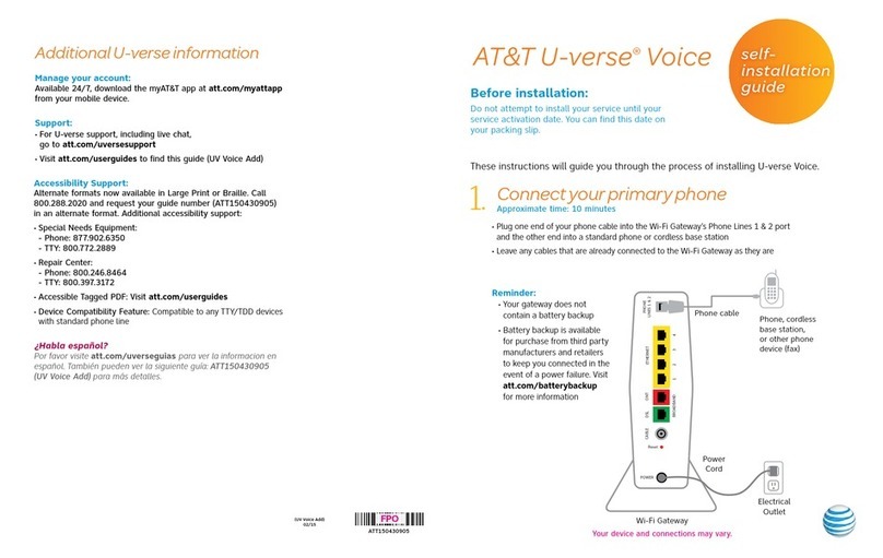
AT&T
AT&T U-verse TV Self-installation guide
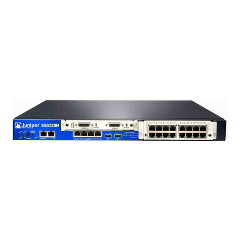
Juniper
Juniper SSG320M datasheet
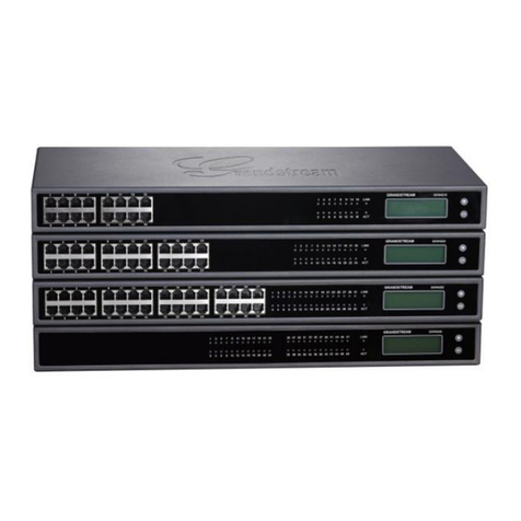
Grandstream Networks
Grandstream Networks GXW42XX series user manual
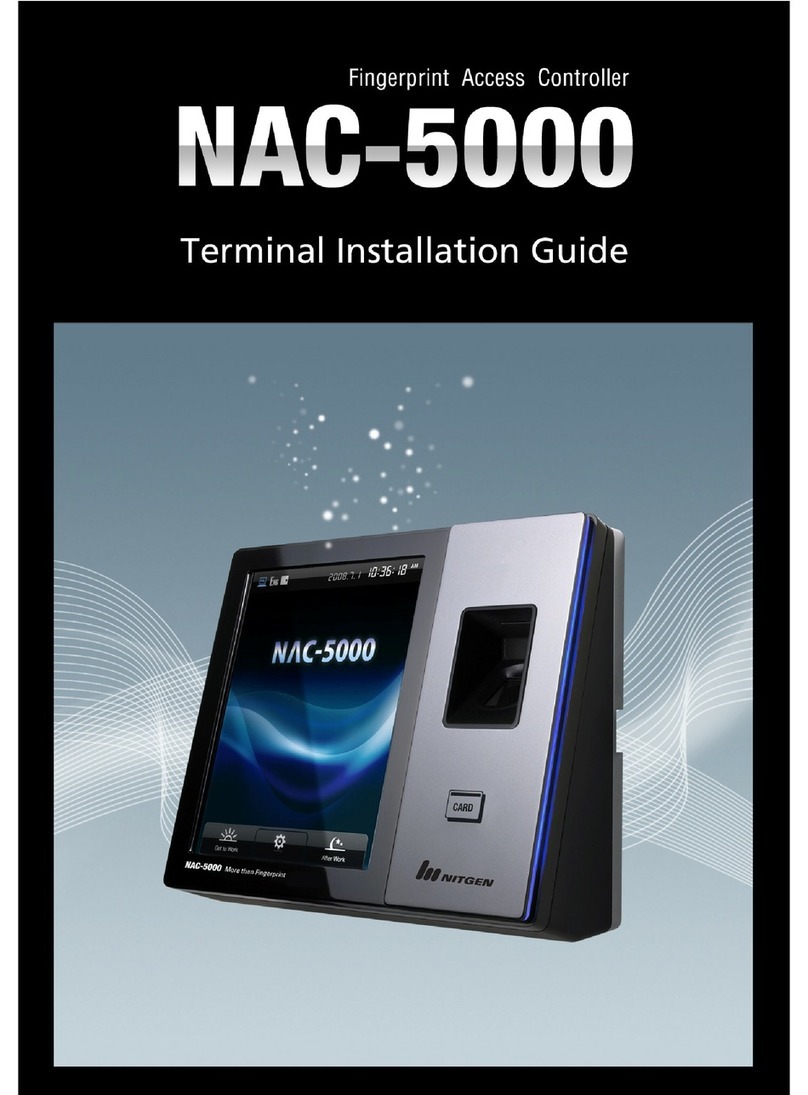
Nitgen
Nitgen NAC-5000 installation guide
Johnson Controls
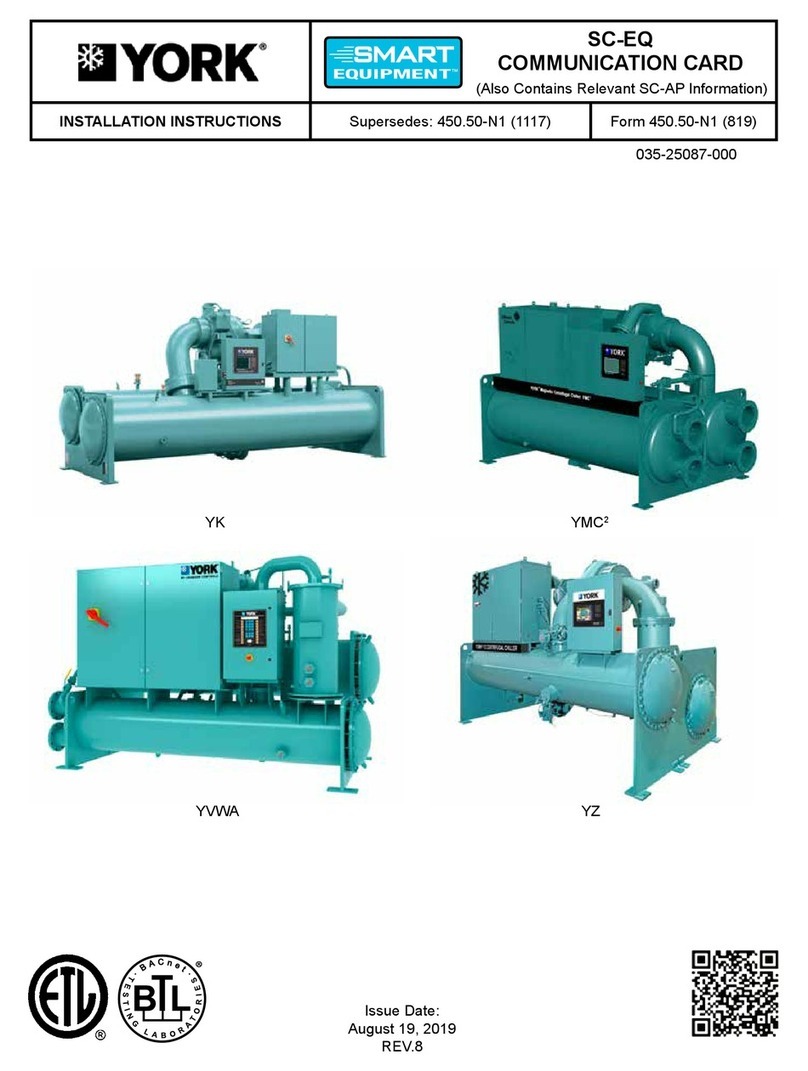
Johnson Controls York Smart Equipment SC-EQUIP installation instructions

ZyXEL Communications
ZyXEL Communications p-661hw series Specifications


