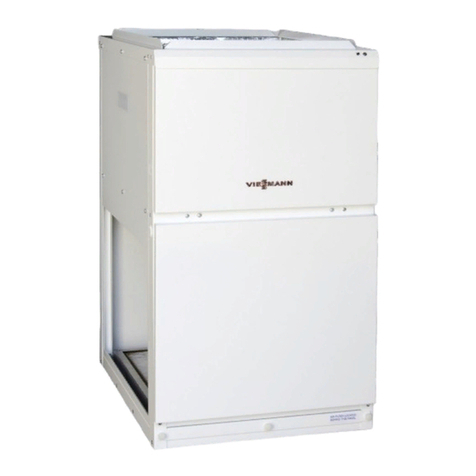
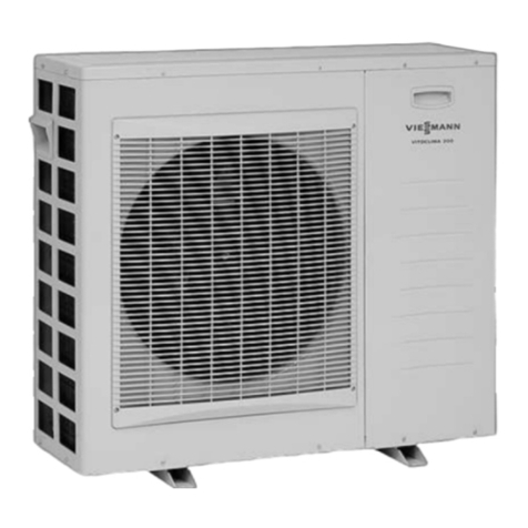
Viessmann VITOCAL 350-A Quick guide

Installation and service
instructions
for contractors
VIESMANN
Vitocal 350-A
Type AWH-I, AWH-O
Air/water heat pump with electric drive, 400 V~
For applicability, see the last page
VITOCAL 350-A
5414 828 GB 9/2009 Please keep safe.

2
Please follow these safety instructions closely to prevent accidents and mate-
rial losses.
Safety instructions explained
Danger
This symbol warns against the
risk of injury.
!Please note
This symbol warns against the
risk of material losses and envi-
ronmental pollution.
Note
Details identified by the word "Note" con-
tain additional information.
Target group
These instructions are exclusively
designed for qualified personnel.
■ Work on electrical equipment must
only be carried out by a qualified elec-
trician.
■ The system must be commissioned by
the system installer or a qualified per-
son authorised by the installer.
Regulations
Observe the following when working on
this system
■ all legal instructions regarding the pre-
vention of accidents,
■ all legal instructions regarding envi-
ronmental protection,
■ the Code of Practice of relevant trade
associations.
■ all current safety regulations as
defined by DIN, EN, DVGW, VDE and
all locally applicable standards
Working on the system
■ Isolate the system from the power sup-
ply and check that it is no longer 'live',
e.g. by removing a separate fuse or by
means of a main isolator.
■ Safeguard the system against unau-
thorised reconnection.
!Please note
Electronic modules can be dam-
aged by electrostatic dis-
charges.
Touch earthed objects, such as
heating or water pipes, to dis-
charge static loads.
Repair work
!Please note
Repairing components that fulfil a
safety function can compromise
the safe operation of your heating
system.
Replace faulty components only
with original Viessmann spare
parts.
Safety instructions
Safety instructions
5414 828 GB

3
Ancillary components, spare and
wearing parts
!Please note
Spare and wearing parts that
have not been tested together
with the heating system can com-
promise its function. Installing
non-authorised components and
non-approved modifications or
conversions can compromise
safety and may invalidate our
warranty.
For replacements, use only orig-
inal spare parts supplied or
approved by Viessmann.
Safety instructions
Safety instructions (cont.)
5414 828 GB

4
Installation instructions
Preparing for installation
Product information.............................................................................................. 8
General information - electrical connection.......................................................... 8
Internal heat pump, type AWH-I........................................................................... 8
External heat pump type AWH-O......................................................................... 17
Overview of possible system schemes................................................................ 30
Function description for the system examples..................................................... 30
System example 1................................................................................................ 34
System example 2................................................................................................ 39
DHW heating........................................................................................................ 47
Installation sequence
Removing the transport brackets......................................................................... 52
Fitting the outer panels......................................................................................... 52
Fitting the silencer hoods (only type AWH-O)...................................................... 60
Installing the heat pump....................................................................................... 61
Connecting the heating circuits and condensate drain........................................ 64
Electrical connections in the control panel........................................................... 68
Electrical connections in the heat pump control unit............................................ 75
Power supply........................................................................................................ 104
Closing the heat pump......................................................................................... 114
Service instructions
Commissioning, inspection, maintenance
Steps - commissioning, inspection and maintenance.......................................... 116
Further details regarding the individual steps....................................................... 117
Troubleshooting
Control unit diagnostics........................................................................................ 131
Measures in case the room temperature is constantly too low............................ 163
No programming unit display................................................................................ 164
Repairs................................................................................................................. 165
Control settings
Menu structure overview...................................................................................... 168
Control settings by the contractor......................................................................... 168
System definition control settings
System scheme.................................................................................................... 169
Language............................................................................................................. 169
Temperature differential for the heating limit........................................................ 169
Index
Index
5414 828 GB

5
Swimming pool..................................................................................................... 170
Cascade............................................................................................................... 170
Number of lag heat pumps................................................................................... 171
Output of lag heat pumps..................................................................................... 172
External extension................................................................................................ 172
External operating mode changeover heating circuits......................................... 173
Operating mode for external operating mode changeover................................... 174
External operating mode changeover duration.................................................... 174
External demand/mixer "OPEN"........................................................................... 175
External blocking/mixer "CLOSED"...................................................................... 176
Pumps and compressor, external blocking.......................................................... 177
Vitosolic................................................................................................................ 178
Vitocom 100......................................................................................................... 178
Auxiliary output with switching times.................................................................... 179
Compressor control settings
Enabling the compressor...................................................................................... 180
Heat pump output................................................................................................. 180
Defrost stop temperature...................................................................................... 181
Control settings, external heat source
Enable external heat source................................................................................. 182
Priority of external heat sources........................................................................... 182
Dual-mode temperature....................................................................................... 182
External heat source for DHW.............................................................................. 183
DHW control settings
Set cylinder temperature...................................................................................... 184
DHW switching times........................................................................................... 184
Minimum temperature for DHW cylinder.............................................................. 184
Maximum temperature for DHW cylinder............................................................. 184
Hysteresis/Hysteresis booster heater................................................................... 185
DHW start optimisation......................................................................................... 186
DHW stop optimisation......................................................................................... 186
DHW auxiliary function......................................................................................... 186
Set DHW temperature 2....................................................................................... 186
Temperature sensor 2.......................................................................................... 186
Parameters for DHW reheating............................................................................ 187
Control settings, electric heater
Instantaneous heating water heater (accessory)................................................. 189
Maximum stage, electric booster heater.............................................................. 189
Stage at power-OFF............................................................................................. 190
Index
Index
5414 828 GB

6
Control settings, hydraulics
Heat pump for drying buildings............................................................................. 191
Screed programme............................................................................................... 191
Set flow temperature in case of external demand................................................ 193
Operation with three-way diverter valve............................................................... 194
Control settings, heating water buffer cylinder
Heating water buffer cylinder................................................................................ 195
Switching times, heating water buffer cylinder..................................................... 195
Set temperature for fixed value (switching times)................................................ 195
Hysteresis............................................................................................................. 195
Maximum temperature......................................................................................... 196
Control settings, heating circuits
Room temperatures and switching times............................................................. 197
Enabling the remote control................................................................................. 197
Heating curve slope/level..................................................................................... 197
Influence of room temperature hook-up............................................................... 197
Room temperature hook-up (heating circuits)...................................................... 198
Maximum set flow temperature............................................................................ 198
Control settings - communication
LON communication module................................................................................ 200
LON system number / LON subscriber number................................................... 200
Fault manager...................................................................................................... 201
Time via LON....................................................................................................... 201
Outside temperature via LON............................................................................... 202
Data receive interval............................................................................................. 202
Heat pump numbers in a cascade........................................................................ 203
Date/time control settings
Date and time....................................................................................................... 204
Automatic summer/wintertime changeover.......................................................... 204
Connection and wiring diagrams
Overview of the PCBs and connection options.................................................... 205
Safety chain, control circuit, main power circuit................................................... 213
Parts lists
Parts list, type AWH-I........................................................................................... 224
Parts list, type AWH-O......................................................................................... 232
Index
Index
5414 828 GB

7
Commissioning/service reports
Hydraulic parameters report................................................................................. 241
Control parameters report.................................................................................... 241
Specification....................................................................................................... 245
Appendix
Heat pump commissioning order.......................................................................... 249
Certificates
Declaration of conformity...................................................................................... 250
Keyword index.................................................................................................... 251
Index
Index (cont.)
5414 828 GB

8
Vitocal 350-A, type AWH-I, AWH-O
Air/water heat pump without integral circulation pump (secondary pump) and without
three-way diverter valve. A secondary pump assembly (secondary pump and circu-
lation pump for cylinder heating) is available as an accessory.
The four red cores in the heat pump control unit must be removed for the external
circulation pumps to be connected (see page 82).
General information - electrical connection
■ The total output of all components con-
nected directly to the heat pump con-
trol unit (e.g. pumps, valves, message
facilities, contactors) must not exceed
1000 W.
If the total output ≤ 1000 W, the indi-
vidual rating of a component (e.g.
pump, valve, message facility, contac-
tor) can be greater than specified (see
page 245).
■ If two components are connected to
the same terminal, press both cores
together into a single wire ferrule.
■ If the compressor and/or instantane-
ous heating water heater (accessory)
are operated at a lower tariff (power-
OFF), provide an additional cable for
the power-OFF signal (e.g. NYM 3 x
1.5 mm2) from the distribution board
(meter box) to the heat pump control
unit (see page 105).
■ The number of power cables from the
distribution board (meter box) to the
heat pump control unit and to the con-
trol panel depends on the system ver-
sion and tariffs used (see from
page 104).
■ The cores of the KM BUS cable are
interchangeable.
For further information, see control panel
(page 70), heat pump control unit
(page 75) and power supply
(page 104).
Internal heat pump, type AWH-I
!Please note
Avoid damaging the appliance
during handling.
Never put weight on the top, front
or side panels of the appliance.
!Please note
Installing a compressor at a steep
angle inside the heat pump can
result in equipment damage.
Preparing for installation
Product information
5414 828 GB

9
Never tilt the heat pump more
than 45° during handling and
installation.
Requirements of the installation room
!Please note
Incorrect ambient conditions can
lead to system damage and can
put the safe operation at risk.
■ The installation room must be
dry and free from the risk of
frost.
Ensure ambient temperatures
above 0 ºC and below 35 ºC.
■ Prevent air contamination by
halogenated hydrocarbons
(e.g. as contained in paints,
solvents or cleaning fluids) and
excessive dust (e.g. through
grinding/polishing work).
■ Avoid continuously high humid-
ity levels (e.g. through frequent
drying of washing).
!Please note
Overloading the floor can result in
building damage.
Observe the permissible floor
load.
■ Total weight:
AWH-I 110 287 kg
AWH-I 114 297 kg
AWH-I 120 361 kg
■ To prevent structure-borne noise,
never set up the appliance on ceilings
with wooden joists (e.g. in the attic).
■ Observe minimum clearances.
■ Level the appliance.
■ Required room height at least 2.10 m.
■ Observe min. room volume required:
AWH-I 110 13.55 m3
AWH-I 114 16.13 m3
AWH-I 120 17.10 m3
Preparing for installation
Internal heat pump, type AWH-I (cont.)
5414 828 GB
Installation

10
Installation
Min. clearances and dimensions for installation against the wall
g
≥ 2800 (8 x 350)
≤ 4200 (12 x 350)
885
885
≥ 3000
830
990
686
80
350
810
h
965
Discharge side on the left (delivered condition); hydraulic connections on the right
(on site)
AWall outlet/duct part made of EPP
(expanded polypropylene)
BWeather grilles
CConnection on the inlet side made of
EPP (air inlet)
DHeat pump
EConnection on the discharge side
made of EPP (air discharge)
F90° bend made of EPP
Preparing for installation
Internal heat pump, type AWH-I (cont.)
5414 828 GB

11
Dimensions
Type AWH-I g h
110 880 845
114 1020 995
120 1180 1148
Minimum clearances and shell dimensions for installation in a corner
1330
532
1330
935
d
830
990
g
OKFFB
Discharge side on the left (delivered condition); hydraulic connections on the right
(on site)
AWall outlet OKFFB Top edge, finished floor
Preparing for installation
Internal heat pump, type AWH-I (cont.)
5414 828 GB
Installation

12
Shell dimensions
Type AWH-I d g
110 523 880
114 588 1020
120 686 1180
Information regarding shell dimen-
sion"d"
In unfinished buildings, please note that
the thickness of the final coating/render
must be added to the wall clearance
"d".
Preparing for installation
Internal heat pump, type AWH-I (cont.)
5414 828 GB

13
d
e
80
117
80
668
532
127
h
810
b
f
≥ 700
Discharge side on the left (delivered condition); hydraulic connections on the right
(on site)
AExternal rendering
BWall
Preparing for installation
Internal heat pump, type AWH-I (cont.)
5414 828 GB
Installation

14
CDuct part made of EPP (can be trim-
med to the required size from the
outside. Observe thickness of ren-
der)
DCompression sealing strip and
acrylic airtight seam (all-round)
EPU foam (all-round)
FPlaster finish/wall coating
Dimensions
Type AWH-I b d e f h
110 367 523 118 95 845
114 217 588 183 85 995
120 64 686 284 107 1148
Information regarding shell dimen-
sion"d"
In unfinished buildings, please note that
the thickness of the final coating/render
must be added to the wall clearance
"d".
Preparing for installation
Internal heat pump, type AWH-I (cont.)
5414 828 GB

15
Connections
b
95
c
a
946
1870
639
946
111
218
327
435
Note
Hydraulic pipes, cables and condensate drain can be routed out of the heat pump to
the left or right.
ACable entries
BHeating water return/DHW cylinder
return (see page 64)
CCondensate drain
DHeating water flow/DHW cylinder
flow (see page 64)
Preparing for installation
Internal heat pump, type AWH-I (cont.)
5414 828 GB
Installation

16
Dimensions
Type AWH-I a b c
110 489 367 880
114 489 217 1030
120 472 64 1200
Cables (for installation see from page 68)
A
C
D
G
E
H
F
K
B
AHeat pump control unit
Wall outlet for cables: central,
directly below the heat pump control
unit
BPower cable for heat pump control
unit 230 V/50 Hz
Recommended cable: 3 x 1.5 mm2
CPower cables for further compo-
nents and functions:
■ Pumps/pump control
■ Mixer
■ Sensors
■ Auxiliary functions (power-OFF,
external blocking, external
demand, external heat source
control, etc.)
■ Fault message
■ Two-way shut-off valve
■ Communication facilities
■ KM BUS
■ Remote control
DTwo connecting cables, fully wired
(5, 15 or 30 m):
■Control cable 230 V~
■Low voltage cable < 42 V
Preparing for installation
Internal heat pump, type AWH-I (cont.)
5414 828 GB

17
EPower cable for compressor/fan
(400 V/50 Hz; 3/N/PE)
Recommended cable: 5 x 2.5 mm2
FPower cable for instantaneous heat-
ing water heater
(400 V/50 Hz; 3/N/PE; max. output
9 kW)
Recommended cable: 5 x 2.5 mm2
GInstantaneous heating water heater
(accessory)
HControl panel
KHeat pump type AWH-I
Required cable lengths:
■ For the heat pump control unit from the
wall outlet:
0.7 m
■ Inside the heat pump (to the control
panel):
3.4 m plus wall clearance for cable
entry from the left
3.4 m plus wall clearance minus appli-
ance width for cable entry from the
right
External heat pump type AWH-O
!Please note
Avoid damaging the appliance
during handling.
Never put weight on the top, front
or side panels of the appliance.
!Please note
Installing a compressor at a steep
angle inside the heat pump can
result in equipment damage.
Never tilt the heat pump more
than 45° during handling and
installation.
Preparing for installation
Internal heat pump, type AWH-I (cont.)
5414 828 GB
Installation

18
Requirements
■ Provide a manual draining facility for
the heating flow and return lines in the
area at risk from frost (see page 26).
If the heat pump control unit and heat-
ing circuit pump are ready for opera-
tion, the frost protection function of the
heat pump control unit is enabled.
Drain the system if the heat pump is
shut down or there is a prolonged
power failure.
In heat pump systems where a power
failure would not be detected (holiday
home), operate the heating circuit with
suitable antifreeze or drain the circuit
(see page 29).
■ To prevent air "short circuits" and
higher sound emissions through
reflection, avoid installing the equip-
ment in recesses, on building corners
or between two walls. Lawn areas and
vegetation can reduce noise develop-
ment.
Only the heat pump foundations
should therefore be made from rever-
berative material (concrete).
■ Never install the heat pump next to liv-
ing rooms or bedrooms.
■ The air in the outlet section is approx.
10 K colder than the ambient air.
Therefore, black ice could develop in
the outlet area even at [ambient] tem-
peratures above freezing. Clearance
to pavements or terraces: ≥ 3 m.
Preparing for installation
External heat pump type AWH-O (cont.)
5414 828 GB

19
Installation
Minimum clearances
1500
800
1200
1500
Foundations
Position the heat pump horizontally on a
permanently solid surface. We recom-
mend laying concrete foundations as
shown in the following diagrams.
■ Provide an adequately sized recess
(see diagram below) in the founda-
tions to permit the lines (heating water
flow and return, cables and conden-
sate drain) to be brought into the heat
pump from below.
■ The foundations, supporting surface
and cable ducts must be designed to
prevent rodents from entering the heat
pump and the cable ducts.
■ Drain all condensate derived from the
air (subject to temperature and relative
humidity up to 20 l/h) via a DN 40 drain
pipe, which should be protected from
frost and provide a steady fall.
If possible connect the condensate
drain to a drainage or sewer system.
In this case, provide a siphon with a
water level of at least 60 mm in the
frost-protected area.
Preparing for installation
External heat pump type AWH-O (cont.)
5414 828 GB
Installation

20
Where the ground is able to absorb
water, the condensate can be soaked
away down to a frost-free depth into a
gravel bed.
Technical guide
Weight (with silencer hoods)
AWH-O 110 325 kg
AWH-O 114 335 kg
AWH-O 120 400 kg
Preparing for installation
External heat pump type AWH-O (cont.)
5414 828 GB
Other manuals for VITOCAL 350-A
3
Table of contents
Other Viessmann Air Conditioner manuals
Popular Air Conditioner manuals by other brands

Bryant
Bryant Evolution Extreme 186CNV installation instructions

Dometic
Dometic FreshWell3000 installation manual

Airxcel
Airxcel Marvair ComPac II AVHDA90 Installation & operation manual

Mitsubishi Electric
Mitsubishi Electric MSC-GE20VB operating instructions

Mitsubishi Electric
Mitsubishi Electric NTXFKs15a112a Series manual

Technibel
Technibel KPAFP125R5IA Series instruction manual