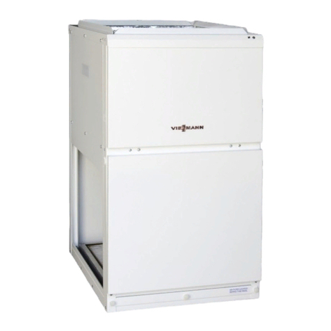
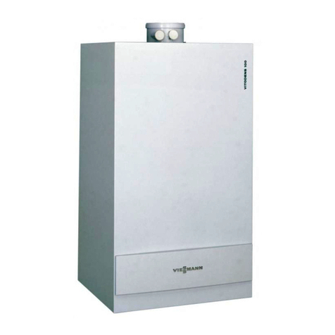
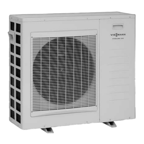
Viessmann Vitoclima 300-S Operating instructions

VIESMANN
Service instructions
for contractors
Vitoclima 300-S
Single split air-conditioning unit with inverter technology
Comprising an external unit and an internal device
For applicability, see the last page
VITOCLIMA 300-S
5692 687 GB 8/2008 Please keep safe.

Please follow these safety instructions closely to prevent accidents and
material losses.
Safety instructions explained
Danger
This symbol warns against the
risk of injury.
!Please note
This symbol warns against the
risk of material losses and
environmental pollution.
Note
Details identified by the word "Note"
contain additional information.
Target group
These instructions are exclusively
designed for qualified personnel.
&Work on the refrigeration circuit
must only be carried out by qualified
and authorised refrigeration engi-
neers.
&Work on electrical equipment must
only be carried out by a qualified
electrician.
&The system must be commissioned
by the system installer or a qualified
person authorised by the installer.
Regulations
Observe the following when working
on this system
&all legal instructions regarding the
prevention of accidents,
&all legal instructions regarding
environmental protection,
&the Code of Practice of relevant
trade associations.
&all current safety regulations as
defined by DIN, EN, VDE and all
locally applicable standards
Working on the system
&Isolate the system from the power
supply and check that it is no longer
'live', e.g. by removing a separate
fuse or by means of a main isolator.
&Danger
Contact with 'live' compo-
nents can lead to severe inju-
ries. Some components on
the PCBs will remain 'live'
even after the power supply
has been switched OFF.
&Prior to removing equipment
covers wait at least 4 min. to
allow the voltage to dissi-
pate.
&Safeguard the system against
unauthorised reconnection.
!Please note
Electronic modules can be
damaged by electrostatic dis-
charges.
Touch earthed objects, such as
heating or water pipes, to dis-
charge static loads.
Safety instructions
2
Safety instructions
5692 687 GB

Repair work
!Please note
Repairing components that ful-
fil a safety function can com-
promise the safe operation of
your system.
Replace faulty components
only with original Viessmann
spare parts.
Ancillary components, spare and
wearing parts
!Please note
Spare and wearing parts that
have not been tested together
with the heating system can
compromise its function. Instal-
ling non-authorised compo-
nents and non-approved
modifications or conversions
can compromise safety and
may invalidate our warranty.
For replacements, use only ori-
ginal spare parts supplied or
approved by Viessmann.
Safety instructions (cont.)
3
Safety instructions
5692 687 GB

Commissioning, inspection, maintenance
Steps - commissioning, inspection and maintenance ................................... 5
Further details regarding the individual steps .............................................. 7
Troubleshooting
Diagnosis ................................................................................................... 15
Refrigerant circuit..................................................................................... 30
Connection and wiring diagrams
Internal devices .......................................................................................... 31
External units ............................................................................................. 38
Parts lists
Parts lists, internal devices ......................................................................... 42
Parts list, external units............................................................................... 43
Commissioning/service reports
Maintenance checklist Vitoclima 200-S/300-S ............................................. 44
Specification
Specification............................................................................................... 46
Specification, internal devices..................................................................... 49
Specification external units ......................................................................... 51
Certificates
Declaration of conformity ............................................................................ 52
Keyword index .......................................................................................... 53
Index
4
Index
5692 687 GB

For further information regarding the individual steps, see the page indicated
Commissioning steps
Inspection steps
Maintenance steps Page
!!!
••• 01. Switching OFF the unit and the main fuse/MCB ........ 7
•02. Evacuating the refrigerant lines and the internal
device ........................................................................................ 7
•03. Filling the refrigerant lines and internal device
with refrigerant ...................................................................... 8
••• 04. Checking the refrigerant lines for leaks ....................... 10
•05. Checking the oil lifting bends in the vacuum pipe . . . 10
•06. Checking the thermal insulation at the flanged
connections
• • 07. Checking the tightness of electrical connections
••• 08. Checking the condensate drain of the internal
device ........................................................................................ 11
••• 09. Checking the free rotation of the external fan............ 12
•10. Cleaning the heat exchanger of the external unit ..... 12
• • 11. Cleaning the air filter of the internal device ................ 13
• • 12. Replacing or cleaning the electrostatic filter of the
internal device (if installed)............................................... 13
• • 13. Replacing the active charcoal filter (if installed) ...... 13
••• 14. Switching ON the main fuse/MCB
••• 15. Switching the unit ON.......................................................... 14
••• 16. Checking the unit for unusual noises
••• 17. Checking the system function (output test) ............... 14
• • 18. Checking the display of the remote control
•19. Twice annual maintenance in accordance with the
checklist from page 44
•20. Instructing the system user
Steps - commissioning, inspection and maintenance
5
Commissioning, inspection, maintenance
5692 687 GB

Commissioning steps
Inspection steps
Maintenance steps Page
!!!
21. Charging the external unit with refrigerant (if units/
devices must be separated) .............................................. 14
Steps - commissioning, inspection and . . . (cont.)
6
Commissioning, inspection, maintenance
5692 687 GB

Switching OFF the unit and the main fuse/MCB
Danger
Touching 'live' components can result in the transfer of dangerous body
currents.
Isolate the unit from the power supply, check that it is no longer 'live' and
safeguard against unauthorised reconnection.
Evacuating the refrigerant lines and the internal device
Note
Prior to evacuating the system, carry out a leak test (pressure test with dried
nitrogen).
AVacuum pump
Further details regarding the individual steps
7
Commissioning, inspection, maintenance
5692 687 GB

BFilling hose for connecting the
pressure gauge set and the
vacuum pump
CPressure gauge set
DFilling hose for the suction side
(one hose end with valve)
EExternal unit
FInternal device
GSuction line
HLiquid line
KService valve with protective cap
LThree-way valve
Evacuate the system at the service
valve of the external unit.
1. Connect the ends of the filling hose
without valves with the inlet con-
nection of pressure gauge set C.
2. Remove protective cap from ser-
vice valve Kof three-way diverter
valve Land connect filling hose
D.
3. Connect the centre hose Bof
pressure gauge set Cwith
vacuum pump A.
4. Start vacuum pump A.
Let the pump run for 15 min.
5. Close the valve between pressure
gauge set Cand vacuum pump.
Stop vacuum pump Aand wait 5
min.
Should the indicated value change
within this period, that would indi-
cate a leak.
Remove the leak and repeat the
process.
6. Run vacuum pump Auntil a
vacuum has been built (the value
indicated by the pressure gauge
must be near to 0 bar).
Note
The pump runtime will be subject to
the ambient conditions.
7. Remove filling hose Dfrom ser-
vice valve K, then first fit and sub-
sequently tighten the protective
cap with 11 to 13 Nm.
Filling the refrigerant lines and internal device with refriger-
ant
Note
The external unit is already pre-filled with refrigerant.
With longer lines it may be necessary to top up the system with refrigerant. See
"Specification" on page 51.
Further details regarding the individual steps (cont.)
8
Commissioning, inspection, maintenance
5692 687 GB

AValve (liquid line)
BValve shut-off (open/close with an
Allen key)
CProtective valve cap
DThree-way valve (suction line)
EValve shut-off (open/close with an
Allen key)
FProtective valve cap
GSuction line
HLiquid line
KExternal unit
1. Remove protective valve caps C
and Ffrom valves Aand Dof
external unit K.
2. Open valve locksBand Ewith
an Allen key.
3. Fit and tighten protective valve
caps Cand Fwith 11 to 13 Nm.
Further details regarding the individual steps (cont.)
9
Commissioning, inspection, maintenance
5692 687 GB

Checking the refrigerant lines for leaks
Danger
Prevent an unregulated escape
of R 410A in sealed rooms;
ensure adequate ventilation.
Always observe all relevant
regulations and directives
regarding the handling of
refrigerant.
Note
In this refrigerant circuit the refriger-
ant R 410A is used. R 410A is a non-
toxic gas that displaces air and is
composed of two constituents.
&R 32 (CH2F2): 60 % total proportion
&R 125 (CF3CHF2): 40 % total pro-
portion
The above specifications are subject
to modification without prior notice.
Check all flanged connections of the
refrigerant lines between the internal
device and the external unit for refrig-
erant leaks.
Check all soldered points and connec-
tions of the refrigerant lines in the
internal device and the external unit
for refrigerant leaks.
Further work on the refrigeration cir-
cuit must only be carried out by a qua-
lified refrigeration engineer.
Checking the oil lifting bends in the vacuum pipe
Not applicable to type OS307H.
Install oil lifting bends in the vertical line at the lowest point and at distances of 5
m.
Further details regarding the individual steps (cont.)
10
Commissioning, inspection, maintenance
5692 687 GB

AInternal device
BSuction line
CLiquid line
DExternal unit
EOil lift bends
Checking the condensate drain of the internal device
!Please note
Accumulations of condensate
can result in equipment
damage.
Ensure that the condensate
drains off correctly.
Fill the condensate pan of the internal
device with water.
Should the water not drain fully
through the drain hose of the internal
device:
&Check the horizontal level of the
internal device (the condensate pan
must have a slope).
&Check the drain of the condensate
pan for blockages.
&Check the drain line. The slope
must be at least 2 % along the entire
drain line.
Further details regarding the individual steps (cont.)
11
Commissioning, inspection, maintenance
5692 687 GB

Checking the free rotation of the external fan
Danger
Unintentional starting of the fan
can lead to severe injuries.
Isolate the unit from the power
supply, check that it is no
longer 'live' and safeguard
against unauthorised recon-
nection.
1. Remove the front grille from the
external unit.
2. Turn the fan by hand.
Cleaning the heat exchanger of the external unit
1. Open the casing of the external
unit.
!Please note
The sharp edges of the heat
exchanger can result in inju-
ries.
Avoid contact with the
exchanger.
2. !Please note
Excessive air pressure can
result in the deformation of
the aluminium fins of the
heat exchanger.
Only point the compressed
air gun at the heat exchan-
ger from the front and at an
adequate distance. Air
forced at the aluminium fins
from the side will result in
their deformation.
Blow out the heat exchanger from
the inside out with compressed air.
3. Check the aluminium fins of the
heat exchanger for deformation
and scratches; if required repair
with a suitable tool.
4. Close the casing of the external
unit.
Further details regarding the individual steps (cont.)
12
Commissioning, inspection, maintenance
5692 687 GB

Cleaning the air filter of the internal device
Note
The air filter prevents the ingress of dust and other particles.
A blocked air filter can reduce the output of the air-conditioning unit substan-
tially.
Check the condition of the air filter regularly.
Wall mounted devices are fitted with a
filter cleaning indicator that lights up
after 500 hours of operation.
Check the operating instruc-
tions for information regarding
the removal and installation of
the air filter.
Clean the air filter with a vacuum clea-
ner or fresh water.
In case of severe contamination, use
a soft brush and mild detergent.
Let the air filter dry in a cool place.
Replacing or cleaning the electrostatic filter of the internal
device (if installed)
Replace or clean the electrostatic filter every three months in use.
Note
Replace contaminated electrostatic single use filters.
A reusable filter is available as an option. This filter can be cleaned.
Check the operating instruc-
tions for information regarding
the removal and installation of
the filter.
Clean the reusable filter in a warm
soapy solution and let it dry thor-
oughly.
Replacing the active charcoal filter (if installed)
Replace the active charcoal filter annually (it cannot be cleaned).
Further details regarding the individual steps (cont.)
13
Commissioning, inspection, maintenance
5692 687 GB

Switching the unit ON
Switch on the unit with the remote
control of the internal device.
See operating instructions.
Checking the system function (output test)
Allow the unit to operate in cooling
mode for at least 15 min at a high fan
speed.
Check the temperature of the inrush-
ing and blown-out air.
The temperature differential should be
at least 8 K.
Charging the external unit with refrigerant (if units/devices
must be separated)
If the external unit and the internal device must be separated, the external unit
can be charged with refrigerant.
1. Set the system to cooling.
2. Close the liquid valve (see Fig. on
page 9).
3. Close the suction gas valve (see
Fig. on page 9), when the pressure
gauge of the gauge set (see Fig. on
page 8) indicates 0 bar.
4. Undo the refrigerant lines.
Further details regarding the individual steps (cont.)
14
Commissioning, inspection, maintenance
5692 687 GB

Scanning fault codes in diagnostic mode
In diagnostic mode, fault codes can be scanned individually for the internal
device and the external unit.
For a detailed description of the control and display elements, see the
operating instructions for the "Vitoclima-S".
Enabling the diagnostic mode:
Hold down the "MODE" key at the
internal device (for duct mounted
devices at the receiver) for 5 to 10 s.
The diagnostic mode is acknowl-
edged by three short tones and the
illumination of the cooling and heating
LEDs.
Switching between the diagnosis of
the external unit and the diagnosis
of the internal device:
Every additional brief pressing of the
"MODE" key enables a changeover
between the internal device and the
external unit. This is acknowledged by
three short tones and the illumination
of the cooling and heating LEDs.
The remaining LEDs on the internal
device flash whilst the diagnosis of
the external unit progresses.
The remaining LEDs on the internal
device flash whilst the diagnosis of
the internal device progresses.
Fault codes of the internal device
Fault codes are illustrated through the simultaneous illumination of the cooling
and heating LEDs.
The heating LED illuminates 5 times in succession. Either the cooling LED illu-
minates at the same time or not.
This results in the fault code detailed in the following table:
Note
Only one fault code will be displayed, even if several faults have occurred.
To display further fault codes:
&Switch the unit OFF and isolate it from the power supply.
&Remove the fault.
&Call up the diagnostic function again.
Diagnosis
15
Troubleshooting
5692 687 GB

No. Fault code Fault Cause/Remedy
54321
1∘ ∘ ∘ ∘ ●Room temperature
sensor not connected
Check sensor connection;
replace sensor
2∘ ∘ ∘ ●∘Room temperature
sensor short circuit
3∘ ∘ ∘ ● ● Temperature sensor of
the heat exchanger of
the internal device not
connected
4∘ ∘ ●∘ ∘ Short circuit of the
temperature sensor of
the heat exchanger of
the internal device
5∘ ∘ ●∘●Suction gas tempera-
ture sensor not con-
nected
6∘ ∘ ● ● ∘(N/A)
7∘ ∘ ●●●Communication error Incompatible controllers of
the internal device and the
external unit: Replace the
controller of the internal de-
vice
8∘●∘∘∘No communication Check the connecting cable
between the internal device,
the external unit and earth
9∘●∘ ∘ ●No code Check fan motor connection;
replace fan motor;
Replace the controller of the
internal device
10 ∘●∘●∘(N/A)
11 ∘●∘● ● External unit fault Change over to diagnosis of
external unit
... (N/A)
17 ●∘ ∘ ∘ ●Protection against
icing-up
18 ●∘ ∘ ●∘Defrost protection
19 ●∘ ∘ ● ● External unit protec-
tion
Diagnosis (cont.)
16
Troubleshooting
5692 687 GB

No. Fault code Fault Cause/Remedy
54321
20 ●∘●∘ ∘ Overtemperature cut-
out of the heat exchan-
ger of the internal de-
vice
... (N/A)
24 ● ● ∘∘∘EEPROM not updated Unit operates with ROM
parameters; no change of
the unit settings (fan, tem-
perature etc.) possible.
Replace the controller of the
internal device.
25 ● ● ∘ ∘ ●EEPROM faulty
26 ● ● ∘●∘Poor communication Check the electrical con-
necting cable between the
internal device, the external
unit and earth
27 ● ● ∘● ● Utilisation of EEPROM
data
No fault
28 ● ● ● ∘ ∘ Model A
29 ● ● ● ∘●Model B
30 ● ● ● ● ∘Model C
31 ● ● ● ● ● Model D
●Cooling and heating LEDs illumi-
nate together
∘Only the heating LED illuminates
Fault codes, external unit, type OS303H, OS304H and OS305H
Fault codes are illustrated through the simultaneous illumination of the cooling
and heating LEDs.
The heating LED illuminates 5 times in succession. Either the cooling LED illu-
minates at the same time or not.
This results in the fault code detailed in the following table:
Note
The fault code can also be checked at the LEDs of the external unit. Fault codes
are illustrated through the simultaneous illumination of the status and fault
LEDs. The status LED illuminates 5 times in succession. Either the fault LED
illuminates at the same time or not.
Diagnosis (cont.)
17
Troubleshooting
5692 687 GB

Note
Only one fault code will be displayed, even if several faults have occurred.
To display further fault codes:
&Switch the unit OFF and isolate it from the power supply.
&Remove the fault.
&Call up the diagnostic function again.
No. Fault code Fault Cause/Remedy
54321
1∘ ∘ ∘ ∘ ●Temperature sensor of
the heat exchanger of
the external unit not
connected
Check sensor connection;
replace sensor
2∘ ∘ ∘ ●∘Short circuit of the
temperature sensor of
the heat exchanger of
the external unit
3∘ ∘ ∘ ● ● Compressor tempera-
ture sensor not con-
nected
Check sensor connection;
replace sensor
4∘ ∘ ●∘ ∘ Compressor tempera-
ture sensor short cir-
cuit
5∘ ∘ ●∘●Processor temperature
sensor not connected
(if enabled)
Check sensor connection;
replace sensor
6∘ ∘ ● ● ∘Processor temperature
sensor short circuit (if
enabled)
7∘ ∘ ●●●Outside temperature
sensor not connected
(if enabled)
Check sensor connection;
replace sensor
8∘●∘∘∘Outside temperature
sensor short circuit (if
enabled)
9∘●∘ ∘ ●Suction gas tempera-
ture sensor not con-
nected (if enabled)
Check sensor connection;
replace sensor
10 ∘●∘●∘Suction gas tempera-
ture sensor short cir-
cuit (if enabled)
Diagnosis (cont.)
18
Troubleshooting
5692 687 GB

No. Fault code Fault Cause/Remedy
54321
11 ∘●∘● ● Processor fault Controller problem, external
unit: Check the connecting
cable and jumper settings;
replace controller
12 ∘● ● ∘ ∘ EEPROM faulty Device operates with ROM
parameters; replace the con-
troller of the external unit
13 ∘● ● ∘●DC undervoltage Check the voltage at the ex-
ternal unit
14 ∘● ● ● ∘DC overvoltage
15 ∘● ● ● ● AC undervoltage
16 ●∘ ∘ ∘ ∘ Communication error Incompatible controllers of
the internal device and the
external unit: Replace the
controller of the internal de-
vice
17 ●∘ ∘ ∘ ●No communication Check the electrical con-
necting cable between the
internal device, the external
unit and earth
... (N/A)
20 ●∘●∘ ∘ Processor overtem-
perature cut-out
21 ●∘●∘●Defrosting
22 ●∘● ● ∘Compressor over-
heated
23 ●∘●●●Compressor overcur-
rent
24 ● ● ∘∘∘No feedback, external
fan
25 ● ● ∘ ∘ ●External fan idle
26 ● ● ∘●∘Compressor idle Change over to standby and
restart
27 ● ● ∘● ● Poor communication Check the electrical con-
necting cable between the
internal device, the external
unit and earth
●Cooling and heating LEDs illumi-
nate together
∘Only the heating LED illuminates
Diagnosis (cont.)
19
Troubleshooting
5692 687 GB

Fault codes external unit, type OS307H
Fault codes are illustrated through the simultaneous illumination of the cooling
and heating LEDs.
The heating LED illuminates 5 times in succession. Either the cooling LED illu-
minates at the same time or not.
This results in the fault code detailed in the following table:
Note
The fault code can also be checked at the LEDs of the external unit. Fault codes
are illustrated through the simultaneous illumination of the status and fault
LEDs. The status LED illuminates 5 times in succession. Either the fault LED
illuminates at the same time or not.
Note
Only one fault code will be displayed, even if several faults have occurred.
To display further fault codes:
&Switch the unit OFF and isolate it from the power supply.
&Remove the fault.
&Call up the diagnostic function again.
No. Fault code Fault Cause/Remedy
54321
1∘ ∘ ∘ ∘ ●Temperature sensor of
the heat exchanger of
the external unit
Check sensor connection;
replace sensor
2∘ ∘ ∘ ●∘Compressor tempera-
ture sensor
3∘ ∘ ∘ ● ● Processor temperature
sensor
4∘ ∘ ●∘ ∘ Outside temperature
sensor
5∘ ∘ ●∘●Wet steam tempera-
ture sensor
6∘ ∘ ● ● ∘Suction gas tempera-
ture sensor
7∘ ∘ ●●●No feedback external
fan/compressor
Check the connections of the
external fan (voltage and ve-
locity sensor); check the fan
motor; check the compressor
connection and motor
Diagnosis (cont.)
20
Troubleshooting
5692 687 GB
Other manuals for Vitoclima 300-S
1
Table of contents
Other Viessmann Air Conditioner manuals
Popular Air Conditioner manuals by other brands

Honeywell
Honeywell CL30XC owner's manual

MegaLife
MegaLife NEBULA GREEN R32 Use and Installation Instructions

OMAS
OMAS Air-Fi AFT7 Installer and User Instruction Manual

Samsung
Samsung MH FSBA Series installation manual

dirna Bergstrom
dirna Bergstrom bycool green Series Troubleshooting

REMKO
REMKO SKT 521 Operating and installation instructions