Viewpoint 43832 User manual

WIRELESS DRIVEWAY ALERT
OWNER’S MANUAL
WARNING:
Read carefully and understand all ASSEMBLY AND OPERATION
INSTRUCTIONS before operating. Failure to follow the safety rules and other
basic safety precautions may result in serious personal injury.
Item# 43832

Page of 6
2
Thank you very much for choosing an ViewPoint product! For future reference, please complete
the owner’s record below:
Model: _______________ Purchase Date: _______________
Save the receipt, warranty and these instructions. It is important that you read the entire manual
to become familiar with this product before you begin using it.
This alert system is designed for certain applications only. The distributor cannot be responsible
for issues arising from modification. We strongly recommend this alert system not be modified
and/or used for any application other than that for which it was designed. If you have any
questions relative to a particular application, DO NOT use the alert system until you have first
contacted the distributor to determine if it can or should be performed on the product.
For technical questions please call 1-800-222-5381.
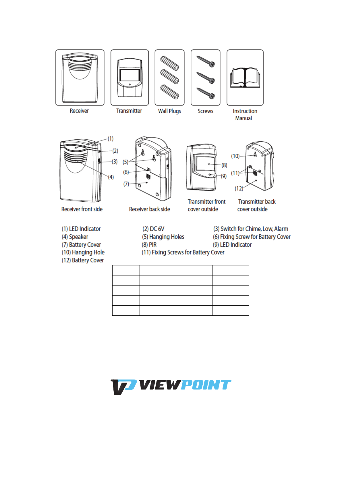
TECHNICAL SPECIFICATIONS
T
r
ansmitt
er
Power
R
equir
emen
ts
(3) AAA 1.5V
batteries (not
included)
PIR
Sensor
V
iewing
Area Approx.100 Degrees
H
or
iz
on
tal
PIR
Sensor
R
ange
24ft/8m approx. (varies by local
conditions)
T
r
ansmission
R
ange
368ft/120m approx. (varies by local
c
ondition)
Rec
eiv
er
Power
R
equir
emen
ts
3×C 1.5V
battery -not
included
Chime
V
olume
A
ppro
x. 90dB
GENERAL SAFETY RULES
WARNING: Read and understand all instructions. Failure to follow all instructions listed
below may result in serious injury.
CAUTION: Do not allow persons to operate or assemble this alert system until they
have read this manual and have developed a thorough understanding of how the alert
system works.
WARNING: The warnings, cautions, and instructions discussed in this instruction
manual cannot cover all possible conditions or situations that could occur. It must be
understood by the operator that common sense and caution are factors which cannot be built into
this product, but must be supplied by the operator.
SAVE THESE INSTRUCTIONS

Page of 6
3
IMPORTANT SAFETY CONSIDERATIONS
USE AND CARE
•Do not modify the alert system in any way. Unauthorized modification may impair the
function and/or safety and could affect the life of the equipment. There are specific applications
for which the alert system was designed.
•Always check of damaged or worn out parts before using the alert system. Broken parts
will affect the alert system operation. Replace or repair damaged or worn parts immediately.
•Store idle alert system. When alert system is not in use, store it in a secure place out of the
reach of children. Inspect it for good working condition prior to storage and before re-use.
NOTES BEFORE INSTALLATION
•
B
ef
or
e
installation and
op
er
a
tion,
you will require
a
dr
ill,
a
cross-headed
scr
ew
dr
iv
er
,
; (
3) AAA
1.5V
ba
tt
er
ies
,
; and
(3) C 1.5V
ba
tt
er
ies
.
All
of these are not supplied with this
k
it.
•
Do not mount the transmitter on a metal frame
.
•
Do not mount the r
ec
eiv
er
above heat sources such as
r
adia
t
ors
,
or in damp areas such as
a
kitchen
or
bathroom.
HOW IT WORKS
There are three parts
to the
Driveway Alert Alert system
system.
T
he
T
r
ansmitt
er
contains
a
passive infrared
(PIR)
sensor
,
which detects
the
moving heat created
b
y
an
aut
omobile
’
s
engine (or any other noticeably hot object moving
at
sufficient
sp
eed).
I
t
can
send a
signal
to
the
r
ec
eiv
er
.
T
he
transmitter should
be
deployed
outdo
ors
,
where it will have
a
clear
view
of
the
dr
iv
ew
a
y
.
T
he
Receiver mounts inside your home (or
business
,
w
ar
ehouse
,
shed
,
aircraft
hangar
,
secret
underground
submarine docking station-where you need
it
,
r
eally
,
provided
it
’
s
within range of
the
outdoor
unit).
When
the
Chime/Low/Alert system switch is on Chime or
L
o
w
p
osition:
the
receiver will give out
chime
sound
to
let you know when
the
outdoor unit detects
motion.
A
t
the
same
time
,
the
LED
indic
a
t
ors
flash.
When
the
switch is on Alert system
p
osition:
When motions are detected by
the
transmitt
er
,
the
r
ec
eiv
er
will
sound 5 times
(B B B B B)
and
the
LED
indicators
will flash 5
times
.
T
hen,
the
receiver will
give
out alert system
sounds with
LED
indicators
flashing
.
LOCATION
To know exactly where you should place
the
transmitt
er
,
and
which way you should aim
the
PIR,
it
’
s
worth
thinking
about
how
the
PIR
sensor works,
the
range and area it can
c
o
v
er
,
as
well
as what may mislead it
into generating
a
false
r
eading
.
T
he
PIR
is
,
as its name
suggests
,
a
passive sensor (unlike
a
security camera
with
IR LEDs
for night
vision,
which is active
infr
ar
ed
)
.
B
asic
ally
,
all objects
emit
some infrared radiation (we
commonly call
it
“
hea
t
”
)
and
the
sensor looks for any of
this
radiation which
mo
v
es
..

Page of 6
4
OPERATION
T
her
e
is one switch
at the
right side of
the
r
ec
eiv
er
.
I
t
operates as
f
ollo
w
s:
Chime/Low/Alert system: Move
the
switch
to
Chime
p
osition,
the
receiver will
sound with louder
chime;
move
to
L
o
w
p
osition,
it will sound with
lower
chime;
in Alert system
p
osition,
the
receiver will sound with
alert system.
INSTALLING & REPLACING BATTERIES
T
r
ansmitt
er
T
he
transmitter requires
3×AAA 1.5V
ba
tt
er
ies
.
R
emo
v
e
the
transmitter from its mounted
p
osition.
R
emo
v
e
the
two screws on
the
rear of
the
Outdoor
U
nit
,
which secure
the
battery
compartment
cover in
plac
e
.
Safely and responsibly dispose of
the
old batteries
(if
applic
able).
Connect three
new
AAA 1.5V
ba
tt
er
ies
.
R
eplac
e
the
battery compartment
c
o
v
er
,
securing screws and re-mount
the
transmitt
er
.
W
hen
replacing
the
battery
c
o
v
er
,
ensure
that
it makes complete contact with
the
sponge seal
lining the
battery
c
ompar
tmen
t.
If
moisture is able
to
enter
the
transmitt
er
,
it will adversely
aff
ec
t
p
er
f
or
manc
e
dr
ama
tic
ally
.
Rec
eiv
er
T
he
receiver requires 3
x C 1.5V
ba
tt
er
ies
.
R
emo
v
e
the
receiver from its mounted
p
osition.
R
emo
v
e
the
screw
on
the
rear of
the unit.
Safely and r
esp
onsibly
,
dispose of any old
ba
tt
er
ies
.
Insert three fresh
C
ba
tt
er
ies
.
D
on
’
t
mix old and new
ba
tt
er
ies
.
CODE MATCHING
When
the
receiver has been installed with
ba
tt
er
ies
,
the
LED
Indicators of
the
receiver will flash
f
or
30
sec
onds
,
which means it is under
a
code-matching
status
.
User has
to
finish
the
code
matching
within

Page of 6
5
2
the
30 seconds for
transmitt
er
,
as per following
instructions:
T
r
ansmitt
er
:
Move your hand around
the
transmitt
er
’
s
PIR
area until
the
LED
indicator is
on.
A
t
the
same time
the
receiver will sound with
three short beeps
,
indicating
the
transmitter has successfully
matched the
code with
the
r
ec
eiv
er
.
T
he
receiver is
equipped with maximum 5
c
o
des
.
If
no code is matched within 30 seconds
after
battery
installation,
the
receiver will
come into
an
energy-saving
mo
de
.
When there is
a code
matched after 30
sec
onds
,
the
receiver will
be
automatically out of code matching
mo
de
.
Note
that the
receiver is only under
a
code matching status for
the
first 30
sec
onds
.
I
t
w
on
’
t
give
out any
chime or alert system sound even
if
there is signal
c
oming
.
WALL MOUNT
To
mount
the
devices on
the
w
all,
you will require
a
drill
and cross-headed
scr
ew
dr
iv
er
.
IMPORTANT:
B
ef
or
e
you drill any hole in
the
w
all,
please make sure there are not cables or
pipes that
you may accidentally
damage
.
Additionally you have
to
make sure
the
two mounting
p
ositions
for
the
transmitter and
the
receiver are within
the
operating range (you should test them
to
see if
they work).
Transmitter Unit
Drill
a
hole on
the
wall
at
the desired
height.
1
Insert
a
wall plug (included) into
the
hole
.
T
hen
insert
a
screw (included) into
the
wall
plug
.
Be
noted that
you should
not insert completely
the
screw into
the
wall
plug
,
but
keep
a
suitable
length out of
the
wall
sur
fac
e
,
which is
to
hold
the
transmitt
er
.
Finally you can hang
the
transmitt
er
.
(Mounting on
UPVC
or metal doorframe surfaces
will reduce
the
transmitting
r
ange
.)
Receiver
Unit
Drill
two holes on
the
wall
at
your desired
heigh
t.
T
he
distance
between the
two holes
should match
the
two hanging holes
at the
back of
the
r
ec
eiv
er
..
1
T
hen
insert two wall plugs (included) into
the
holes
.
After
tha
t
,
insert two screws (included) into
the
wall
plugs
.
Be
noted
that
you
should not insert completely
the screws
into
the
wall
plug
,
but
keep
a
suitable length out of
the
w
all
sur
fac
e
,
which is
to
hold
the
r
ec
eiv
er
.
Finally you can hang
the
r
ec
eiv
er
.
Avoid positioning on
UPVC
F
r
ames
,
above heat sources
(e
.g
.
radiator) or in damp areas such as
a
kitchen or
bathroom.
MAINTENANCE
•Maintain your alert system. It is recommended that the general condition of any alert system
be examined before it is used. Keep your alert system in good repair by adopting a program of
conscientious repair and maintenance. Have necessary repairs made by qualified service
personnel.

Page of 6
6
DIAGRAM & PARTS LIST
Part#
Description
Qty.
1
Receiver
1
2
Screws
3
3
Transmitter
1
4
Wall Plugs
3
For replacement parts and technical questions,
WARRANTY
1 year limited warranty.
Table of contents
Popular Security System manuals by other brands

Texecom
Texecom Speech Dialler Operator's manual

Medion
Medion MD 90754 user manual

See Water
See Water Knight Series Installation and operation manual

BRINKS
BRINKS BHS-3000A user manual

Parabeam
Parabeam 700-FSK installation manual

Honeywell
Honeywell WAVE2EX - Ademco Two Tone Siren Installation and setup guide