Vigor V6000-3 User manual

Operating Instructions
Organized Storage Modules
Assembly Manual
V6000-3
V6000-3 AH
ViGOR GmbH • ;Am Langen Siepen 13-15 • 42857 Remscheid • GERMANY
[
+49 (0) 21 91 / 97 95 •
\
+49 (0) 21 91 / 97 96 00 •
]
^
vigor-equipment.com
Gebrauchsanweisung
Montageanleitung für
Aufbewahrungssystem-Module

2
ViGOR GmbH • ;Am Langen Siepen 13-15 • 42857 Remscheid • GERMANY
[
+49 (0) 21 91 / 97 95 •
\
+49 (0) 21 91 / 97 96 00 •
]
^
vigor-equipment.com
Unpacking........................................................................ 8
Assembly Tool Request ................................................... 8
Exploded Drawing .......................................................... 8
Assembly
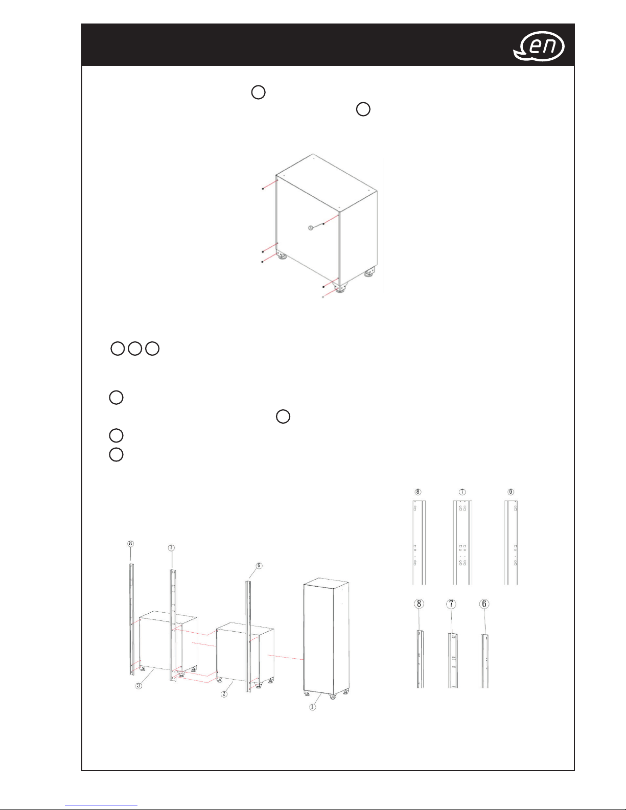
Step 1................................................................................ 9
Step 2.............................................................................. 10
Step 3....................................................................... 10 - 11
Step 4.............................................................................. 11
Step 5.............................................................................. 12
Finish................................................................................ 12
Auspacken....................................................................... 3
Anforderung Montagewerkzeug .................................. 3
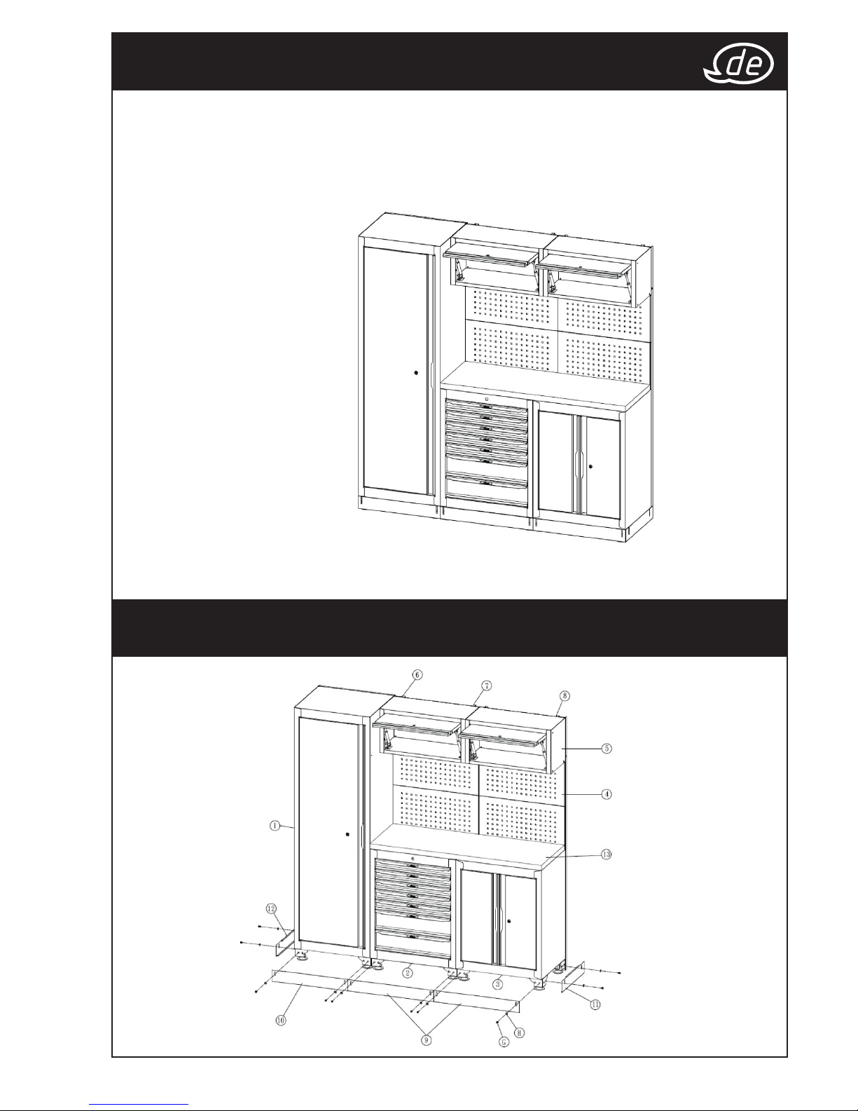
Explosionszeichnung....................................................... 3
Montage
Schritt 1............................................................................. 4
Schritt 2............................................................................. 5
Schritt 3.......................................................................... 5-6
Schritt 4............................................................................. 6
Schritt 5............................................................................. 7
Fertig................................................................................. 7

3
1. Beim Auspacken der Einheit sicherstellen, dass deren Oberseite nach oben weist. Keine
spitzen Werkzeuge zum Auspacken verwenden. Die Einheit nach dem Auspacken vorsichtig
auf Beschädigungen prüfen, die beim Transport entstanden sein könnten. Prüfen, ob sich
Teile gelockert haben, fehlen oder beschädigt sind. Transportschäden sind gegenüber dem
Spediteur geltend zu machen.
Anforderung Montagewerkzeug
Für die Montage der Werkbank wird Folgendes benötigt:
Kreuzschlitzschraubendreher PH2 und 10-mm-Maulschlüssel.
Auspacken
Explosionszeichnung

4
Schritt 1
1. 6 Kreuzschlitzschrauben M6
A
an der Rückseite zur späteren Befestigung der Abstützung
anbringen. Die Kreuzschlitzschrauben M6
A
nicht vollständig anziehen. Soweit anziehen,
dass noch etwa 3 bis 5 Schraubenumdrehungen zum späteren Anbringen der Halterung
verbleiben.
2.
Werkbank am gewünschten Ort aufstellen und die Halterung ( 6, 7, 8)
wie im Diagramm dargestellt unten anbringen.
Die Halterung wie unten markiert an der richtigen Position anbringen.
DieHalterungensindbeschriftetundkönnendadurchleichtidentiziertwerden.
6Die rechte Halterung ist passend für die rechte Seite der Werkbank.
SiebendetsichanderSeitedesWandschranks 1.
7Die mittlere Halterung ist passend für die mittlere Position der Werkbank.
8Die linke Halterung ist passend für die linke Seite der Werkbank.

5
Schritt 2
1. Lochwand 4wie im Diagramm dargestellt an der Halterung befestigen.
Schritt 3
1. 4 Kreuzschlitzschrauben M6 Awie unten dargestellt ( 6, 7, 8) oben an der
Halterung anbringen. Die Kreuzschlitzschrauben M6 Anicht vollständig anziehen.
Soweit anziehen, dass noch etwa 3 bis 5 Schraubenumdrehungen zum späteren
Anbringen der Schrankeinheit 5verbleiben.
2. Schrankeinheit anheben 5und auf die Kreuzschlitzschraube M6 A
an der Halterung ( 6, 7, 8) hängen.
3. Die oberen Schrauben vollständig anziehen und die übrigen 4 Kreuzschlitzschrauben
M6
Avon der Innenseite der Schrankeinheit 5an die Halterung ( 6, 7, 8)
schrauben, um die Statik sicherzustellen.

6
Schritt 3
Schritt 4
1.
Kreuzschlitzschraube M6 Aund Mutter Bverwenden, um die beiden
Schrankeinheiten 5und den Wandschrank 1miteinander zu verbinden.
2. Sechskantschraube M6 C, D, Everwenden, um den Schrank 2, 3und
den Wandschrank 1wie im Diagramm dargestellt miteinander zu verbinden.

7
198 cm
48 cm
64 cm
34 cm
30 cm
60 cm
196 cm
52,5 cm
Max.
20
Max.
20
Max.
25
1. Frontblenden 9, 10 und Seitenblenden 11 ,12 wie im Diagramm dargestellt mit
Schrauben
Gund Distanzscheiben Ham Werkbanksockel anbringen.
2. Holzplatte 13 aufdieArbeitsächelegen.ObersteSchubladeausdemSchrank 2
entfernen und Tür des Unterschranks 3öffnen, um die Holzschrauben Fvon
Innen in die Holzplatte einzuschrauben.
Schritt 5
Fertig
Herzlichen Glückwunsch! Sie haben die Werkbank erfolgreich montiert.
7x
569 x 398 x 75 mm
1x
569 x 398 x 154 mm
25
kg
8x
72
kg 500
kg

8
Unpacking
Exploded Drawing
1. When unpacking unit, please ensure the unit is to face up, please don‘t use sharp-pointed
tools for unpacking. After unpacking unit, inspect carefully for any damage that may
have occurred during transit. Check for loose, missing, or damaged parts. Shipping
damage claim must be filed with carrier.
Assembly Tool Request
To assemble the workstation, you will need a
Phillips Screwdriver PH2 and Open End Wrench 10mm.

9
Step 1
1. Apply 6pcs Phillips M6 Screw
A
on back side of the storage in order to fix with Support
Bracket later. Do not tighten the Phillips M6 Screw
A
completely.
Have about 3-5 screw thread left in order to apply Support Bracket later.
2.
Move storages to the desired location and start to apply the Support Bracket
( 6,7,8) onto it as below diagram. Apply the Support Bracket onto correct
location as marked below. Support Bracket will have labeling on it for easy
identication.
6RightSupportBracketistforRightEndsideofWorkstation.
It is on the side of Wall Cabinet 1.
7MiddleSupportBracketistforMiddlepositionoftheWorkstation.
8LeftSupportBracketistforLeftEndsideofWorkstation.

10
Step 2
1. Apply the Perforated Panel 4to the Support Bracket as below diagram.
Step 3
1. Apply 4pcs Phillips M6 Screw Aon the top of the Support Bracket ( 6,7,8)
as marked below.
Do not tighten the Phillips M6 Screw Acompletely. Have about 3-5
screw thread left in order to apply Cupboard Unit 5later.
2. Lift and hook the Cupboard Unit 5to the Phillips M6 Screw Aon the
Support Bracket ( 6,7,8).
3. Tighten completely the top screws and apply remaining 4pcs Phillips
M6 Screw Afrom inside the Cupboard Unit 5to the Support Bracket
( 6,7,8) to secure the structure.

11
Step 3
Step 4
1.
Use Phillips M6 Screw Aand Nut Bto link between the 2 Cupboard Unit 5
and Wall Cabinet 1.
2. Use Hex Bolt M6 Screw C,D,Eto link between the Cabinet 2,3and Wall
Cabinet
1as below diagram.

198 cm
48 cm
64 cm
34 cm
30 cm
60 cm
196 cm
52,5 cm
Max.
20
Max.
20
1. Apply Front Covers 9,10 and Side Covers 11 ,12 into storage stand with screws G
and washer Has below diagram.
2. Place the Wooden Top 13 on the work surface. Remove the top drawer on the
Cabinet
2and open the door of the Closet Cabinet 3to screw in the Wooden
Screws
Ffrom inner side into the wood plate.
Step 5
Finish
ViGOR GmbH • ;Am Langen Siepen 13-15 • 42857 Remscheid • GERMANY
[
+49 (0) 21 91 / 97 95 •
\
+49 (0) 21 91 / 97 96 00 •
]
^
vigor-equipment.com
V6000-3AHII.11.2016/∞Ho/114
Congregations the workstation is successfully installed.
Max.
25
7x
569 x 398 x 75 mm
1x
569 x 398 x 154 mm
25
kg
8x
72
kg 500
kg
Table of contents
Languages:
Popular Indoor Furnishing manuals by other brands

Steelcase
Steelcase 462 Leap V2 quick start guide

Furniture of America
Furniture of America CM3781SC-2PK Assembly instructions

Wampat
Wampat W02D2082W Assembly instructions

John Lewis
John Lewis 82006902 quick start guide

Forward
Forward Brilliant Assembly instructions

Classic Exhibits
Classic Exhibits visionary DESIGNS MOD-1181 Assembly