Viking Range 5 Series VGC Instructions for use

Installation/
Use & Care
MANUAL
5 SERIES
Outdoor Gas Grills
VQGI5301, VQGI5361, VQGI5421, VQGI5541
VQGFS5301, VQGFS5361, VQGFS5421, VQGFS5541

2
|INSTALLATION / USE & CARE
WARNINGS
WARNING
This product complies with ANSI standard Z21.58/CSA 1.6 latest
edition and has been tested and approved by Intertek.
To obtain replacement parts or service contact:
Viking Range, LLC
Preferred Customer Service
111 Front Street
Greenwood, Mississippi 38930
Service: (888) 845-4641
• Never use dented, rusty or damaged propane cylinders. Never store additional or empty propane cylinders in the
grill cabinet or in the vicinity of this or any other appliance. Do not store propane cylinders indoors or on their
sides.
• Children should never be left alone or unattended in an area where a grill is located. Place your grill well away from
areas where children play. Do not store items that may interest children in or around the grill, in the cart, or in the
masonry enclosure.
• Never move the grill when hot. When in use, portions of the grill are hot enough to cause severe burns.
• Always maintain the required clearances from combustibles as detailed. The grill is designed for outdoor use only.
Never use in a garage, building, shed, breezeway, or other enclosed area. Do not use this grill under any unprotect-
ed overhead combustible construction.
• Gas grills are not designed or certied for and are not to be installed in or on recreational vehicles, portable trailers,
boats or any other moving installation.
• Always have an ABC Fire Extinguisher accessible — never attempt to extinguish a grease re with water or other
liquids.
• Storing your grill: Store your grill in a well-ventilated area. If stored indoors, detach and leave L.P. cylinder outdoors
in a well-ventilated area away from heat and away from where children may tamper with it.
• Keep any electrical supply cord and the fuel supply hose away from any heated surfaces. Electrical cords should be
placed away from walkways to avoid tripping hazard.
• Do not repair or replace any part of the grill unless specically recommended in this manual. Other service should
be performed by a qualied technician.
• If the grill is installed by a professional installer or technician, be sure that he/she shows you where your gas supply
shut-o is located. All gas lines must have a shut-o that is readily and easily accessible. If you smell gas, check for
gas leaks immediately. Check only with a soap and water solution. (See INDEX: “Leak Testing”for further details.)
Never check for gas leaks with an open ame.
• Inspect the L.P. gas supply hose prior to each use of the grill. If there is evidence of excessive abrasion or wear, or
the hose is cut, it must be replaced before using the grill.
• Never remove the grounding prong from the plug or use this product with an ungrounded, 2-prong adapter.
• Installation must conform with local codes or, in the absence of local codes, with either the National Fuel Gas Code,
ANSI Z223.1/NFPA 54, Natural Gas and propane Installation Code, CSA B149.1, or Propane Storage and Handling Code,
B149.2, in Canada.
THIS MANUAL MUST REMAIN WITH THE PRODUCT OWNER FOR FUTURE REFERENCE.

INSTALLATION / USE & CARE |3
WARNINGS
READ THIS MANUAL CAREFULLY and completely before using your grill to reduce the risk of:
1. Fire
2. Burn hazard, personal injury or property damage
3. Ruined steaks or other unpleasant cooking experiences
4. Unapproved installation or servicing.
THIS PRODUCT IS DESIGNED FOR OUTDOOR USE ONLY. Improper installation, adjustment, alteration, service or mainte-
nance can cause property damage, injury or death.
Read this manual thoroughly before installation, use, or servicing of this product.
IF YOU SMELL GAS:
1. Shut o all gas supply lines to the grill.
2. Extinguish any open ames.
3. Carefully open the lid. Remember, it may be ex-
tremely hot!
4. If odor continues, keep everyone away from the
grill and immediately call your gas supplier or your
re department.
1. DO NOT store or use gasoline or other ammable
vapors and liquids in the vicinity of this or any
other appliance.
2. An LP cylinder not connected for use shall not be
stored in the vicinity of this or any other appli-
ance.
WARNING
DANGER
WARNING

4
|INSTALLATION / USE & CARE
WARNINGS
WARNING
STATE OF MASSACHUSETTS
1. Massachusetts requires all gas be installed using a plumber or gas tter carrying the appropriate Massachusetts
license.
2. All permanently-installed natural gas or propane installations require a “T” handle type manual gas valve be installed in
the gas supply line to this appliance.
3. This does not apply to portable propane installations using a 20 pound cylinder.
1. The outdoor cooking gas appliance and its individual shuto valve must be disconnected from the gas supply piping
system during any pressure testing of that system at test pressures in excess of 0.5 psi (3.5 kPa).
2. The outdoor cooking gas appliance must be isolated from the gas supply piping system by closing its individual
manual shuto valve during any pressure testing of the gas supply piping system at test pressures equal to or less than
1/2 psi (3.5 kPa).
WARNING
1. Always maintain the required clearances from combustible construction as detailed. The grill is designed for outdoor
use only. Never use in a garage, building, shed, breezeway or other enclosed area. This grill shall not be used under
any unprotected overhead combustible construction.
2. Gas grills are not design certied for and are not to be installed in or on recreational vehicles, portable trailers, boats
or any other moving installation.
3. Keep any electrical supply cord and the fuel supply hose away from any heated surfaces. Electrical cords should be
placed away from walkways to avoid creating a tripping hazard.
4. Do not repair or replace any part of the grill unless specically recommended in this manual. Other service should be
performed by a qualied technician.
5. All gas lines must have a shut-o that is readily and easily accessible. Be sure the owner knows where the shut-o is
located. If you smell gas, check for gas leaks immediately. Check only with a soap and water solution. Never check for
gas leaks with an open ame. (See INDEX:“Leak Testing” for further details.)
6. Never locate the grill under a roof or overhang, in a building, garage, shed or other such enclosed area.
7. Never locate the grill under unprotected combustible construction.

INSTALLATION / USE & CARE |5
BEFORE YOU START 6
If Shipment Arrives Damaged 6
Important Notes 6
SPECIFICATIONS & INSTALLATION 8
UNPACKING & ASSEMBLY 14
GAS CONNECTIONS 16
Natural Gas 16
LP Gas 17
Gas Conversion Kits 18
ELECTRICAL CONNECTIONS 20
FINAL CHECKS 21
Leak Testing 21
CHECKLIST BEFORE EACH USE 23
A MESSAGE TO OUR CUSTOMERS 23
IMPORTANT SAFETY PRECAUTIONS 23
GRILLING IN WINDY CONDITIONS 25
USING YOUR GRILL 26
Pre-Grill Checklist 26
Lighting your Grill 27
Basic Grilling 29
Using the ProSear™ Burner 30
Using the Rotisserie Burner 31
Using the Smoker Box 32
CLEANING YOUR GRILL 33
TROUBLESHOOTING YOUR GRILL 35
Potential Problems 36
CONTACTING CUSTOMER SERVICE 39
VIKING RANGE, LLC OUTDOOR WARRANTY 40
WIRING SCHEMATICS 41
30 Rotisserie Grill 41
36 & 42 Rotisserie Grill 42
54 Rotisserie Grill 43
TABLE OF CONTENTS

6
|INSTALLATION / USE & CARE
VISIBLE LOSS OR DAMAGE
Be certain any visible damage to the carton is noted on freight
bill or express receipt and signed by the person making delivery.
FILE CLAIM FOR DAMAGES IMMEDIATELY, regardless of extent of
damage.
CONCEALED LOSS OR DAMAGE
If damage is unnoticed until the grill is unpacked, notify the
transportation company or carrier immediately and le a
“concealed damage”claim with them. This should be done
within (15) days of the date delivery is made to you. Be sure
to hold on to the container for inspection. We cannot assume
responsibility for damage or loss incurred in transit. (See INDEX:
“Obtaining Service”for further details.)
Installation into a combustible enclosure requires an insulated jacket accessory. DO NOT REMOVE BRACKET OR INSTALL
UNIT without use of the insulated jacket. Doing so may result in a re, injury or property damage. Bracket must be
removed to complete install with insulated jacket.
Insulated jackets may be ordered at parts@middlebyresidential.com or phone 888-845-4641 press 1.
Please have grill model and serial available when ordering.
BEFORE YOU START
WARNING
IF SHIPMENT ARRIVES DAMAGED
I
MPORTANT NOTES
WHERE’
S
THE WIND
?
W
hen selectin
g
a suitable location, consider important factors
such as exposure to the wind and foot-trac patterns
.
I
f
you have a
f
reestanding grill, position it so the prevailing wind
blows into the
f
ront control panel (at your back when grilling),
supportin
g
the proper
f
ront-to-rear air
ow
.
Bui
l
t-in gri
ll
s
l
ocate
d
in areas wit
h
prevai
l
ing win
d
s s
h
ou
ld
b
e
protecte
d
b
y a win
d
b
arrier.
W
in
d
s
h
itting t
h
e
ba
c
k
of the grill directly may cause problems,
k
as we
ll
as win
d
bl
owin
g
a
l
on
g
t
h
e
h
oo
d
g
a
p
.
H
O
W L
O
NG I
S
Y
OU
R R
U
N
?
Keep all gas supply lines as short as possible because gas lines
lose
p
ressure over distance and with each elbow and tee that
is added. This drop in pressure aects
g
rill performance. (See
INDEX:“Gas Suppl
y
Line Runs”for further details.
)
ARE YOU “ONTHELEVEL”?
Proper levelin
g
durin
g
installation is critical. A
g
rill that is out
of level will cause erratic burner combustion and inecient,
uneven heatin
g
. A carpenter’s spirit level should be used to level
the
g
rill both front-to-back and side-to-side
.
I
f
the
oor is uneven or has a decided slope, re-leveling may be
required each time
y
ou move a
f
reestanding unit
.
O
O
bt
a
ai
ni
ng
g
S
er
r
vice for
further
d
de
ta
a
ils.)
e
ep
p
a
g
g
as s
up
py esas s
o
o
tasposs
b
ebec
a
au
se gas es
Be sure wind doesn’t blow into the hood gap.

INSTALLATION / USE & CARE |7
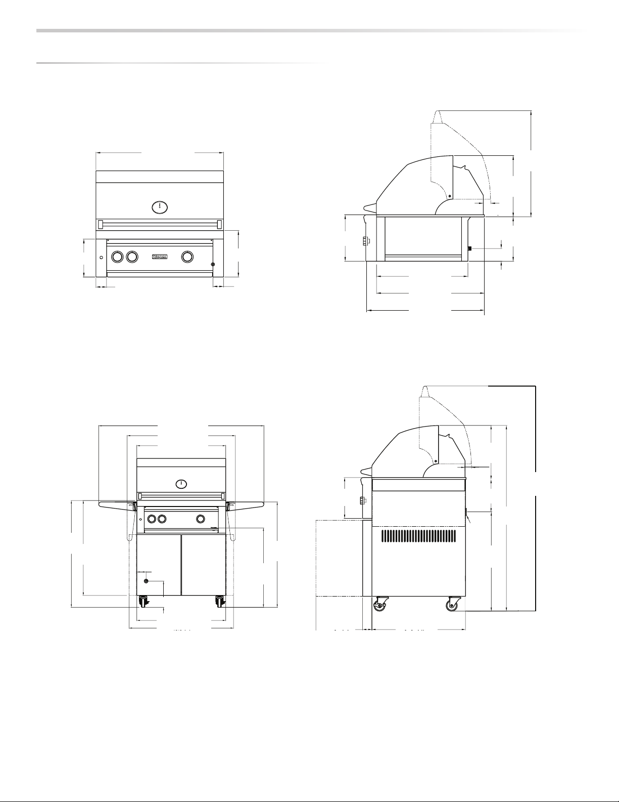
BUILTIN INSTALLATIONS
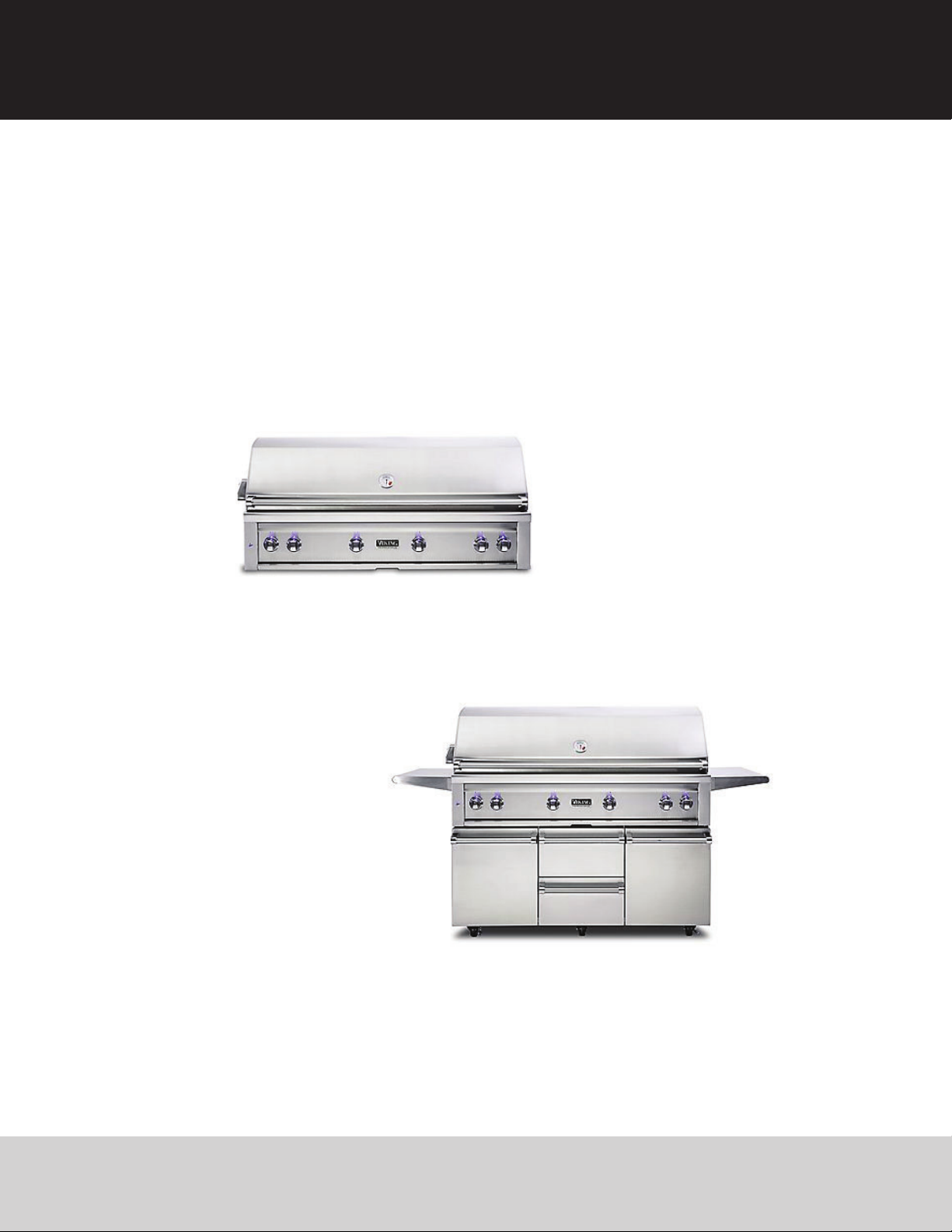
This built-in grill is designed for easy installation into masonry
enclosures.
NOTE: Built-in grills are intended either for installation in a built-
in enclosure constructed of non-combustible materials or for an
installation in a built in enclosure constructed of combustible
material when installed with a insulating jacket).
For non-combustible applications, the grill drops into the
opening shown in the cutout detail drawing (See INDEX:“Gas
Requirements”) and hangs from its counter-top trim. A deck is
not required to support it from the bottom.
When using the insulated jacket in a combustible enclosure, the
jacket must be supported from the bottom by a ledge on each
side or a full deck beneath the jacket.
(See INDEX: “Gas Requirements”) Pay special attention to the
provisions shown for gas line hook-up.
The enclosure should have ventilation holes to prevent gas
build-up in the event of a leak. The deck ledges and counter
should be at and level. (refer to ANSI Z21.58 Standard for
Outdoor Cooking Gas Appliances, Section 1.7 Enclosures For
Self Contained LP-Gas Supply Systems)
This grill requires that a 120 volt, 60 hertz, 15 amp GFI certied
outlet be installed by a qualied electrician.
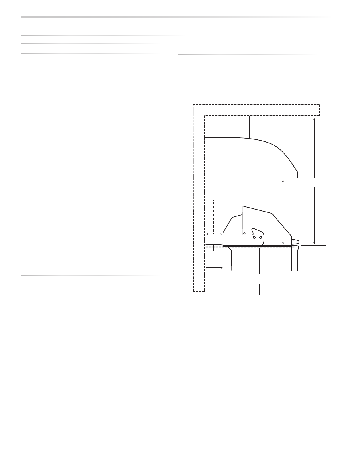
CLEARANCE TO COMBUSTIBLE MATERIALS
Minimum clearance from the sides and back of the grill to
adjacent combustible construction below the counter top
surface is 12”from the sides and 6 1/4”from the back of the
hood.
Minimum clearance from sides and back of grill to adjacent
combustible construction extending above the counter top
surface is 12”from the sides and 6 1/4”from the back.
Do not use this appliance under unprotected overhead
combustible surfaces.
A minimum of 6”of clearance is needed on the left side of the
grill above the counter top for the motor and skewer.
If the grill is to be placed into a combustible enclosure, an
approved insulated jacket is necessary and is available only
from your Viking Range, LLC dealer. Insulated jackets have been
designed and tested specically for your grill.
REAR HOOD CLEARANCE
A 3 inch clearance is required behind the grill to allow the front
hood to open.
The grill exhausts combustion products and cooking greases
to the back. Never locate the grill where this exhaust will be
dicult to clean.
OVERHEAD PROTECTION AND EXHAUST REMOVAL
If installed under any combustible construction the cooking
area over the grill must be covered with an exhaust hood. The
hood must provide 3 - 6”of overhange on all exposed sides. The
exhaust hood shall provide no less than 1,200 CFM for proper
exhaust ventilation. The hood must be approved for outdoor
installation and provided with a dedicated GFCI protected
branch circuit
M
Mi
ilfth
id
d
dbkft
h
ill t
C
CL
EA
A
RA
N
NC
E
T
TO
COMBUST
IB
LE
MAT
ER
IALS
B
EF
O
RE Y
OU
S
TART
...
c
o
n
t
in
u
e
d
Vent Hood
Overhead Construction
R
e
a
r
W
a
l
l
3” overhang on left and right side of grill
36” Minimum
6’ Minimum to
non-combustible
6 1/4” Clearance from the
grill back to above
counter combustibles
3”
Minimum
hood
clearance
12” clearance to combustibles from
surface level right/left/below
Combustible overhead
construction requires a
vent hood
Non-combustible overhead
construction a vent hood is
highly recommended
6 1/4”
Minimum
clearance
to combustibles

8
|INSTALLATION / USE & CARE
The guides, measurements and dimensions detailed below are designated to assist you with planning your outdoor kitchen.
NOTE: Due to continuing product innovation, specications are subject to change without notice.
IMPORTANT: Please reference the Care & Use / Installation manual for details on gas plumbing requirements, electrical specications and the proper
installation of your outdoor kitchen equipment. This manual can be downloaded from our website at www.vikingrange.com.
GRILLS
MODEL A B C
VQGI5301 29.00 10.88 24.50
VQGI5361 35.00 10.13 22.00
VQGI5421 41.00 10.88 24.50
VQGI5541 53.00 10.88 24.50
COMPLEMENTARY PRODUCTS
SIDE BURNERS
MODEL A B C
VQGSB5131 12.13 10.63 24.50
VQGPB5201 19.00 10.63 22.00
WARMING DRAWERS
MODEL A B C
VQEWD5301 28.50 10.00 20.50
VQEWD4201 40.25 19.38 24.50
WITH INSULATED JACKET INSTALLED
MODEL A B C
VIJ5301 36.00 11.63 26.50
VIJ5361 42.00 11.63 24.00
VIJ5421 48.00 11.63 26.50
VIJ5541 60.00 11.63 26.50
S
PE
C
IFI
C
ATI
O
N
S
&
IN
S
TALLATI
ON
I
nstallation into a combustible enclosure requires
a
n insulated jacket accessor
y
. Not installing an
i
nsulated jacket could result in a
re, injur
y
or propert
y
d
amage. Insulated jackets ma
y
be ordered at
parts@
p@
middlebyresidential.com
y
or phone 888-845-4641 press 1.
P
lease have
g
rill model and serial available when orderin
g.

INSTALLATION / USE & CARE |9
5”
(12.7 cm)
4.5”
(11.4 cm)
3”
(7.6 cm)
AA
B
C
COUNTER TOP NOTCH DETAIL
Only required if island counter top overhangs the face of the island
MAXIMUM RUNS FOR ALL
APPLIANCES ON SUPPLY LINE
Run Length 3/4”
Pipe (in feet)
Max BTU for all
Appliances on line
10 360,000
20 245,000
30 198,000
40 169,000
50 150,000
60 135,000
70 123,000
80 115,000
MODEL-SPECIFIC BTU OUTPUTS & MAX. RUNS FOR APPLIANCES
MODELSPECIFIC BTU OUTPUTS
MODEL H BURNER (Btu) ROTISSERIE (Btu) PROSEAR™ (Btu) TOTAL INPUT
VQGI5301/VQGFS5301 (N/L)SS 1 @ 25,000 1 @ 14,000 1 @ 21,000 60,000 Btu/Hr
VQGI5361/ VQGFS5361 (N/L)SS 2 @ 25,000 1 @ 14,000 1 @ 21,000 85,000 Btu/Hr
VQGI5421/ VQGFS5421 (N/L)SS 2 @ 25,000 1 @ 16,000 1 @ 21,000 87,000 Btu/Hr
VQGI5541/ VQGFS5541 (N/L)SS 3 @ 25,000 2 @ 14,000 1 @ 21,000 124,000 Btu/Hr
SPECIFICATI
O
NS
&
INSTALLATI
ON

10
|INSTALLATION / USE & CARE
D
IMENSI
O
NS
30"
11"
9"
REAR
MANIFOLD
LOCATION
21
/2"21
/2"253/8"
277
/8"
13/4"
211
/2"
101/2"
141/2"
253
/16"
11"
3"
30"
32"
36" 351/2"
361
/2"
553/4"
31/8"
87
/8"
263/4
30"
35
1
/4
"
REAR CORD
LOCATION
11"
GAS
EXIT
50"
CORD
141/2"
13/4"
83/4"
263/4"
2
1
/2
"
251/4
"
6011
/16"
87
/8"
30”
(76.2 cm)
9” (22.9 cm) 11” (27.9 cm)
11” (27.9 cm)
2½” (6.4 cm) 2½” (6.4 cm)
25/”
(640 cm)
14½”
(36.8 cm)
10½”
(26.7 cm)
3” (7.6 cm)
1¾”
(4.4 cm)
Rear Manifold
Location
21½”
(54.6 cm)
25/”
(26.7 cm)
27/”
(70.8 cm)
30” (76.2 cm)
36½” (92.7 cm)
55¾” (141.6 cm)
32”
(81.3 cm)
36”
(91.4 cm) 35½”
(90.2 cm)
26¾”
(67.9 cm)
30” (76.2 cm)
35¼
”
(89.5 cm)
3/”
(7.9 cm)
8/” (9.8 cm)
2½”
(6 4 cm)
25¼”
(64 1 )
26¾”
(67.9 cm)
50”
(127.0 cm)
60/”
(154.1 cm)
14½”
(36.8 cm)
8¾”
(22.2 cm)
1¾”
(4.4 cm)
11”
(27.9 cm)
V
Q
GI5301
V
Q
GF
S
530
1

INSTALLATION / USE & CARE |11
DIMENSI
O
NS
REAR CORD
LOCATION
GAS
EXIT
87/16"
9” (22.9 cm) 11” (27.9 cm)
1/” (2.9 cm) 2½” (6.4 cm)
Rear Manifold
Location
36” (91.4 cm)
11” (27.9 cm)
19”
(48.3 cm)
22/”
(58.1 cm)
25/”
(64.5 cm)
14/”
(37.8 cm)
23½”
(59.7 cm)
9/”
(25.1 cm)
3” (7.6 cm)
1¾”
(4.4 cm)
32”
(81.3 cm)
36”
(91.4 cm)
36” (91.4 cm)
42½” (91.4 cm)
61¾” (108.0 cm)
35½”
(90.2 cm)
26¾”
(67.9 cm)
26¾”
(67.9 cm)
50”
(127.0 cm)
58/”
(149.1 cm)
11” (27.9 cm)
1¾”
(4.4 cm)
3/”
(7.9 cm)
8/” (9.8 cm)
14/”
(37.8 cm)
V
Q
GI5361
V
Q
GF
S
536
1

12
|INSTALLATION / USE & CARE
DIMENSI
O
N
S
REAR CORD
LOCATION
3/8"
7
13/4"
101/2"
141/2"
253
/16"
11"
3"
11” (27.9 cm)
25/”
(640 cm)
14½”
(36.8 cm)
10½”
(26.7 cm)
3” (7.6 cm)
1¾”
(4.4 cm)
21½”
(54.6 cm)
25/”
(64.5 cm)
27/”
(70.8 cm)
11"
GAS
EXIT
50"
CORD
141/2"
13/4"
83/4"
263/4"
21/2"251/4"
151/8
"
6011
/16"
87
/8"
2½”
(6.4 cm)
21
/
”
25¼”
(64.1 cm)
26¾”
(67.9 cm)
50”
(127.0 cm)
60/”
(154.1 cm)
14½”
(36.8 cm)
8¾”
(22.2 cm)
1¾”
(4.4 cm)
11”
(27.9 cm)
32"
36" 32”
(81.3 cm)
36”
(91.4 cm)
30"
361
/2"
553/4"
42” (106.7 cm)
48½” (123.2 cm)
67¾” (172.1 cm)
35½”
(90.2 cm)
26¾”
(67.9 cm)
1/”
(3.0 cm)
6/”
(15.7 cm)
42” (106.7 cm)
44/ ” (113 3cm)
9” (22.9 cm) 11” (27.9 cm)
2½” (6.4 cm) 2½” (6.4 cm)
Rear Manifold
Location
42” (106.7 cm)
V
Q
GFS542
1

INSTALLATION / USE & CARE |13
DIMENSI
O
NS
(
DOORS OPEN AT 90°
)
GAS EXIT
REAR
3/8"
7
13/4"
101/2"
141/2"
253
/16"
11"
3"
11” (27.9 cm)
25½”
(648 cm)
10/”
(25.9 cm)
3” (7.6 cm)
1¾”
(4.4 cm)
21½”
(54.6 cm)
25/”
(26.7 cm)
27/”
(70.8 cm)
11"
(
DOORS OPEN AT 90°
)
GAS
EXIT
50"
CORD
141/2"
13/4"
83/4"
263/4"
21/2"251/4"
151/8"
6011
/16"
87
/8"
2½”
(6.4 cm)
18/”
(46.0 cm)
25¼”
(64.1 cm)
50”
(127.0 cm)
60/”
(154.1 cm)
14/”
(37.6 cm)
8/”
(21.9 cm)
1¾”
(4.4 cm)
11”
(27.9 cm)
9” (22.9 cm)
2½” (6.4 cm) 2½” (6.4 cm)
Rear Manifold
Location
54” (137.2 cm)
11” (27.9 cm)
54” (137.2 cm)
60½” (153.7 cm)
79¾” (202.6 cm)
REAR CORD
LOCATION
32”
(81.3 cm)
36”
(91.4 cm)
54” (137.2 cm)
59¼” (150.5 cm) LOCATION
3/”
(7.9 cm)
8/” (9.8 cm)
35/”
(89.4 cm)
26/”
(67.5 cm)
26/”
(67.5 cm)
14/”
(37.6 cm)
V
Q
GI5541
V
Q
GFS554
1

14
|INSTALLATION / USE & CARE
The grill arrives nearly ready to use and requires only minor as-
sembly.
By carefully following the uncrating and unpacking steps, you
will improve your rst experience with the grill.
Shipping weight on smaller units is app. 300 pounds and larger
units may weigh over 500 pounds.
CRATE & CARTON
• IMPORTANT! Do not remove staples around the top of the
carton. These staples hold a wooden pallet in place inside the
carton that protects the unit from damage. Removing these
staples may cause the pallet to fall on the top of grill.
How to Remove the Carton
• Cut the main strap holding the grill to the pallet.
• Remove the staples at the bottom of the carton.
• Lift o the carton.
• With assistance, remove the grill from the pallet and place into
desired location.
The wheels sit down in the gaps of the shipping crate so that
the grill can sit safely and solidly on the crate during shipping.
The grill cannot be slid directly o of the pallet.
One way to safely move the grill o of the pallet is by lifting one
end of the grill high enough to place a ramp under the wheel
and then lift the other end while rolling the grill o of the pallet.
INTERIOR PACKING
Viking Range, LLC uses sturdy tie-down cables and straps to
ensure your grill arrives at your home in the same condition that
it left our factory. BE SURE YOU HAVE REMOVED ALL TIE DOWNS
BEFORE USING YOUR GRILL.
• Remove the white accessory box and wood packing, the grill
racks, and remove any loose items from the rebox.
• Carefully cut the cable ties securing the warming rack and
rotisserie spit (if equipped).
• Cut the strapping that secures the briquette trays and care-
fully lift them out, front rst.
Make sure you remember to remove the tie-downs on the burn-
ers.
• On ProSear™ models, cut and remove ties from the burner
partition on the left side of the ProSear™ burner.
• Ensure that all burners are properly seated on the burner valve
orice and sitting level with the legs in the frame slots and no
side-to-side movement.
U
NPACKING
&
ASSEMBLY
Use two or more people to move or install this unit.
Failure to follow this instruction can result in back or
other personal injuries.
WARNING:
EXCESSIVE WEIGHT HAZARD!
A
RE

INSTALLATION / USE & CARE |15
Inside View, Orice all the
way into venturi
Heat Shield Removed,
Orice/Venturi Position
Legs in slot
Burner sitting at
Orice all the way
into the venturi
U
NPA
C
KING
&
A
SS
EMBLY
...
co
n
t
in
u
e
d

16
|INSTALLATION / USE & CARE
WARNING
NEVER CONNECT A GAS LINE DIRECTLY TO THE GRILL. A PRESSURE REGULATOR MUST BE INSTALLED ON ALL GAS EQUIP
-
MENT. ALL LOCAL CODES REQUIRE THAT THE PRESSURE REGULATOR SUPPLIED WITH YOUR GRILL IS USED. REMOVING OR
FAILING T
O
IN
S
TALL THE PRE
SS
URE REGULAT
O
R
C
AN RE
S
ULT IN FIRE AND
S
ERI
O
U
S
PER
SO
NAL INJURY AND WILL V
O
ID THE
WA
RR
ANTY
.
The grill is factory set to use either propane (LP) or natural gas
(NAT). It is critical that the gas you use matches that which the
grill was set up for. You can verify that by checking the rating
plate.
The Rating plate lists serial numbers, model numbers and gas type. This
one is underneath the drip tray.
The rating plate is located in one or more of the following
places:
• Attached to the underside of the drip tray
• On the heat shield behind the front panel
Ensure that the gas supplied meets with the minimum pressure
requirements. Do not operate the grill on any gas other than
that for which the grill has been set.
Fuel WC Max Inlet WC Min Under
Full Load
Nat Gas 7 in 4 in
LP 14 in 11 in
Water Column Requirements
Both the regulator and the manifold orices have been tuned
for the type of gas specied on the rating plate.
Converting to a dierent type of gas requires a conversion kit,
available from your dealer and must be installed by a qualied
technician.
Installation must conform with local codes or, in the absence
of local codes, with either the National Fuel Gas Code, ANSI
Z223.1/NFPA 54, Natural Gas and propane Installation Code,
CSA B149.1, or Propane Storage and Handling Code, B149.2, in
Canada.Canadian installations must conform to CGA-B149.1/.2
natural gas/propane installation code. (Canada)
NATURAL GAS
Viking Range, LLC recommends that only qualied professionals
perform the required plumbing on this product.
To ensure satisfactory performance, the gas supply line must be
sized to accommodate the total BTU requirements of all the gas-
red equipment that will be connected to that line.
In no case should pipe less than 3/4” inside diameter or 1” out-
side diameter ever be used to connect this product.
• Calculate the total BTU output of all equipment and refer to
“INDEX: Gas Supply Line Runs”for allowable run distances for
¾ inch pipe. Failure to meet these minimum requirements
may reduce performance of the grill and any other appliances
running on that supply line.
• Always keep supply line runs as short as possible. (See INDEX:
“BTU Output” for specic model outputs)
• A gas shut-o valve must be installed in an easily accessible
location by a qualied plumber.
• Keep threading compound o of the rst two pipe threads to
avoid having any small pieces of compound break loose and
clog a burner valve or orice. Do not use threading compound
on any are ttings.
For built-in installations, it is recommended that any exible
pipe used be kept as short as possible. (See INDEX: “Gas Connec-
tions”for typical permanent hook up.)
GA
S
CO
NNE
C
TI
O
N
S
Keep last two threads
reads
cl
e
an

INSTALLATION / USE & CARE |17
Fo
r freestandin
g
units using natural gas, using a metal ex hose
is rec
o
mmen
d
e
d.
T
his is available at your local hardware store or from your dealer.
LP GA
S
Grills set up
f
or LP gas come equipped with an LP hose/ regula-
tor assembly
f
or connection to a standard 20 lb. LP cylinder.
(
Type 1). All
ttings necessary to attach the assembly to the
g
rill are included.
Permanentl
y
plumbed LP connections, such as those in line with a
b
u
lk
cy
l
in
d
er, require a 4/11 regu
l
ator
.
W
h
en using t
h
e 4/11 regu
l
ator you must ensure t
h
at it is set
f
or the proper
f
uel type. This is done by removing the regulator
c
ap and gasket and looking at the bottom o
f
the plunger to see
what
f
uel type is visible. This is the regulator
f
uel setting. NA
T
is
f
or natural gas and LP is
f
or propane gas. The LP setting can
be
f
urther identi
ed by the large diameter disk on the bottom
of
the plunger. To change
f
rom one gas to the other simply
push the plun
g
er to the side to snap it out of the cap, turn the
plunger so it reads the desired gas t
y
pe on the bottom, and
pus
h
t
h
e p
l
un
g
er unti
l
it snaps
b
ac
k
into p
l
ace in t
h
e cap t
h
en
replace the cap into the re
g
ulator
.
Never connect an unre
g
ulated
g
as line to the
g
rill.
LP C
y
linder Requirements
The LP cylinder must be constructed and marked in accordance
with the specications for LP gas c
y
linders of the U.S. Depart-
ment of Transportation (DOT) and designed for use with a T
y
pe
1 system only.
Cylinders o
f
f
ree standing grills must be secured using the pro-
vided cylinder retention system to avoid accidental movement.
When exchanging
y
our c
y
linder
f
or a re
ll, exchange onl
y
f
or a
Type 1 20lb cylinder with
an over-
ll
p
rotection
d
evice
.
Never use a cy
l
in
d
er wit
h
a
d
amage
d
va
l
ve.
A dented or rust
y
LP c
y
linder ma
y
be hazardous and should be
avoided. If in doubt, have it checked b
y
y
our LP supplier.
Always check
f
or leaks a
f
ter every LP cylinder change. (See
INDEX:“Leak Test”
f
or
f
urther details.)
Always shut o the LP-gas supply at the cylinder when the grill
is n
o
t in
u
se
.
Cy
l
in
d
ers must
b
e store
d
out
d
oors in a we
ll
-venti
l
ate
d
area out
of the reach of children. If
y
our grill is stored indoors, the LP
cy
l
in
d
er must
b
e store
d
outsi
d
e
.
LP C
o
nnecti
o
n
s
Make sure the LP c
y
linder valve is full
y
closed. It is possible for
the valve to be open without releasing gas but, as soon as
y
ou
start connectin
g
the re
g
ulator,
g
as will leak from the connec-
ti
o
n
.
LP cylinder with type 1 valve connection
GA
S
CO
NNE
C
TI
O
N
S
...
co
n
t
in
u
e
d
Do not change the regulator/hose assembly or use
any other assembly than the one supplied with your
grill.
Do not attempt to use a 5LP-A equipped regula-
tor/hose assembly with a standard 510 POL cylinder/
valve assembly.
Do not store a spare LP-gas cylinder under or near
this appliance.
Never ll the cylinder beyond 80 percent full.
If the information above is not followed exactly, a re
causing death or serious injury may occur.
WARNING

18
|INSTALLATION / USE & CARE
GA
S
CO
NNE
C
TI
O
N
S
.
..
co
n
t
in
u
e
d
Insert the regulator inlet into the cylinder valve and turn the
black coupler clockwise until the coupler is hand tight. Do not
over-tighten this connection.
To disconnect the coupler, rst make sure the main cylinder
valve is turned o. Grasp the coupler and turn counter
clockwise. The inlet will then disengage.
Always leak-test the connection after relling or exchanging LP
cylinders. (See INDEX: “Leak Test”for further details.)
GAS LINE PURGING
You should purge the gas line of air before attempting to light
the grill.
• Make sure all grill controls are in the“OFF”position.
• Slowly turn on the main gas supply.
• Push in the rotisserie knob and conrm that the igniter
is glowing. It is furthest from the fuel source and will
completely purge the lines. It will take several seconds for the
burner to light.
• Hold the knob ON for about 20 seconds to allow the air in the
system to purge and the burner to light
• Wait at least 5 minutes after shutting o the control before
attempting to light the burners.
GAS CONVERSION KITS
Gas conversion kits are available from Viking Range to allow
the grill to operate on either Natural gas or LPG. These kits
should be installed by a qualied technician.
The kits come with complete installation instructions. These
instructions should be read completely and fully understood
before installing the conversion kit.
L
P CONVERSION KI
T
NG CONVERSION KI
T
NG AND BULK LP BUILT-IN IN
S
TALLATI
ON
•Shut o the gas suppl
y
at the main valve
.
•If connecting to a bulk propane tank, disconnect the brass
elbow, hose and re
g
ulator
f
rom the
g
rill.
gg
•Remove all ttin
g
s from the
g
rill manifold
.
•Connect the gas supply to the grill as shown in the diagram
on t
h
is pa
g
e
.
•Turn the gas supply on and leak test all connections. (See
INDEX
:
“Le
ak
Test”
fo
r
fu
rt
h
er
d
et
a
i
l
s
.
gy
y
Never r
u
n ex h
o
se
b
ehin
d
the re
bo
x
.
R
u
n the h
o
se
a
t
a
n
an
g
le, strai
g
ht down or out of the back
Inline Regulator
1/2” MxF
Street
Elbow
Angle At Least
20˚ From Horizon
Grill Manifold
1/2” MIP
Fitting
Flexible Gas Line to Inlet

INSTALLATION / USE & CARE |19
NG AND BULK PROPANE CART INSTALLATION
• Shut o the gas supply at the main valve.
• Disconnect all plumbing (if already attached) from the grill and
the gas supply valve.
• Remove all the ttings from the grill manifold.
• Connect the gas supply to the grill as shown in the diagrams
on this page for your gas type.
• Turn the gas supply on and leak test all connections. (See
INDEX: “Leak Test” for further details.)
GA
S
CO
NNE
C
TI
O
N
S
.
..
c
o
n
t
in
u
e
d
LP BOTTLE CART INSTALLATION
• Shut o the gas supply at the main valve.
• Connect the gas supply to the grill as shown in the diagram on
this page for your gas type.
• Turn the gas supply on and leak test all connections. (See
INDEX: “Leak Test” for further details.)
he g
r
ri
ll and
d
iag
ra
a
ms
. (S
ee
e
Grill Manifold with Brass Elbow
Angle At Least
20˚ From Horizon
Regulator
P/N 13053
To Propane Tank
Grill Manifold
Flexible Gas Line to Inlet
Inline
Regulator
1/2’’ Close
Nipple
1/2’’ FIP
Street
Elbow
1/2’’ MIP
Fitting
SIDE BURNER INSTALLATION

20
|INSTALLATION / USE & CARE
Installation requires an outdoor 120VAC 15A GFI (Ground Fault
Interrupter) electrical outlet adjacent to the grill.
The GFI outlet features an internal breaker that reduces shock
hazard. This type of outlet should be installed by a qualied
electrician either inside the island enclosure for built-in units, or
near the location where a free-standing unit will be used.
For built-in grills, the supplied 12VDC should be installed below
the grill within the cabinet enclosure. Select a location where
the transformer is protected against water, heat and physical
damage.
When installing the transformer to the grill be careful to
prevent the wiring and transformer from contacting any hot
surfaces behind or below the grill. It is recommended that the
transformer be located below the grill in a readily accessible
location. Be sure to provide adequate access to facilitate
service if the transformer or connections should need future
maintenance.
If the electrical system fails to operate, a connection may have
come loose in shipping or the GFI may have tripped, requiring a
reset. See the Troubleshooting section for more details.
CONNECTION TO AC
ELE
C
TRI
C
AL
CO
NNE
C
TI
O
N
S
• Product installation must meet local electric codes or, in the absence of local codes, the latest edition of the National
Electrical Code ANSI/NFPA No. 70 or the Canadian Electrical Code CGA 1.6b2005.
• Use only a Ground Fault Interrupter (GFI) protected circuit with this outdoor cooking gas appliance.
• IMPORTANT: When connecting your rotisserie motor, rst connect the motor to the grill and then plug the grill into the
outlet.
• This grill is equipped with a three prong (grounding) electric plug for your protection against shock hazard and must be
plugged directly into a properly grounded three prong outlet. Never cut or remove the grounding prong from this plug.
• Use only extension cords with a 3 prong grounding plug, rated for the power of the equipment, and approved for out-
door use with a “W-A” marking.
• To protect against electric shock, do not immerse any part of the power cord, an extension cord or any plugs in water or
other liquid.
• Unplug the product from the outlet when not in use and before cleaning. Allow it to cool before putting on or taking o
parts.
• Do not let the cord hang over the edge of a table or touch hot surfaces.
• Do not use an outdoor cooking gas appliance for purposes other than intended.
• Do not operate any outdoor cooking gas appliance with a damaged cord, plug, or after the appliance malfunctions or
has been damaged in any manner. Contact the manufacturer for repair.
WARNING: ELECTRICAL GROUNDING
Other manuals for 5 Series VGC
20
This manual suits for next models
8
Table of contents
Other Viking Range Grill manuals
Popular Grill manuals by other brands

Char-Broil
Char-Broil 14202002 Product guide

Char-Broil
Char-Broil 466244011 Product guide

Weber
Weber Summit 56211 owner's guide

Dyna-Glo
Dyna-Glo DGP350NP and User's manual and operating instructions

Tower Hobbies
Tower Hobbies T27011 Safety and instruction manual

Star
Star GRILL EXPRESS GX10IG Specification sheet

Outback
Outback Omega 150 Assembly and operating instructions

Uniflame
Uniflame GBC1405SP owner's manual

Nexgrill
Nexgrill 720-0440-LP Assembly & operating instructions

Captiva Designs
Captiva Designs E02GR010 Use and care guide

Char-Broil
Char-Broil 463243812 Product guide

croydon
croydon SACL-10428-700 instruction manual