Viking DFUR Series Technical manual

USE/INSTALLATION
INSTRUCTIONS
24” W. UNDERCOUNTER/FREESTANDING REFRIGERATed beverage center
Retain for Future Reference
VIKING RANGE CORPORATION
111 FRONT STREET
GREENWOOD, MISSISSIPPI 38930 USA
(662) 455-1200
IMPORTANT - PLEASE READ AND FOLLOW
••Before beginning, please read these instructions completely and carefully.
• Do not remove permanently affixed labels, warnings, or plates from the product. This may void the warranty.
• Please observe all local and national codes and ordinances.
• Please ensure that this product is properly grounded.
• The installer should leave these instructions with the consumer who should retain them for local inspector’s use and
for future reference.
WARNING::
TToorreedduucceetthheerriisskkooffffiirree,,eelleeccttrriiccaallsshhoocckk,,oorriinnjjuurryywwhheennuussiinnggyyoouurrrreeffrriiggeerraatteeddbbeevveerraaggeecceenntteerr,,ffoolllloowwbbaassiicc
pprreeccaauuttiioonnssiinncclluuddiinnggtthheeffoolllloowwiinngg::
•FOR YOUR SAFETY•
DO NOT STORE OR USE GASOLINE OR OTHER FLAMMABLE VAPORS AND LIQUIDS IN THE VICINITY OF THIS OR
ANY OTHER APPLIANCE. THE FUMES CAN CREATE A FIRE HAZARD OR EXPLOSION.
IIttiissyyoouurrrreessppoonnssiibbiilliittyyttoobbeessuurreeyyoouurrrreeffrriiggeerraatteeddbbeevveerraaggeecceenntteerriiss::
•located so the front is not blocked to restrict incoming or discharge air flow.
•properly leveled.
•located in a well ventilated area.
•connected to the proper type of outlet, with the correct electrical supply and grounding. A 115 volt, 60 Hz, 15 amp
fused electrical supply is required. NNOOTTEE::Time delay fuse or circuit breaker is recommended.
•not used by anyone unable to operate it properly.
•used only for its intended purpose.
•properly maintained.
•SAVE THESE INSTRUCTIONS•
DANGER
SUFFOCATION HAZARD
Remove doors from your
old refrigeration unit.
Failure to do so can result
in child entrapment, which
can cause death or brain
damage.
IMPORTANT: Child entrapment and suffocation are not problems of the past. Junked or abandoned refrigerated
beverage centers are still dangerous, even if they will sit for “just a few days.” If you are getting rid of your refrigerated
beverage center, please follow the instructions below to help prevent accidents.
BEFORE YOU THROW AWAY YOUR OLD REFRIGERATED BEVERAGE CENTER:
•Take off the doors.
•Leave the shelves in place so that children may not easily climb inside.
PROPER DISPOSAL OF YOUR OLD refrigerated beverage center
41007774
Rev. B

2
GENERAL INFORMATION
Unpack
1. Remove banding from bottom of carton. Lift carton up and off of the unit.
2. Remove all tape and packaging material from the outside and inside of the cabinet.
3. Keep all carton packaging until your wine cooler has been thoroughly inspected and found to be in good
condition.
AREA REQUIREMENTS
1. Place unit so the front side will be completely unobstructed to provide proper air flow. The unit may be closed in
on the top and three sides, but the front MMUUSSTTBBEEunobstructed for air circulation and proper operation.
Installation should be such that the cabinet can be moved for servicing if necessary.
2. Unit should be in a well ventilated area. Best results are obtained at temperatures between 650F (180C) and 800F
(270C) for built-in models and 650F (180C) and 900F (300C) for freestanding models.
3. Provisions for electricity should be determined before placing unit in proper place.
A
B
C
UNDERCOUNTER CABINET
CUTOUT
AA24” (61.0 cm)*
BBMin. 34 1/8” (86.7 cm)
Max. 35 1/8” (89.2 cm)
CC24” (61.0 cm)
*24” width for cabinet only. If door is
recessed between cabinets, cabinet cutout
must be 24-1/4” (61.6 cm)

3
SPECIFICATIONS/DIMENSIONS
BBaassiiccEElleeccttrriiccDDaattaa
•115 VAC/60 Hz
•Maximum amps - 3.3
•Approximate Shipping Weight - 140 lbs. (63.2 kg)
Min. 34”
(86.4 cm)
Max 35”
(88.9 cm)
with
leveling
legs fully
extended
30 3/4”
(78.1 cm)
23 7/8” (60.6 cm)
47 1/4” (120.0 cm)
22” (55.9 cm)
24 3/8” (61.9 cm)
25 3/8” (64.5 cm)
47 1/4” (120.0 cm)
22” (55.9 cm)
24 3/16” (61.4 cm)
FFrroonnttVViieeww
SSiiddeeVViieeww
DDUUAARR
SSiiddeeVViieeww
DDFFUURR
(To front of locally
supplied custom panel)

4
custom wood frame installation instructions
((DDFFUURRMMooddeellss))
NNOOTTEE::WWeeiigghhttooffwwooooddppaanneellmmuussttnnootteexxcceeeedd2200llbbss..
WWooooddSSccrreewwss
1. A #8 pan head wood screw should be used to properly secure the wood frame. A total of 10 screws will be needed
for a 3 1/2” (8.9 cm) kickplate or 8 screws for a 4” (10.2 cm) kickplate.
2. Only use pan head screws.
3. DDOONNOOTTselect a screw that is longer than the wood thickness at
the screw locations.
4. Use recommended pilot holes for the frame material. (See chart)
WWoorrkkiinnggMMaatteerriiaallWWooooddSSccrreewwSSiizzee--##88
Hardwood 3/32 (0.24 cm)
Softwood 5/64 (0.20 cm)
AAsssseemmbblliinnggDDoooorrHHiinnggeeBBrraacckkeettss
(Disregard if hinge brackets are already attached)
1. Attach the top and bottom door hinge brackets to the door with the #10-32 machine screws and a 1/8” allen head
driver as shown in Figure 1 below.
2. Press in the shoulder bushings to the top and bottom door hinge brackets. Make certain that the shoulder is to the
outside of the door as shown in Figure 1 below.
3. Test fit the door to the unit to make certain door will hang correctly. The door is hung correctly when the top of the
door is parallel to the top of the unit. (See Figure 2) Adjustments can be made by loosening the door hinge
machine screws and moving the door hinge brackets on the door.
4. Tighten all four (4) machine screws after adjustments have been made.
5. Remove the door from the unit by removing the units top hinge set screw and angling the door off of the bottom
hinge pin.
Figure 1
Figure 2
Shoulder Bushing
Door Hinge Bracket
#10-32 Machine
Screws
Door Hinge
Screw Holes
Door Front
Surface
This surface parallel to the unit.
(Right hinge door shown)
TTyyppiiccaallTTooppaanndd
BBoottttoommDDoooorrHHiinnggee
BBrraacckkeettAAsssseemmbbllyy

5
1/4” x 3/8” Deep hinge screw clearance hole. Locate and drill using
door hinge hole after the door has been aligned to the unit and
when the wood is positioned on door.
1/4” x 3/8” Deep hinge screw clearance hole. Locate and drill using
door hinge hole after the door has been aligned to the unit and
when the wood is positioned on door.
Mounting surface
(Non-face) side Mounting surface
(Non-face) side
5/8”
(1.7 cm) min.
3/4”
(1.9 cm) max
23 7/16” (59.5 cm)
7 13/16”
(18.3 cm) TYP
23/32”
(1.8 cm) TYP
23/32”
(1.8 cm) TYP
1 23/32” (4.4 cm) min.
width to cover door
extrusion
Pre-drilled pilot
holes - 10 places
7 13/16”
(19.8 cm)
TYP
15 5/32”
(38.5 cm)
TYP
22 1/2”
(57.2 cm)
TYP
Mounting surface
(Non-face) side
30 5/16
(77.0 cm)
15 5/8” (39.7 cm)TYP
SSeelleeccttiinnggaannddPPrreeppaarriinnggtthheeWWooooddFFrraammee
FFOORR33--11//22””TTOOEEKKIICCKK
((CCOOVVEERRSSTTHHEEEENNTTIIRREEDDOOOORREEXXTTRRUUSSIIOONN))

6
AAttttaacchhiinnggtthheeHHaannddllee
Attach the handle of your choice by drilling mounting holes through panel. Countersink or counterbore holes from
back side of panel for handle screw heads to be flush.
1/4” x 3/8” Deep hinge screw clearance hole. Locate and drill using
door hinge hole after the door has been aligned to the unit and when
the wood is positioned on door.
5/8” (1.7 cm) min.
3/4” (1.9 cm) max
1/4” x 3/8” Deep hinge screw clearance hole. Locate and drill
using door hinge hole after the door has been aligned to the unit
and when the wood is positioned on door.
Mounting surface
(Non-face) side
Mounting surface
(Non-face) side
Mounting
surface
(Non-face) side
23 7/16” (59.5 cm)
23/32”
(1.8 cm) TYP
1 23/32” (4.4 cm) min.
width to cover door
extrusion
23/32”
(1.8 cm)
TYP
29 13/16”
(75.7 cm)
Pre-drilled pilot
holes - 8 places
15 5/8” (39.7 cm) TYP
7 13/16”
(18.3 cm) TYP
7 13/16”
(19.8 cm)
TYP
15 5/32”
(38.5 cm)
TYP
22 1/2”
(57.2 cm)
TYP
OOPPTTIIOONNAALLFFOORR44””TTOOEEKKIICCKK
TTOOMMAATTCCHHEEXXIISSTTIINNGGCCAABBIINNEETTRRYYTTOOEEKKIICCKKHHEEIIGGHHTT

7
AAttttaacchhiinnggtthheeWWooooddFFrraammeettootthheeDDoooorr
1. If the door is attached to the unit, remove by unscrewing the top allen head set screw at the top hinge. Remove
the door by angling the door off of the bottom hinge pin.
2. Peel back the door gasket to expose the screw holes.
3. Set the wood frame flush to the front of the door in the desired location. Clamp the wood frame to the door if
necessary.
4. Insert the wood screws through the back of the door into the pilot holes in the wood frame and tighten.
5. Reinstall the door gasket by pressing into the door channel. Make certain the corners are inserted fully.
6. Install the door to the unit. Use the supplied plastic washer as shown in the figure below.
7. Realigning the door may be necessary. Any final door adjustments can be made using a 1/8” allen head driver to
adjust the door’s hinges. (See figure below)
8. Attach the door light striker plate as shown using the 5/16” hex or phillips head screws provided. Make certain the
light is able to turn on and off when the door is opened and closed.
9. Attach the door to the unit by reversing step number 1 above.
CAUTION
Door can become
disengaged if washers
are not installed.
CAUTION
Door can become
disengaged if
washers are not
installed.
Cabinet
Hinge
(2) Nylon
hardware
components at
top hinge
Wood
Frame
Door
Hinge
Door
Hinge
Shoulder bushing
3/4” OD x 7/16”
ID Washer
3/4” OD x 1/4”
ID Washer
(3) Nylon hardware
components at
bottom hinge
CAUTION
Door may not swing properly
if all nylon components are
not installed as shown
Bottom Hinge Cover Top Hinge Cover
5/8” x 7/32” ID
washer
Shoulder bushing
Wood
Frame
HHiinnggeeHHaarrddwwaarree
IInnssttaallllaattiioonnDDeettaaiillss
Magnetic
door gasket 3/8” clearance
holes for frame
wood screws -
10 holes
1/8” allen head screws for
hinge adjustment
Rear of Door
Door light striker plate
Bottom of door
Door hinge
adjustment screws
Attached wood frame

8
ELECTRICAL CONNECTION
EElleeccttrriiccaallRReeqquuiirreemmeennttss
A 115 volt, 60 Hz, AC only 15 amp fused electrical supply is required. (A
time delay fuse or circuit breaker is recommended.) It is recommended
that a separate circuit, serving only this appliance, be provided.
••EELLEECCTTRRIICCAALLGGRROOUUNNDDIISSRREEQQUUIIRREEDDOONNTTHHIISSAAPPPPLLIIAANNCCEE..
••DDOONNOOTTUUNNDDEERRAANNYYCCIIRRCCUUMMSSTTAANNCCEESSRREEMMOOVVEETTHHEEPPOOWWEERR
SSUUPPPPLLYYCCOORRDDGGRROOUUNNDDPPLLUUGG..
••DDOONNOOTTUUSSEEAANNEEXXTTEENNSSIIOONNCCOORRDD..
RReeccoommmmeennddeeddGGrroouunnddiinnggMMeetthhooddss
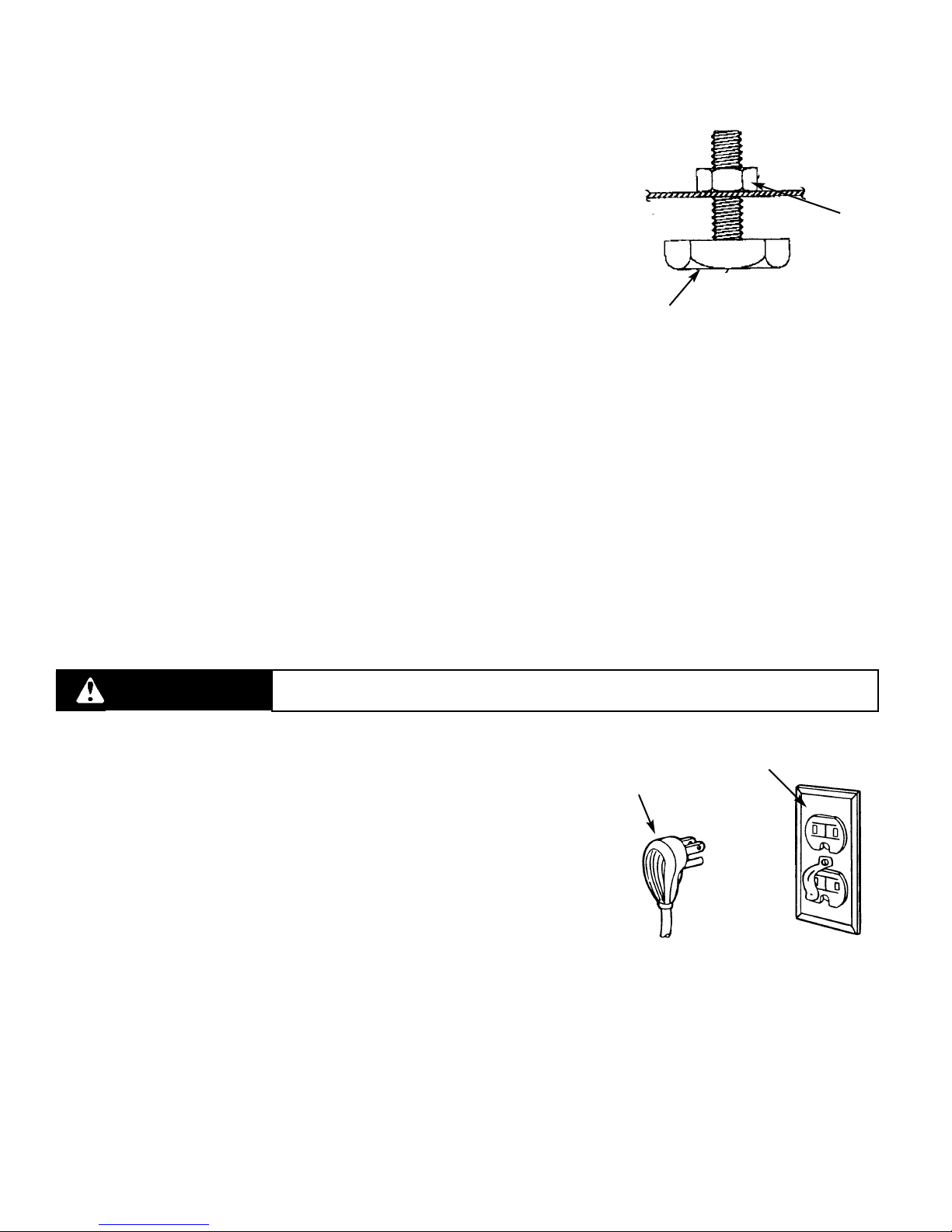
For your personal safety, this wine cooler must be grounded. This
appliance is equipped with a 7’ (2.1 m) power supply cord having a 3-prong grounding plug. To minimize possible shock
hazard, the cord must be plugged into a mating 3-prong grounding type wall receptacle grounded in accordance with the
National Electrical Code and local codes and ordinances. If the circuit does not have a grounding type receptacle, it is the
responsibility and obligation of the customer to exchange the existing receptacle in accordance with the National Electrical
Code and applicable local codes and ordinances. The third ground plug SHOULD NOT, under any circumstances, be cut or
removed. All UL listed refrigerated products are equipped with this type of plug.
Power Supply
with 3-prong
grounding plug
Grounding type wall
receptacle
WARNING ELECTRICAL SHOCK HAZARD
Failure to follow these instructions could result in fire or electrical shock.
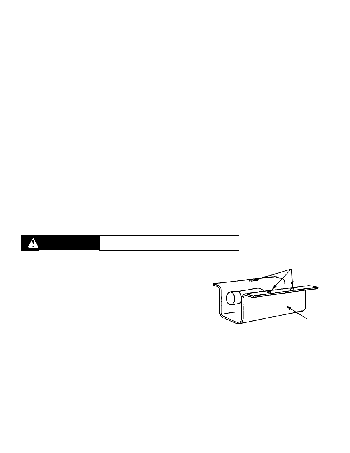
LEG LEVELER INSTALLATION
RReeaaddBBeeffoorreeIInnssttaalllliinnggLLeeggLLeevveelleerrss
WWAARRNNIINNGG::Do not lay unit on top, side, back, or front. If unit is accidentally laid
in any position other than right side up, then the unit must remain in the right side
up position for at least 24 hours before plugging the unit in.
1. Tip unit backwards so there is one foot of clearance on front of the unit. Have
someone to assist you in tilting the unit to prevent it from falling on you while
installing the leg levelers.
2. Screw front two (2) leg levelers into the weldnuts. Leg levelers should be
screwed in until snug.
3. Repeat steps 1 & 2 with the exception of tipping the unit forwards to screw in
the back two leg levelers.
4. The leg levelers are now installed.
5. The unit should be level from front to back and side to side. If floor conditions
do not allow the unit to sit level, adjust the leg leveler by turning the required
leg leveler counter-clockwise to increase the height and clockwise to reduce
the height.
LLeeggLLeevveelleerr
((44))ppeerruunniitt
WWeellddnnuutt
((EEaacchhbboottttoomm
ccoorrnneerrooffuunniitt))

9
WIRING DIAGRAM
UNDERCOUNTER 24” W. REFRIGERATed beverage center
WWAARRNNIINNGG::EELLEECCTTRRIICCAALL
GGRROOUUNNDDIINNGG
IINNSSTTRRUUCCTTIIOONNSS
This appliance is equipped with a
three prong grounding plug for
your protection against shock
hazard and should be plugged
directly into a properly grounded
three prong receptacle. Do not
cut or remove the grounding
prong from this plug.
FINAL PREPARATION
1. Some stainless steel parts may have a plastic protective wrap which must be peeled off. The interior of the unit should be
washed thoroughly with hot, soapy water, rinsed ,and wiped dry to remove film residue and any installation dust or debris
before being used. Solutions stronger than soap and water are rarely needed.
2. All stainless steel parts should be wiped with hot soapy water. If buildup occurs, do not use steel wool, abrasive cloths,
cleaners, or powders. If necessary to scrape stainless steel to remove encrusted materials, soak with hot, wet cloths to
loosen the material, then use a wood or nylon scraper. Do not use a metal knife, spatula, or any other metal tool to scrape
stainless steel; scratches are almost impossible to remove.

10
OPERATING INSTRUCTIONS
Setting the Controls
The total available temperature range of the unit is from 39 - 420F (4.0 - 5.60C) to 54 - 560F (12 - 130C). The higher the number
selected, the cooler the temperature within the unit. To start your refrigerated product, use a screwdriver to turn the control
clockwise to the middle thermostat setting. Allow at least 48 hours for the unit to stabilize before making any adjustments to
the initial setting.
general tips and Suggestions
1. After making a temperature adjustment, allow 24 hours for your refrigerated beverage center to reach the new temperature
setting.
2. The motor will stop and start often. It must do this to maintain the temperature setting.
3. Unplug the unit before working on the electrical system.
4. Exercise caution when sweeping, vacuuming, or mopping near the front of the unit. Damage to the grill and/or light switch
can occur.
Interior Light
The interior light allows you to view the unit’s contents. When the switch is in the “OFF” position, the light will come on only
when the door is opened. In the “ON” position, the light remains on continuously.
LIGHT BULB REPLACEMENT
This unit uses a 15-watt appliance bulb with an intermediate base located
inside the light shield. The light shield is on the back wall of the unit and
is held in place by screws. Remove the three screws and light shield to
remove the light bulb. DO NOT replace the bulb with a bulb higher
than 15 watts.
Light
Shield
Screws
WARNING Failure to disconnect the power cord when changing
the light bulb may result in electrical shock.
ENERGY SAVING TIPS
•Reduce door openings.
•Close the door as soon as you can.
•Keep the condenser coils on bottom of the refrigerated beverage center clean. (See “Cleaning and Maintenance”)
•Adjust the temperature control to a warmer setting when practical.
•Do not put hot foods in the refrigerated beverage center.
•Install unit away from the stove or other heat sources.

11
CLEANING AND MAINTENANCE
Any piece of equipment works better and lasts longer when maintained properly and kept clean.
CCoonnddeennsseerr
The condenser tubing inside the cabinet does not require frequent cleaning; however, satisfactory cooling depends on
adequate ventilation over the coils. Be sure that nothing obstructs the required air flow openings in front of the
cabinet. Spiders and insects can nest in and around the refrigerated beverage center causing damage to the unit.
Frequently brush or vacuum lint and dirt from the condenser coils for efficient performance by unscrewing the grill on
the bottom front of cabinet.
CCaabbiinneett
The cabinet can be washed with mild soap and water and thoroughly rinsed with clear water. Never use abrasive
scouring powders.
IInntteerriioorr
Wash interior compartment with mild soap and water. Do not use abrasive powder, solvent, polish cleaner, or undiluted
detergent.
SSttaaiinnlleessssSStteeeellPPaarrttss
All stainless steel parts should be wiped regularly with hot soapy water. Use a liquid cleaner designed for stainless
steel when soapy water will not do the job. DDoonnoottuusseesteel wool, abrasive cloths, cleansers, or powders. Do not
permit citrus or tomato juice to remain on stainless steel surfaces, as citric acid will permanently discolor stainless steel.
BBrraassssPPaarrttss
CCAAUUTTIIOONN::All brass parts have an epoxy coating. DDOONNOOTTUUSSEEBBRRAASSSSOORRAABBRRAASSIIVVEECCLLEEAANNEERRSSOONNTTHHEEBBRRAASSSS
PPAARRTTSS..All brass parts should be wiped regularly with hot soapy water. When hot soapy water will not do the job, use
every day non-abrasive household cleaners.
GGllaassssDDoooorr
Use a glass cleaner or mild soap and water with a soft cloth to clean the glass door. Do not use any abrasive powders.
On full overlay models, use caution when cleaning near logo area.
PPaaiinntteeddSSuurrffaacceess
Wash with warm soapy water. DDOONNOOTTUUSSEEsteel wool, abrasive cleansers, ammonia, acids, or commercial oven
cleaners which may damage the finish.
DDoooorrGGaasskkeett
The vinyl gasket may be cleaned with mild soap and water, a baking soda and water solution, or a mild scouring
powder.

12
TROUBLESHOOTING CHART
PPrroobblleemmPPoossssiibblleeCCaauussee//SSoolluuttiioonn
Odor in cabinet Interior needs cleaning
Noisy operation/cabinet vibrates Cabinet not level; weak floor
Cabinet light not working Bulb burned out; no power at outlet
Appliance will not run Temperature control to “OFF”; line cord not plugged in; no
power at electrical outlet; house fuse blown
Appliance runs too long Prolonged door openings; control set too cold; condenser
needs cleaning
Moisture collects inside Too many door openings; prolonged door openings; (hot,
humid weather increases condensation)
Moisture collects to outside surface Control improperly set (Hot, humid weather increases
condensation)
Interior too hot/too cold Control improperly set; faulty thermometer; (relocate
thermometer to center of cabinet and recheck)
Record the following information indicated below. You will need it if service is ever required. The serial number and
model number for your refrigerated beverage center is located on the front of the unit at the base of the door frame.
Model Number Serial Number
Date of Purchase Date Installed
Dealer’s Name
Address
IIffsseerrvviicceerreeqquuiirreessiinnssttaallllaattiioonnooffppaarrttss,,uusseeoonnllyyaauutthhoorriizzeeddppaarrttssttooeennssuurreepprrootteeccttiioonnuunnddeerrtthheewwaarrrraannttyy..
TThhiissmmaannuuaallsshhoouullddrreemmaaiinnwwiitthhtthheerreeffrriiggeerraatteeddbbeevveerraaggeecceenntteerrffoorrffuuttuurreerreeffeerreennccee..
SERVICE INFORMATION
It is assumed that your refrigerated beverage center has been properly installed in accordance with all specifications and
local codes and the appliance has been properly grounded. If your refrigerated beverage center should fail to operate,
review the troubleshooting chart before calling for service. You could save the cost of a service call.
If service is required:
1. Call your dealer or authorized service agency. The name of the authorized service agency can be obtained from the
dealer or distributor in your area.
2. Have the following information readily available:
•Model number
•Serial number
•Date of purchase
•Name of dealer from whom purchased
If you are unable to obtain the name of an authorized service agency, or if you continue to have service problems, contact
Viking Range Corporation at (888) 845-4641 or write to:
VVIIKKIINNGGRRAANNGGEECCOORRPPOORRAATTIIOONN
PPRREEFFEERRRREEDDSSEERRVVIICCEE
111111FFrroonnttSSttrreeeett
GGrreeeennwwoooodd,,MMiissssiissssiippppii3388993300UUSSAA

F20275A (PS0104VR)
designer SERIES
BUILT-IN UNDERCOUNTER/FREESTANDING REFRIGERATed beverage center WARRANTY
TTWWOOYYEEAARRFFUULLLLWWAARRRRAANNTTYY
Built-in/freestanding undercounter refrigerated beverage centers and all of their components and accessories, except as detailed below*, are warranted to be free
from defects in material or workmanship under normal household use for a period of two (2) years from the date of original retail purchase. Viking Range Corporation,
warrantor, agrees to repair or replace, at its option, any part which fails or is found to be defective during the warranty period
*Painted and decorative items are warranted to be free from defective materials or workmanship for a period of ninety (90) days from the date of original retail
purchase. ANY DEFECTS MUST BE REPORTED TO THE SELLING DEALER WITHIN NINETY (90) DAYS FROM DATE OF ORIGINAL RETAIL PURCHASE.
SSIIXXYYEEAARRFFUULLLLWWAARRRRAANNTTYY
Any sealed refrigeration system component, as listed below, is warranted to be free from defective materials or workmanship in normal household use during the third
through the sixth year from the date of original retail purchase. Viking Range Corporation, warrantor, agrees to repair or replace, at its option, any part which fails or is
found to be defective during the warranty period.
SSeeaalleeddRReeffrriiggeerraattiioonnSSyysstteemmCCoommppoonneennttss::Compressor, Evaporator, Condenser, Connecting Tubing, Dryer/Strainer
TTWWEELLVVEEYYEEAARRLLIIMMIITTEEDDWWAARRRRAANNTTYY
Any sealed refrigeration system component, as listed above, which fails due to defective materials or workmanship in normal household use during the seventh
through the twelfth year from the date of original retail purchase will be repaired or replaced, free of charge for the part itself, with the owner paying all other costs,
including labor.
This warranty extends to the original purchaser of the product warranted hereunder and to each transferee owner of the product during the term of the warranty.
This warranty shall apply to products purchased and located in the United States and Canada. Products must be purchased in the country where service is requested.
Warranty labor shall be performed by an authorized Viking Range Corporation service agency or representative. Warranty shall not apply to damage resulting from
abuse, accident, natural disaster, loss of electrical power to the product for any reason, alteration, improper installation, improper operation or repair or service to the
product by anyone other than an authorized Viking Range Corporation service agency or representative. Warranty shall not apply to damage resulting from indoor
units being used in outdoor situations. This warranty does not apply to commercial usage. Warrantor is not responsible for consequential or incidental damage
whether arising out of breach of warranty, breach of contract, or otherwise. Some jurisdictions do not allow the exclusion or limitation of incidental or consequential
damages, so the above limitation or exclusion may not apply to you.
Owner shall be responsible for proper installation, providing normal care and maintenance, providing proof of purchase upon request, and making the appliance
reasonably accessible for service. If the product or one of its component parts contains a defect or malfunction during the warranty period, after a reasonable number
of attempts by the warrantor to remedy the defects or malfunctions, the owner is entitled to either a refund or replacement of the product or its component part or
parts. Replacement of a component part includes its free installation. Warrantor’s liability on any claim of any kind, with respect to the goods or services covered
hereunder, shall in no case exceed the price of the goods or service or part there of which gives rise to the claim.
WWAARRRRAANNTTYYSSEERRVVIICCEE::Under the terms of this warranty, service must be performed by a factory authorized Viking Range Corporation service agent or representative.
Service will be provided during normal business hours, and labor performed at overtime or premium rates shall not be covered by this warranty. To obtain warranty
service, contact the dealer from whom the product was purchased, an authorized Viking Range Corporation service agent, or Viking Range Corporation. Provide
model and serial number and date of original purchase. For the name of your nearest authorized Viking Range Corporation service agency, call the dealer from whom
the product was purchased or Viking Range Corporation. IIMMPPOORRTTAANNTT::Retain proof of original purchase to establish warranty period.
The return of the Owner Registration Card is not a condition of warranty coverage. You, however, should return the Owner Registration Card so that Viking Range
Corporation can contact you should any question of safety arise which could affect you.
Any implied warranties of merchantability and fitness applicable to the above described undercounter refrigerated beverage center are limited in duration to the
period of coverage of the applicable express written limited warranties set forth above. Some jurisdictions do not allow limitations on how long an implied warranty
lasts, so the above limitation may not apply to you. This warranty gives you specific rights, and you may also have other rights which may vary from jurisdiction to
jurisdiction.
Viking Range Corporation
111Front Street • Greenwood, Mississippi USA • 38930 (662) 455-1200
Specifications subject to change without notice
For more product information, call 1-888-VIKING1 (845-4641), or visit our web site at http://www.vikingrange.com
Table of contents
Other Viking Beverage Dispenser manuals