Vimar By-alarm 01717 User manual

Viale Vicenza, 14
36063 Marostica VI - Italy
www.vimar.com
49400895C0 01 1705
By-alarm
01717
Alimentatore supplementare By-alarm 230 V~ 50/60 Hz 1,5 A, conteni-
tore metallico con vano batteria, installazione a parete.
CARATTERISTICHE TECNICHE
•Alimentazione: 230 V~ (+10% / -15%) 50 Hz
• Tensione stabilizzata: nominale 13,8 Vdc (±2%)
•Corrente nominale: 1,5 A totali
• Ripple a 230 V~ -15%: 10 mV a massimo carico
•Autotest: dinamico e programmabile
•Temperatura di funzionamento: -10..+40 °C (uso interno)
•Dimensioni: 345x435x125 mm
•Grado di sicurezza 2 (EN 50131-6)
• Classe Ambientale II (EN 50131-6)
BATTERIE
Devono essere utilizzate batterie a 12 V del tipo al piombo ermetico con classe di
infiammabilità UL94-HB; i cavi per il collegamento della batteria sono predisposti per
l’innesto a faston.
Per il collegamento a vite, il faston deve essere tagliato e devono essere fissati alle
estremità dei cavi terminali ad occhiello.
ATTENZIONE: Pericolo d'esplosione in caso di batteria sostituita con altra di tipo
scorretto.
CORRENTE DI UTILIZZO
La corrente di utilizzo per i carichi esterni dipende dalle caratteristiche della batteria
per l’autoalimentazione della centrale secondo la tabella riportata a fianco.
Corrente disponibile con
batteria interna da 7,2 Ah
Corrente disponibile per
l'alimentazione dell'impianto 1200 mA
Corrente per ricarica batteria 277 mA
Corrente disponibile con
batteria interna da 18 Ah
Corrente disponibile per
l'alimentazione dell'impianto 650 mA
Corrente per ricarica batteria 847 mA
REGOLE DI INSTALLAZIONE
L'installazione deve essere effettuata con l'osservanza delle disposizioni regolanti
l'installazione del materiale elettrico in vigore nel paese dove i prodotti sono installati.
Ingresso cavi
I cavi di alimentazione da rete devono essere inseriti utilizzando il foro più vicino alla
morsettiera di collegamento del 230 V~ e alla quale devono essere fissati senza esse-
re stati consolidati da una saldatura dolce; devono inoltre essere stati preventiva-
mente inseriti in una guaina supplementare al fine di garantire un doppio isolamento.
Deve essere previsto un interruttore automatico di sovracorrente con elevato potere
di interruzione (1500 A) posto a monte del collegamento alla centrale stessa.
Nel caso vengano utilizzati altri fori per il passaggio dei cavi, devono essere impiegati
passacavi o raccordi di giunzione per tubo o per guaina costruiti con materiali di
classe di infiammabilità HB o superiore.
Collegamento di terra
Per il collegamento di terra deve essere utilizzato l’apposito morsetto posizionato
vicino al trasformatore in corrispondenza del collegamento della sua alimentazione
di rete; va inoltre collegato a terra anche il coperchio metallico utilizzando il terminale
a faston.
Attenzione: il corretto collegamento alla terra preserva la centrale e tutti i suoi dispo-
sitivi da guasti provocati da scariche elettriche ed atmosferiche ed in particolare
garantisce l’integrità della rete di telecomunicazione.
Fusibili
F1: F 3,15A - 250V, è posto direttamente sui morsetti della tensione di rete diretta-
mente all'ingresso del trasformatore e realizza la protezione sull’ingresso dell’al-
ternata in bassa tensione.
F2: T 3,15A - 250V, realizza la protezione sull’uscita positiva di alimentazione.
F3: T 3,15A - 250V, realizza la protezione contro l’inversione di polarità della batteria.
CONFORMITA' NORMATIVA
EN 50131-6.
Direttiva BT. Direttiva EMC.
Norme EN 60950-1, EN 50130-4, EN 61000-6-3.
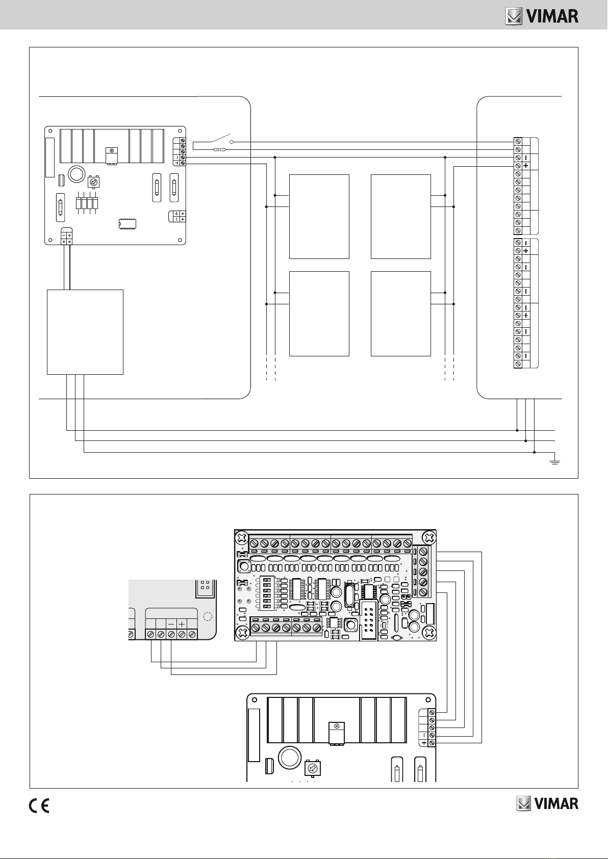
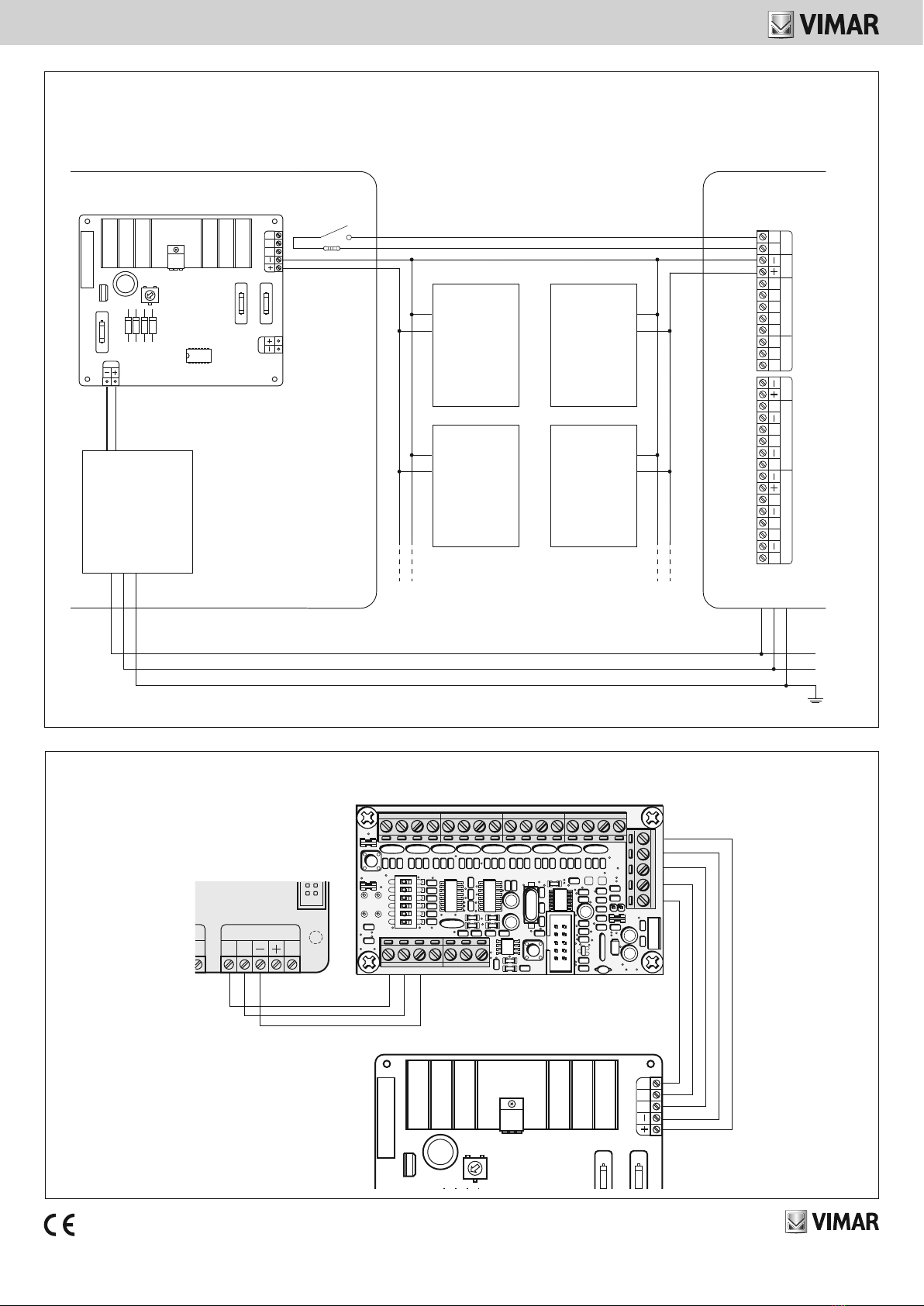
VISTA FRONTALE E SCHEDA
1.
2.
F3,15AF1 250V
BCTI
12V–
MC
F3,15AF2 250V
F3,15AF3 250V
18V–
D
A
B
A: Morsetti per collegamento trasformatore posizionato sotto la scheda elettronica.
B: Morsetti per collegamento batteria.
C: Morsetti + - per alimentazione dispositivi.
D: Morsetti per collegamento modulo espansione 8 ingressi 01704.
ATTENZIONE!
In caso di sostituzione, smaltire le batterie
negli appositi cassonetti per la raccolta differenziata.
C
RAEE - Informazione agli utilizzatori
Il simbolo del cassonetto barrato riportato sull’apparecchiatura o sulla
sua confezione indica che il prodotto alla fine della propria vita utile deve
essere raccolto separatamente dagli altri rifiuti. L’utente dovrà, pertanto,
conferire l’apparecchiatura giunta a fine vita agli idonei centri comunali di
raccolta differenziata dei rifiuti elettrotecnici ed elettronici. In alternativa
alla gestione autonoma è possibile consegnare l’apparecchiatura che si
desidera smaltire al rivenditore, al momento dell’acquisto di una nuova
apparecchiatura di tipo equivalente. Presso i rivenditori di prodotti elet-
tronici con superficie di vendita di almeno 400 m2è inoltre possibile con-
segnare gratuitamente, senza obbligo di acquisto, i prodotti elettronici da
smaltire con dimensioni inferiori a 25 cm. L’adeguata raccolta differenzia-
ta per l’avvio successivo dell’apparecchiatura dismessa al riciclaggio, al
trattamento e allo smaltimento ambientalmente compatibile contribuisce
ad evitare possibili effetti negativi sull’ambiente e sulla salute e favorisce
il reimpiego e/o riciclo dei materiali di cui è composta l’apparecchiatura.

Viale Vicenza, 14
36063 Marostica VI - Italy
www.vimar.com
49400895C0 01 1705
COLLEGAMENTO CON CENTRALE
TAMPER
+S
EXT +S
INT
12V
RELÈ 2ALLARME RELÈ 1
T T
NC NO C NC NO C
L6
L5
L4
L3
L2
L1L7L8
12V 12V
LINEE 1 - 4 LINEE 5 - 8
-
+
-
+
-
+
-
+
L
N
PE
F3,15AF1 250V
BCTI
12V–
MC
F3,15AF2 250V
F3,15AF3 250V
18V–
TRANFORMER 40VA IP20
3k3 Ω
01700-0170301717
DISPOSITIVI By-alarm
CN5
20
D
EA B
RS 485
BC MC TI
– +
M4
M5
M8
L1 L2 L3 L4 L5 L6 L7 L8
– – ––– + – +
B T TDEA
– +
123456
ON
F3,15AF1 250V
BCTI
12V–
MC
F3,15AF2
250V
F3,15AF3
250V
18V–
COLLEGAMENTO CON CENTRALE E MODULO ESPANSIONE 8 INGRESSI 01704
01700-01703
01704
01717
TAMPER

Viale Vicenza, 14
36063 Marostica VI - Italy
www.vimar.com
49400895C0 01 1705
By-alarm
01717-01717.120
FRONT VIEW AND BOARD
1.
2.
F3,15AF1 250V
BCTI
12V–
MC
F3,15AF2 250V
F3,15AF3 250V
18V–
D
A
B
C
By-alarm additional power supply unit 50/60 Hz 1.5 A, metal enclosure
with battery compartment, surface mounting.
TECHNICAL CHARACTERISTICS
•Power supply for art. 01717: 230 V~ (+10% / -15%) 50 Hz
•Power supply for art. 01717.120: 120 V~ (+10% / -10%) 60 Hz
• Stabilized voltage: 13.8 Vdc nominal (±2%)
•Rated current: 1.5 A total
• Ripple at 230 V~ -15%: 10 mV at maximum load
• Ripple at 120 V~ -10%: 350 mV at maximum load
•Autotest: dynamic and programmable
•Operating temperature: -10..+40 °C (indoor use)
•Dimensions: 345x435x125 mm
•Degree of safety 2 (EN 50131-6)
• Ambient class II (EN 50131-6)
BATTERIES
Sealed 12 V lead batteries must be used with flammability class UL94-HB; the cables
for connecting the battery are designed for Faston connectors.
For the screw connection, the Faston connector is to be cut and eyelet terminals
must be fixed to the ends of the cables.
CAUTION: Danger of explosion if the battery is replaced with one of the wrong
type.
OPERATING CURRENT
The operating current for the external loads depends on the characteristics of the
battery for self-powering the control panel according to the table alongside.
Current available with
internal battery of 7.2 Ah
Current available for
self-powering the system 1200 mA
Current for recharging battery 277 mA
Current available with
internal battery of 18 Ah
Current available for
self-powering the system 650 mA
Current for recharging battery 847 mA
INSTALLATION RULES
Installation should be carried out in compliance with the current regulations regarding
the installation of electrical equipment in the country where the products are installed.
Cable entry
The mains power supply cables must be inserted using the hole nearest to the 230
V~ connection terminal block and to which they must be fixed without having been
consolidated by soldering; they must also have been inserted in advance into an
additional sheath in order to ensure double insulation.
There must be an over-current circuit breaker with a high breaking capacity (1500 A)
upstream of the connection to the control panel.
If other holes are used for routing the cables, it is necessary to use cable outlets or
junction fittings for pipe or sheath constructed with materials of flammability class
HB or higher.
Earth connection
For the earth connection you need to use the specific terminal located near the trans-
former by the connection of its mains power supply; the metal cover should also be
earthed, using the Faston terminal.
Caution: correct earthing protects the control panel and all its devices from faults
caused by electrical and atmospheric discharges and in particular ensures the integ-
rity of the telecommunications network.
Fuses
F1: F 3.15A - 250V, located directly on the mains voltage terminals directly at the
input of the transformer, it protects the low alternating voltage input.
F2: T 3.15A - 250V, provides protection on the power supply positive output.
F3: T 3.15A - 250V, provides protection against polarity reversal of the battery.
REGULATORY COMPLIANCE
EN 50131-6.
LV directive. EMC directive.
Standards EN 60950-1, EN 50130-4, EN 61000-6-3.
WEEE - User information
The crossed bin symbol on the appliance or on its packaging indicates
that the product at the end of its life must be collected separately from
other waste. The user must therefore hand the equipment at the end of
its life cycle over to the appropriate municipal centres for the differen-
tiated collection of electrical and electronic waste. As an alternative to
independent management, you can deliver the equipment you want to
dispose of to the dealer when purchasing a new appliance of an equiva-
lent type. You can also deliver electronic products to be disposed of that
are smaller than 25 cm for free, with no obligation to purchase, to elec-
tronics retailers with a sales area of at least 400 m2. Proper sorted waste
collection for subsequent recycling, processing and environmentally
conscious disposal of the old equipment helps to prevent any possible
negative impact on the environment and human health while promoting
the practice of reusing and/or recycling materials used in manufacture.
A: Terminals for connecting the transformer located under the printed circuit board.
B: Terminals for connecting the battery.
C: Terminals + - for powering devices.
D: Terminals for connecting 8-input expansion module 01704.
WARNING:
Dispose of batteries in the specific
differentiated collection bins.

Viale Vicenza, 14
36063 Marostica VI - Italy
www.vimar.com
49400895C0 01 1705
CONNECTION TO THE CONTROL PANEL
TAMPER
+S
EXT +S
INT
12V
RELÈ 2ALLARME RELÈ 1
T T
NC NO C NC NO C
L6
L5
L4
L3
L2
L1L7L8
12V 12V
LINEE 1 - 4 LINEE 5 - 8
-
+
-
+
-
+
-
+
L
N
PE
F3,15AF1 250V
BCTI
12V–
MC
F3,15AF2 250V
F3,15AF3 250V
18V–
TRANFORMER 40VA IP20
3k3 Ω
TAMPER
CN5
20
D
EA B
RS 485
BC MC TI
– +
M4
M5
M8
L1 L2 L3 L4 L5 L6 L7 L8
– – ––– + – +
B T TDEA
– +
123456
ON
F3,15AF1 250V
BCTI
12V–
MC
F3,15AF2
250V
F3,15AF3
250V
18V–
CONNECTION TO THE CONTROL PANEL AND 8-INPUT EXPANSION MODULE 01704
01704
01717-01717.120
01700-01703
01700.120-01703.120
01717
01717.120
By-alarm DEVICES
01700-01703
01700.120-01703.120
This manual suits for next models
1
Table of contents
Languages:
Other Vimar Industrial Electrical manuals
Popular Industrial Electrical manuals by other brands

Murata
Murata GRT155R61A225ME01 Series Reference sheet

Murata
Murata GRM0335C1E330JA01 Series Reference sheet

Murata
Murata GRT21BC81C335KE13 Series Reference sheet

Murata
Murata GRM0225C1E5R2BA03 Series Reference sheet

Murata
Murata GRM1557U1A472JA01 Series Reference sheet

Murata
Murata GRM153D80J105ME95 Series Reference sheet

Murata
Murata GJM0225C1E6R4CB01 Series Reference sheet

Murata
Murata GQM22M5C2H5R6DB01 Series Reference sheet

Murata
Murata GRM0335C1H3R1BA01 Series Reference sheet

Murata
Murata GJM1555C1HR70BB01 Series Reference sheet

Murata
Murata GRM033R71C121KA01 Series Reference sheet

Murata
Murata GRM0335C1E8R9DA01 Series Reference sheet