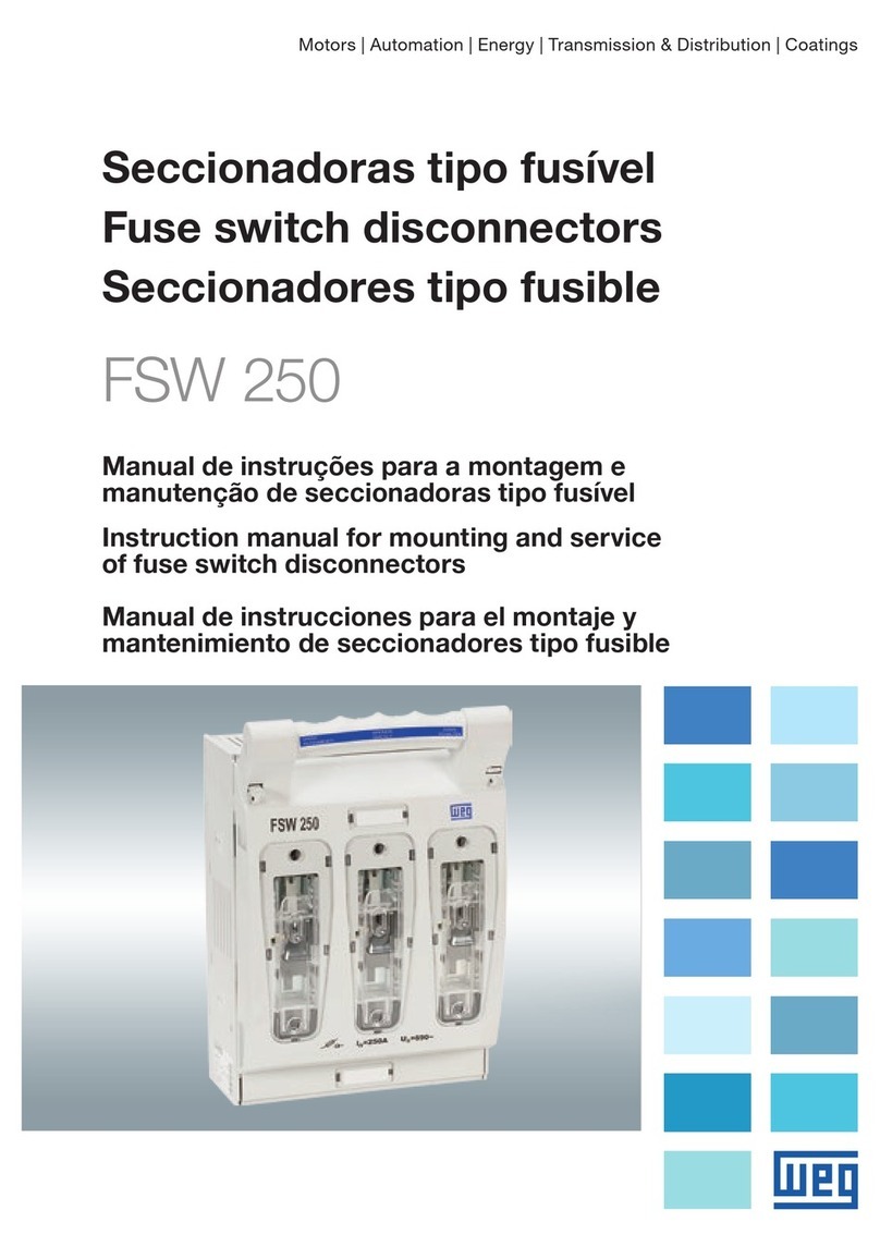
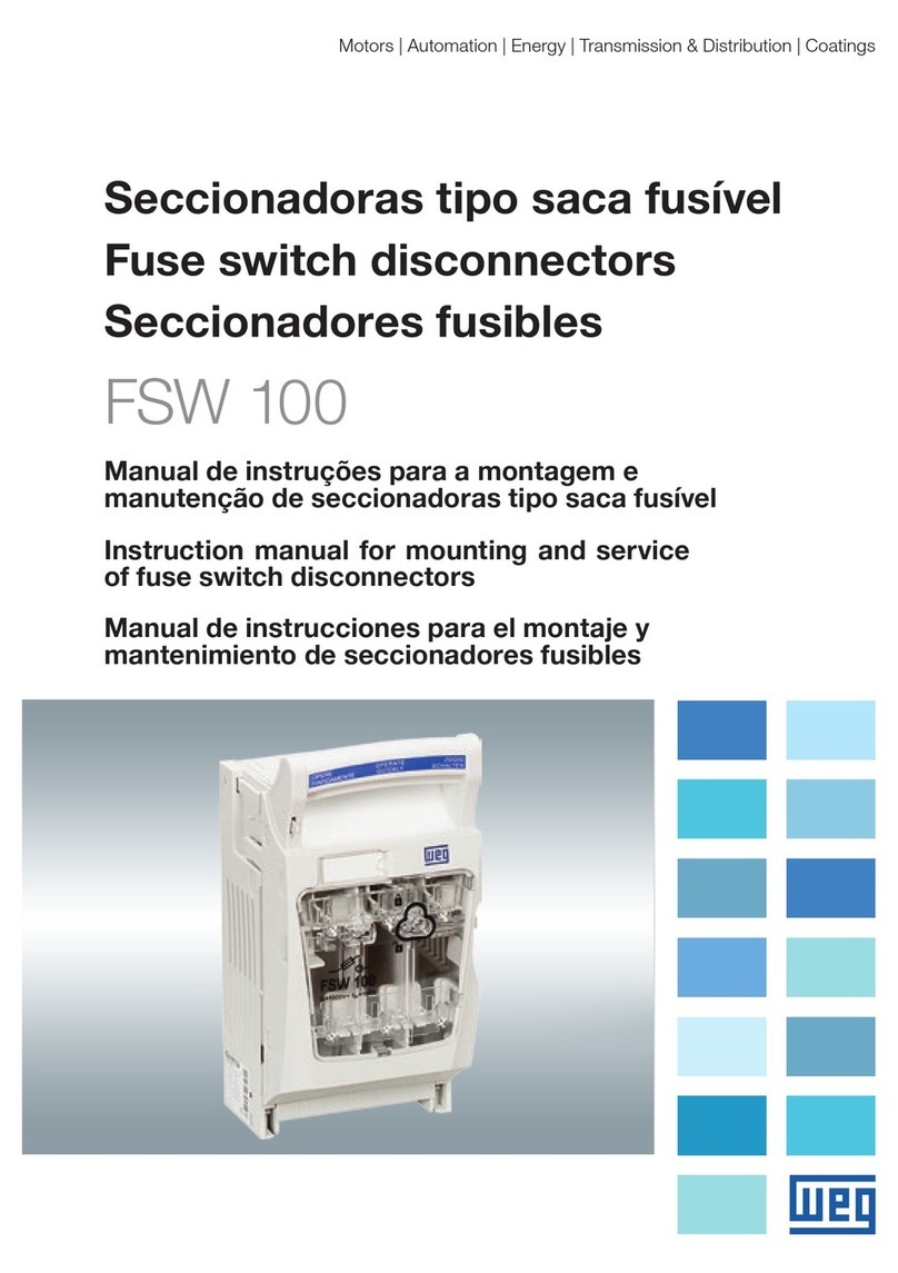
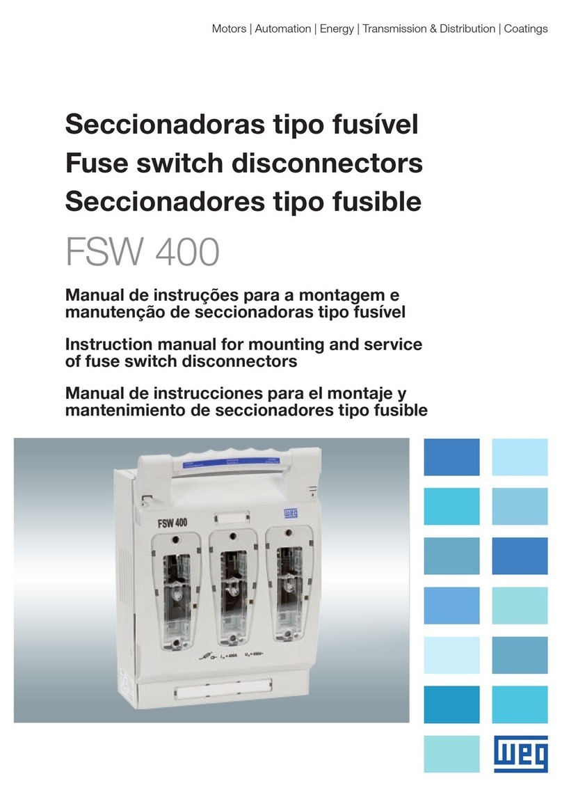
WEG FSW 630 User manual

Instruction manual for mounting and service
of fuse switch disconnectors
Motors | Automation | Energy | Transmission & Distribution | Coatings
Manual de instruções para a montagem e
manutenção de seccionadoras tipo fusível
Manual de instrucciones para montaje y
mantenimiento de seccionadoras fusibles
FSW 630
Seccionadoras tipo fusível
Fuse switch disconnectors
Seccionadores tipo fusible

www.weg.net
Manual de instruções para a montagem e manutenção de seccionadoras tipo fusível
2
17-23
Manual de instrucciones para el montaje y
mantenimiento de seccionadores tipo fusible
Español
3-9
Manual de instruções para a montagem e
manutenção de seccionadoras tipo fusível
Português
10-16
English
Instruction manual for mounting and
service of fuse switch disconnectors

www.weg.net
Manual de instruções para a montagem e manutenção de seccionadoras tipo fusível
3
CONTEÚDO
PORTUGUÊS
1. OPERAÇÕES BÁSICAS 4
1.1. ABERTURA DA TAMPA ...................................................................... 4
1.2. FECHAMENTO DA TAMPA................................................................ 4
1.3. RETIRADA DA TAMPA ....................................................................... 4
1.4. MONTAGEM DA TAMPA .................................................................... 5
1.5. RETIRADA DA PROTEÇÃO DE TERMINAIS .................................... 5
1.6. MONTAGEM DA PROTEÇÃO DE TERMINAIS ................................. 6
2.MONTAGEM DA SECCIONADORA 6
2.1. MONTAGEM DA SECCIONADORA NA BASE DE MONTAGEM ..... 6
3. FIXAÇÃO DOS CONDUTORES DE SAÍDA 7
3.1. FIXAÇÃO DOS CONDUTORES COM TERMINAL DE CABO -
GRAMPO PARAFUSO TIPO M ............................................................7
3.2. MONTAGEM DE CONDUTORES COM TERMINAL NU -
GRAMPO PONTE TIPO S ....................................................................7
4. INSERÇÃO, RETIRADA E VERIFICAÇÃO DAS CONDIÇÕES
DOS ELOS FUSÍVEIS 8
4.1. INSERÇÃO DOS ELOS FUSÍVEIS...................................................... 8
4.2. RETIRADA DOS ELOS FUSÍVEIS...................................................... 8
4.3. VERIFICAÇÃO DAS CONDIÇÕES DOS ELOS FUSÍVEIS................ 9
5. CONTATOS AUXILIARES..........................................................................9
6. DESCARTE DO MATERIAL UTILIZADO...................................................9
7. CONDIÇÕES DE TRANSPORTE E ARMAZENAMENTO..........................9

www.weg.net
Manual de instruções para a montagem e manutenção de seccionadoras tipo fusível
4
1. OPERAÇÕES BÁSICAS
1.1. ABERTURA DA TAMPA
Segure a alça e abra a tampa com firmeza (Figura 1).
Figura 2
Figura 1
1.2. FECHAMENTO DA TAMPA
Segure a alça e feche a tampa com firmeza (Figura 2).
1.3. RETIRADA DA TAMPA
Abra a tampa (de acordo com o ponto 1).
Mova a tampa ao longo da base da seccionadora e então retire a tampa (Figura 3).
Figura 3 Figura 4

www.weg.net
Manual de instruções para a montagem e manutenção de seccionadoras tipo fusível
5
1.4. MONTAGEM DA TAMPA
Insira a tampa na base da seccionadora e então mova a tampa ao longo da base da
seccionadora e feche com firmeza (4).
1.5. RETIRADA DA PROTEÇÃO DE TERMINAIS
Gire o parafuso 90 graus na proteção de terminais selecionada (Figura 5 e Figura 6).
Figura 5 Figura 6
Flexione ambos os grampos da proteção (Figura 7) e ao mesmo tempo remova a
proteção de terminais selecionada da base (Figura 8).
Figura 7 Figura 8

www.weg.net
Manual de instruções para a montagem e manutenção de seccionadoras tipo fusível
6
1.6. MONTAGEM DA PROTEÇÃO DE TERMINAIS
Mova a proteção de terminais até a base até que os grampos da tampa de terminais se
prendam (Figura 9).
Figura 9
2. MONTAGEM DA SECCIONADORA
2.1. MONTAGEM DA SECCIONADORA NA BASE DE MONTAGEM
Retire a tampa (de acordo com o item 3).
Retire as proteções de terminais (de acordo com item 5).
Fixe as seccionadoras com parafusos 4 x M8 (Figura 10) até que se tenha uma boa
fixação no painel.
Monte as proteções de terminais (de acordo com o item 6).
Monte a tampa (de acordo com o item 4).
Figura 10

www.weg.net
Manual de instruções para a montagem e manutenção de seccionadoras tipo fusível
7
3. FIXAÇÃO DOS CONDUTORES DE SAÍDA
3.1. FIXAÇÃO DOS CONDUTORES COM TERMINAL DE CABO - GRAMPO
PARAFUSO TIPO M
Retire a tampa (de acordo com o item 3).
Retire as proteções de terminais (de acordo com item 5).
Fixe os condutores com parafuso M12, com torque de 20 Nm (Figura 11).
Figura 11
O kit de parafusos é composto por 12 parafusos M8 e 6 grampos tipo S. Ficando a
critério do cliente a utilização de parafusos M12.
3.2. MONTAGEM DE CONDUTORES COM TERMINAL NU - GRAMPO
PONTE TIPO S
Retire a tampa (de acordo com o item 3).
Retire as proteções de terminais (de acordo com item 5).
Fixe os condutores com parafusos M8, 10 Nm (Figura 12).
Monte as proteções de terminais (de acordo com o item 6).
Monte a tampa (de acordo com o item 4).
Figura 12

www.weg.net
Manual de instruções para a montagem e manutenção de seccionadoras tipo fusível
8
4. INSERÇÃO, RETIRADA E VERIFICAÇÃO DAS CONDIÇÕES
DOS ELOS FUSÍVEIS
4.1. INSERÇÃO DOS ELOS FUSÍVEIS
Retire a tampa (de acordo com o item 3).
Coloque o elo fusível em um porta fusível (Figura 13), mova o elo fusível ao longo da
tampa até a trava de elos fusíveis prender.
Monte a tampa (de acordo com o ponto 4).
Figura 13
4.2. RETIRADA DOS ELOS FUSÍVEIS
Retire a tampa (de acordo com o item 3).
Mova o botão de liberação de travamento dos elos fusíveis (Figura 14) e em seguida
puxe e retire o elo fusível do porta fusível (Figura 15).
Figura 14 Figura 15

www.weg.net
Manual de instruções para a montagem e manutenção de seccionadoras tipo fusível
9
4.3. VERIFICAÇÃO DAS CONDIÇÕES DOS ELOS FUSÍVEIS
Verifique as condições dos elos fusíveis através do detector de tensão, por exemplo
(Figura 16).
Figura 16
5. CONTATOS AUXILIARES
A montagem da chave de contato auxiliar na seccionadora tipo fusível FSW 630
deve ser realizado pelo fabricante. Não é recomendada a montagem pelo usuário.
6. DESCARTE DO MATERIAL UTILIZADO
As seccionadoras fusíveis tipo FSW são fabricadas com o uso de materiais e
tecnologia que não são prejudiciais ao meio ambiente. Normas referentes à
proteção do meio ambiente devem ser respeitadas. O produto utilizado deve ser
desmontado e as peças metálicas devem ser separadas das peças plásticas.
Peças metálicas sem uso devem ser segregadas entre metais não ferrosos e
ferrosos e devem ser sucateadas. Peças plásticas que podem ser recicladas
devem ser enviadas para uma empresa de reciclagem. Peças plásticas que não
podem ser recicladas devem ser enviadas para uma empresa especializadas.
Embalagens de papelão e sacos plásticos recicláveis devem ser enviadas para
empresas de reciclagem. Em caso de dúvidas, entre em contato com o fabricante.
7. CONDIÇÕES DE TRANSPORTE E ARMAZENAMENTO
O armazenamento deve ser feito na embalagem original, em locais secos e limpos
com temperatura superior a -5 ºC e umidade relativa não superior a 80% com
temperatura de +35 ºC. Com a temperatura mais alta permitida de +40 ºC, a
umidade relativa do ar não deve ser superior a 50%.

www.weg.net
Instruction manual for mounting and service of fuse switch disconnectors
10
CONTENT
ENGLISH
1. BASIC OPERATIONS 11
1.1. OPENING THE COVER ......................................................................11
1.2. CLOSING THE COVER......................................................................11
1.3. TAKING OFF THE COVER.................................................................11
1.4. MOUNTING THE COVER ................................................................. 12
1.5. TAKING OFF THE SHIELD FOR TERMINALS ................................ 12
1.6. MOUNTING OFF THE SHIELD FOR TERMINALS.......................... 13
2.MOUNTING THE DISCONNECTOR 13
2.1. MOUNTING THE DISCONNECTOR ON THE MOUNTING PLATE.... 13
3. FIXING OUTGOING CONDUCTORS 14
3.1. FIXING CONDUCTORS WITH CABLE TERMINAL -
M TYPE BOLT CLAMP .......................................................................14
3.2. MOUNTING OF CONDUCTORS WITH BARE TERMINAL -
S TYPE BRIDGE CLAMP...................................................................14
4. INSERTING, TAKING OUT AND CHECKING THE CONDITIONS
OF THE FUSE LINKS 15
4.1. INSERTING OF THE FUSE LINKS ................................................... 15
4.2. TAKING OUT THE FUSE LINKS ...................................................... 15
4.3. CHECKING THE CONDITIONS OF THE FUSE LINKS................... 16
5. AUXILIARY CONTACT BLOCK...............................................................16
6. PROCEEDING WITH THE MATERIAL UTILIZED...................................16
7. TRANSPORT AND STORAGE CONDITIONS......................................... 16

www.weg.net
Instruction manual for mounting and service of fuse switch disconnectors
11
1. BASIC OPERATIONS
1.1. OPENING THE COVER
Take the handle and open the cover up to firm resistance (Picture 1).
Picture 1 Picture 2
1.2. CLOSING THE COVER
Take the handle and close the cover up to confirm resistance (Picture 2).
1.3. TAKING OFF THE COVER
Open the cover (acc. to point 1).
Move the cover along the base of the disconnector and then take off the cover (Picture 3).
Picture 3 Picture 4

www.weg.net
Instruction manual for mounting and service of fuse switch disconnectors
12
1.4. MOUNTING THE COVER
Insert the cover into the base of disconnector and then move the cover along the base
of disconnector up to firm resistance (Picture 4).
1.5. TAKING OFF THE SHIELD FOR TERMINALS
Turn the screw by 90 degrees in the selected shield of terminals (Picture 5 and Picture 6).
Picture 5 Picture 6
Deflect both of the fasteners of the shield (Picture 7) and at the same time withdraw
selected shield for terminals from the base (Picture 8).
Picture 7 Picture 8

www.weg.net
Instruction manual for mounting and service of fuse switch disconnectors
13
1.6. MOUNTING OFF THE SHIELD FOR TERMINALS
Withdraw the shield for terminals up to the base until the fasteners of the cover for
terminals are fasten (Picture 9).
Picture 9
Turn the screw by 90 degrees in the selected shield of terminals in the reverse direction
than in point 5.a.
2. MOUNTING THE DISCONNECTOR
2.1. MOUNTING THE DISCONNECTOR ON THE MOUNTING PLATE
Take off the cover (acc. to point 3).
Take off the shields for terminals (acc. to point 5).
Fix the disconnector with bolts 4 x M8 (Picture 10).
Mount the shields for terminals (acc. to point 6).
Mount the cover (acc. to point 4).
Picture 10

www.weg.net
Instruction manual for mounting and service of fuse switch disconnectors
14
3. FIXING OUTGOING CONDUCTORS
3.1. FIXING CONDUCTORS WITH CABLE TERMINAL - M TYPE BOLT
CLAMP
Take off the cover (acc. to point 3).
Take off the shields for terminals (acc. to point 5).
Fix the conductor with M12 screw and torque 20 Nm (figure 11).
The screw kit is compound by 12 M5 screw and 6 clips type S.
Picture 11
The screw kit is compound by 12 M8 screw and 6 clips type S. Getting the customer’s
discretion to use the M12 screw.
3.2. MOUNTING OF CONDUCTORS WITH BARE TERMINAL - S TYPE
BRIDGE CLAMP
Take off the cover (acc. to point 3).
Take off the shields for terminals (acc. to point 5).
Fix the conductors with (M8 bolts, 10 Nm) (Picture 12).
Mount the shields for terminals (acc. to point 6).
Mount the cover (acc. to point 4).
Picture 12

www.weg.net
Instruction manual for mounting and service of fuse switch disconnectors
15
4. INSERTING, TAKING OUT AND CHECKING THE CONDI-
TIONS OF THE FUSE LINKS
4.1. INSERTING OF THE FUSE LINKS
Take off the cover (acc. to point 3).
Place the fuse link in a fuse holder (Picture 13), move a fuse link along the cover until the
locking for fuse links is fasten.
Mount the cover (acc. to point 4).
Picture 13
4.2. TAKING OUT THE FUSE LINKS
Take off the cover (acc. to point 3).
Move the release button for locking of fuse links (Picture 14) and then withdraw and
take out the fuse link from the fuse holder (Picture 15).
Picture 14 Picture 15

www.weg.net
Instruction manual for mounting and service of fuse switch disconnectors
16
4.3. CHECKING THE CONDITIONS OF THE FUSE LINKS
Make checking the conditions of the fuse links for example by voltage detector (Picture 16).
Picture 16
5. AUXILIARY CONTACT BLOCK
The assembly of auxiliary contact block in the fuse switch-disconnectors FSW 630
it will be assembled manufacturers.
6. PROCEEDING WITH THE MATERIAL UTILIZED
FSW type fuse switch disconnectors are manufactured with the use of materials
and technology which are not harmful to the natural environment. Obligatory
regulations regarding protection of the environment should be respected. The
product utilized should be dismantled and metal parts should be apart from plastic
ones. Useless metal parts should be segregated to non- ferrous metals and others
and they are to be scraped. Plastic parts which can be recycled should be sent
to recycling company. Plastic parts which can not be recycled should be sent to
utilization company. Cardboard packaging and plastic bags which are recycled
should be sent to recycling companies. In case of any doubts please contact with
the manufacturer.
7. TRANSPORT AND STORAGE CONDITIONS
Storage should be performed in original packaging, in dry and clean rooms at
temperature higher than - 5 ºC and related humidity not higher than 80% at
temperature + 35 ºC. At the highest temperature +40 ºC air humidity should not
be higher than 50%.

www.weg.net
Manual de instrucciones para montaje y mantenimiento de seccionadoras fusibles
17
CONTENIDO
ESPAÑOL
1. OPERACIONES BÁSICAS 18
1.1. APERTURA DE LA TAPA.................................................................. 18
1.2. CIERRE DE LA TAPA........................................................................ 18
1.3. RETIRADA DE LA TAPA................................................................... 18
1.4. MONTAJE DE LA TAPA.................................................................... 19
1.5. RETIRADA DE LA PROTECCIÓN DE TERMINALES..................... 19
1.6. MONTAJE DE LA PROTECCIÓN DE TERMINALES...................... 20
2.MONTAJE DE LA SECCIONADORA 20
2.1. MONTAJE DE LA SECCIONADORA EN LA BASE DE MONTAJE.... 20
3. FIJACIÓN DE LOS CONDUCTORES DE SALIDA 21
3.1. FIJACIÓN DE LOS CONDUCTORES CON TERMINAL DE CABLE -
GRAPA TORNILLO TIPO M................................................................21
3.2. MONTAJE DE CONDUCTORES CON TERMINAL DESNUDO -
GRAPA PUENTE TIPO S....................................................................21
4. INSERCIÓN, RETIRADA Y VERIFICACIÓN DE LAS
CONDICIONES DE LOS ESLABONES FUSIBLES 22
4.1. INSERCIÓN DE LOS ESLABONES FUSIBLES............................... 22
4.2. RETIRADA DE LOS ESLABONES FUSIBLES ................................ 22
4.3. VERIFICACIÓN DE LAS CONDICIONES DE LOS
ESLABONES FUSIBLES.................................................................. 23
5. BLOQUE DE CONTACTO AUXILIAR.......................................................23
6. DESCARTE DEL MATERIAL UTILIZADO...............................................23
7. CONDICIONES DE TRANSPORTE Y ALMACENAMIENTO...................23

www.weg.net
Manual de instrucciones para montaje y mantenimiento de seccionadoras fusibles
18
1. OPERACIONES BÁSICAS
1.1. APERTURA DE LA TAPA
Sujete el alza y abra la tapa con firmeza (Figura 1).
Figura 1 Figura 2
1.2. CIERRE DE LA TAPA
Sujete el alza y cierre la tapa con firmeza (Figura 2).
1.3. RETIRADA DE LA TAPA
Abra la tapa (de acuerdo con el punto 1).
Mueva la tapa a lo largo de la base de la seccionadora y a continuación retírela (Figura 3).
Figura 3 Figura 4

www.weg.net
Manual de instrucciones para montaje y mantenimiento de seccionadoras fusibles
19
1.4. MONTAJE DE LA TAPA
Inserte la tapa en la base de la seccionadora y muévala a lo largo de la base de la sec-
cionadora, cerrándola con firmeza (4).
1.5. RETIRADA DE LA PROTECCIÓN DE TERMINALES
Gire el tornillo 90 grados en la protección de terminales seleccionada (Figura 5 y Figura 6).
Figura 5 Figura 6
Flexione ambas trabas de la protección (Figura 7) y al mismo tiempo remueva la protec-
ción de terminales seleccionada de la base (Figura 8).
Figura 7 Figura 8

www.weg.net
Manual de instrucciones para montaje y mantenimiento de seccionadoras fusibles
20
1.6. MONTAJE DE LA PROTECCIÓN DE TERMINALES
Mueva la protección de terminales hasta la base, hasta que las trabas de la tapa de
terminales queden sujetas (Figura 9).
Figura 9
Gire el tornillo 90 grados en la protección de terminales seleccionada, en la dirección
opuesta al ítem 5.a.
2. MONTAJE DE LA SECCIONADORA
2.1. MONTAJE DE LA SECCIONADORA EN LA BASE DE MONTAJE
Retire la tapa (de acuerdo con el ítem 3).
Retire las protecciones de terminales (de acuerdo con el ítem 5).
Fije las seccionadoras con tornillos 4 x M8 (Figura 10).
Monte las protecciones de terminales (de acuerdo con el ítem 6).
Monte la tapa (de acuerdo con el ítem 4).
Figura 10
Table of contents
Languages:
Other WEG Industrial Electrical manuals