Vimco LUTRON Sivoia SV-MDU-HT-W-R Manual

Page 1
shading solutions byVIMCOTM
1System Dimension Overview pg. 3
2Fastening Mounting Brackets pg. 4
3Attaching MDU pg. 5
4Hanging the Shade pg. 5,6
5Wiring MDU pg. 7,8
6Setting Up MDU pg. 9,10
7Shade Controls pg. 11
8MDU w/ SV-IR Module pg. 12
9Troubleshooting pg. 13
10 Part Specs pg. 14
Contents
Infrared Handheld
Transmitter
Idler
Support
Bracket
Fabric & Roller Assembly
Motor Drive Unit (MDU)
MDU Bracket
Wallstation Controls
SV-IR Infrared Receiver
Module
A Typical Sivoia Motorized Shade System
(Wallstation Controls, SV-IR Infrared Receiver Module, and Infrared Handheld Transmitter not included with this kit)
IMPORTANT NOTES!
• These instructions apply to a right-mounted system configuration. For left-mounted
configurations, all diagrams are inverted.
• High torque installations require the use of a Sivoia®High Torque Motor Drive Unit (MDU).
Standard Sivoia MDUs should not be used in high torque installations. High torque MDUs
will be shipped with labels identifying them as such.
Installation & Operating Instructions
SV-MDU-HT-W-R High Torque Roller
SV-MDU-HT-W-L Installation Kit
Motorized Shade Systems
®

Page 2
shading solutions byVIMCOTM
CARTON CONTENTS
Motor Drive Unit (MDU)
(exploded view - ships assembled)
SV-IR Module Connecting
Wire (SV-IR Infrared
Receiver Module sold
separately)
Sivoia High
Torque Axle
MDU & Idler Support Mounting Brackets
(right mount equipment shown)
1/2 in. (13 mm) Idler
and MDU Truss-head
Screws (x8)
2 1/2 in. (64 mm) Hex-Head
Self-Drilling Screws (x12)
• #2 Phillips Screwdriver
• 3/8 in. (9.5 mm) Socket Driver
• 1/8 in. (3.2 mm) Straight Blade Screwdriver
• Power Drill: Drill Bits, Screwdriver Attachments
• Level
• Pliers
• Tape Measure
• Wire Cutter
• Wire Stripper
TOOLS REQUIRED

Page 3
shading solutions byVIMCOTM
SYSTEM DIMENSIONS OVERVIEW
Use the following diagrams in conjunction with the Sivoia®Order Invoice to accurately position the mounting brackets.
Notes: 1. Only mount system where ambient temperature will be 32˚F - 122˚F (0˚C - 50˚C).
2. Depending on the height of the shade, tube width can be up to 1/4 in. (6.4 mm) wider than the specified
Fabric Width (FW).
3. Measure Tube Length (see diagram below) and use this dimension when installing mounting brackets.
Bracket to Bracket (B to B) Width
[Tube Length + 4 1/4”(108 mm)]
Tube Length
2 3/4”
(70 mm)
8 1/2”
(220 mm)
1 1/2”
(38 mm)
Figure 1: Standard Mounting Bracket Application
Bracket Indentions as
reference for Tube Edges
1

Page 4
shading solutions byVIMCOTM
FASTENING MOUNTING BRACKETS
A. Position the indentions on each bracket (see diagram below) at the desired fabric location. These indentions
designate where the tube edges should lie once the shade roller is in place. Use a level to ensure both brackets are
at the same height and parallel to the window casing.
Note: Fasten the top of the brackets 8 1/2 in. (220 mm) from the top of the window trim to ensure complete
window exposure when the shades are in full open position.
B. Fasten the brackets to studs in the wall using no less than six(6) hex-head self-drilling screws.
Note: All six (6) screws must be securely fastened to a stud or other structural member.
CAUTION! Sivoia®High Torque Roller Shades can weigh up to 225 lbs. (102 kg), depending on the size and
fabric type. Make sure the mounting brackets are fastened to structural elements rated to support such loads.
Before AND after the mounting brackets have been fastened to the wall, confirm the Tube Length
dimension (see pg. 3). Make any necessary bracket position adjustments based on this assessment.
Bracket Indentions as guides
for Tube Edges
Bracket Indentions as reference
for Tube Edges
Wall Mount
Ceiling Mount
Ceiling Mount
Wall Mount
8 1/2”
(22 cm)
Tube Length
2

Page 5
shading solutions byVIMCOTM
ATTACHING MDU TO MOUNTING BRACKET
B. Attach the MDU to the mounting bracket using three
(3) truss-head screws.
HANGING THE SHADE
A. Unwrap approximately 6 in. (150 mm) of material.
B. Attach the shade to the MDU first by engaging the roller’s hexagonal socket with the motor’s hexagonal drive ball. You
may need to rotate the roller in order to push the shade over the hexagonal drive ball.
C. Insert the idler pin into the slot of the idler support and drop it into place. Make sure the idler support is fully open.
C
B
Idler Support Mounting
Bracket
Idler Pin
CAUTION! Sivoia®High Torque Roller Shades can weigh up to 225 lbs. (102 kg), depending on the size and
fabric type. For safety purposes, make sure at least two (2) individuals/installers are present when hanging
the shade.
3
4

Page 6
shading solutions byVIMCOTM
HANGING THE SHADE (CONTINUED)
D. Once the idler pin is in place, tighten the shade retaining/leveling screw to keep the idler pin secure (“locked”).
Adjust the leveling of the shade roller by further tightening or loosening the shade retaining/leveling screw.
Note: The idler support is considered to be in the “locked”position when the idler pin cannot be removed from the
idler support slot (see diagram below).
Idler Support
“Locked”
Shade Retaining/
Leveling Screw
CAUTION! Not setting the shade
retaining/leveling screw into the "locked" position
prior to operating the shade can result in damage
to the system.
Idler Pin in Idler
Support Slot
CAUTION! Make sure the Idler Support
remains “locked”after adjusting the leveling
of the shade roller.
Idler Support
“Locked”
4

Page 7
shading solutions byVIMCOTM
A
C
1234 567 8
Cntrl 1
Cntrl 2
Ground
AC
AC
Drain
MUX
MUX
B
Do not connect if there is only one MDU in the system. If
there are multiple MDU's in the system,the MDU's must be wired
together. Connect the MUX, Drain, and MUX terminals of each MDU
together in a daisy chain or homerun configuration.
To a Sivoia®wall mounted keypad, or a Sivoia®interface such
as the SV-CCI or the SV-GRXI. The CNTRL1 and CNTRL2 wires
are polarity sensitive.
WIRING MDU - SINGLE MOTOR
Connecting Wires to the MDU Terminal Block
The terminal block located at the bottom of the MDU is the wire
connection point for: power, communication, keypads, and interfaces.
A. Remove terminal block cover (if not yet removed) by pressing in
on the cover and then pulling downward.
B. Grasp terminal block and pull down to separate from connecting
block.
C. Connect wires to the terminal block according to the diagram
below.
D. Replace the terminal block and the terminal block cover.
Wire to a Sivoia®plug-in transformer, junction box mount
transformer, or a Sivoia®power panel. Each MDU must be EARTH
grounded. One Sivoia®transformer can power ONLY ONE MDU
regardless of shade size.
Wire Type
Control
Description
2 conductors / #22-24 AWG
3 conductors (2 shielded, 1 drain) / #24 AWG
Belden®wire model #1883A
3 conductors #22 AWG
Lutron model # SV-IR-EXT-10
3 conductors:
2 / #18-22 AWG (24 VAC power supply)
1 / #18-22 AWG (earth ground)
6 conductors:
2 / #16 AWG (24 VAC power supply)
1 / #18 AWG (earth ground)
3 #22 AWG shielded + 1 #24 AWG drain (comm link)
(Lutron wire model no. SV-CBL-MDU-250)
Control to MDU: 250’(76 m)
Max. Length
4000’. (1333 m) per system
1000’(333 m) from MDU to MDU
50’. (15 m) per system - total of 5
SV-IR-EXT-10, 10’(3 m) each
MDU to Sivoia®power panel:
200’(61 m)
Transformer to MDU:
#18 AWG - 150’(46 m)
#20 AWG - 100’(31 m)
#22 AWG - 60’(18 m)
A
Comm Link B
Comm & Power
( & combined)
D
Power Wires C
SV-IR Extension
Cable E
C
A
B
Control
Comm
Link
Power
Supply
B
5

B
C
Com
MUX
MUX
1234567 8
Cntrl 1
Cntrl 2
Ground
AC
AC
Com
MUX
MUX
A
C
1234 5678
Cntrl 1
Cntrl 2
Ground
AC
AC
Com
MUX
MUX
AC
G
N
D
B B
A
AC
Page 8
shading solutions byVIMCOTM
WIRING MDU - WIRING MULTIPLE MOTORS TOGETHER
Wire to a Sivoia®plug-in transformer, junction box mount
transformer, or a Sivoia®power panel. Each MDU must be
EARTH grounded. One Sivoia®transformer can power
ONLY ONE MDU regardless of shade size.
To a Sivoia®wall
mounted keypad, or
a Sivoia®interface
To a Sivoia®wall
mounted keypad, or
a Sivoia®interface
A maximum of 64 MDU's can be wired
together per system
MDU Terminal Blocks
Control
Comm Link
Comm Link
Power
Supply
Control
Next
MDU
Next
MDU
Comm Link
Power Supply
Wire Type
Control
Description
2 conductors / #22-24 AWG
3 conductors (2 shielded, 1 drain) / #24 AWG
Belden®wire model #1883A
3 conductors #22 AWG
Lutron model # SV-IR-EXT-10
3 conductors:
2 / #18-22 AWG (24 VAC power supply)
1 / #18-22 AWG (earth ground)
6 conductors:
2 / #16 AWG (24 VAC power supply)
1 / #18 AWG (earth ground)
3 #22 AWG shielded + 1 #24 AWG drain (comm link)
(Lutron wire model no. SV-CBL-MDU-250)
Control to MDU: 250’(76 m)
Max. Length
4000’(1333 m) per system
1000’(333 m) from MDU to MDU
50’(15 m) per system - total of 5
SV-IR-EXT-10, 10’(3 m) each
MDU to Sivoia®power panel:
200’(61 m)
Transformer to MDU:
#18 AWG - 150’(46 m)
#20 AWG - 100’(31 m)
#22 AWG - 60’(18 m)
A
Comm Link B
Comm & Power
( & combined)
D
Power Wires C
SV-IR Extension
Cable E
C
B
5

Page 9
shading solutions byVIMCOTM
SETTING UP MOTOR DRIVE UNIT (MDU) - SINGLE MDU
6
The Motor Drive Unit (MDU) should come from the factory with limits set. In order to change the factory limits, follow
the steps below. If there is only one MDU in the system, open and close limits are the only steps required. Follow the
programming steps outlined in the programming table below. If the system has multiple MDUs, follow the single MDU
setup directions for each MDU and then continue with the setup codes for multiple MDU systems on the next page.
Press the Set button to save the
corrent position as the “Close
Limit.”The display will read
and blink for 4 seconds, then go
blank.
SET
OPEN
CLOSE
MODE
Open Limit: The position the shade moves to when it opens.
Close Limit: The position the shade moves to when it closes.
Programming Table
STEPS MODE
Open Limit:
Press the Mode
button on the MDU
until the display
reads
Close Limit:
Press the Mode
button on the MDU
until the display
reads
STEP 2
Use the Open and Close buttons on the
MDU to adjust the shade to the open
position desired.
Use the Open and Close buttons on the
MDU to adjust the shade to the closed
position desired.
Press the Set button to save the
corrent position as the “Open
Limit.”The display will read
and blink for 4 seconds, then go
blank.
ADJUST SET
Mode Button
Open and Close
Buttons
Set Button
Display on bottom of MDU
STEP 1

Page 10
shading solutions byVIMCOTM
All MDU’s with the same room
address and the
same address
Multiple MDU Set-Up Codes
SETTING UP MOTOR DRIVE UNIT (MDU) - MULTIPLE MDU's
Control Station: Determines which MDU's in the system will respond to a "Group" keypad or "Group" interface control
that is wired to the MDU being setup. It is not necessary to change the control station setting of an MDU that does not have
any keypads or interfaces wired to it.
Room Address: The room address groups MDU's on the communication link. A group is defined as all MDU's with the
same room address number. There are 32 room addresses available in a single system, therefore, a system can have up to
32 groups. Typically, all MDU's in a room will be set to the same room address. Use the room address to help determine
how keypads will control the MDU's in the system. Refer to the control station setting table below for information on how
the room address setting affects how the system is controlled by keypads or interfaces.
Scene Lockout: Turns off the ability to set or adjust PRESET stop points. To activate, set the scene lockout setting to 1.
To deactivate, set the scene lockout setting to 0. Changing this setting on any MDU will change all the MDU's in the
system. Scene lockout setting can be deactivated from any MDU in the system.
Link Address: Each MDU must be set to a unique Link Address number to allow the MDU's to communicate on the
communication link. There are 64 link addresses available, meaning the maximum number of MDU's in a single system is
64.
Any keypad or interface CANNOT be wired to more
than one MDU.
Group keypads/interfaces and individual
keypads/interfaces can be wired to the same MDU.
A maximum of 9 keypads/interfaces can be wired
to one MDU.
There are two types of Sivoia®keypads and
interfaces, group and individual types. The table
to the left describes how a group type controls a
system depending on the CS setting of the MDU it
is wired to. An individual type only controls the
MDU it is wired to, regardless of the CS setting of
the MDU it is wired to.
SPECIAL NOTES:
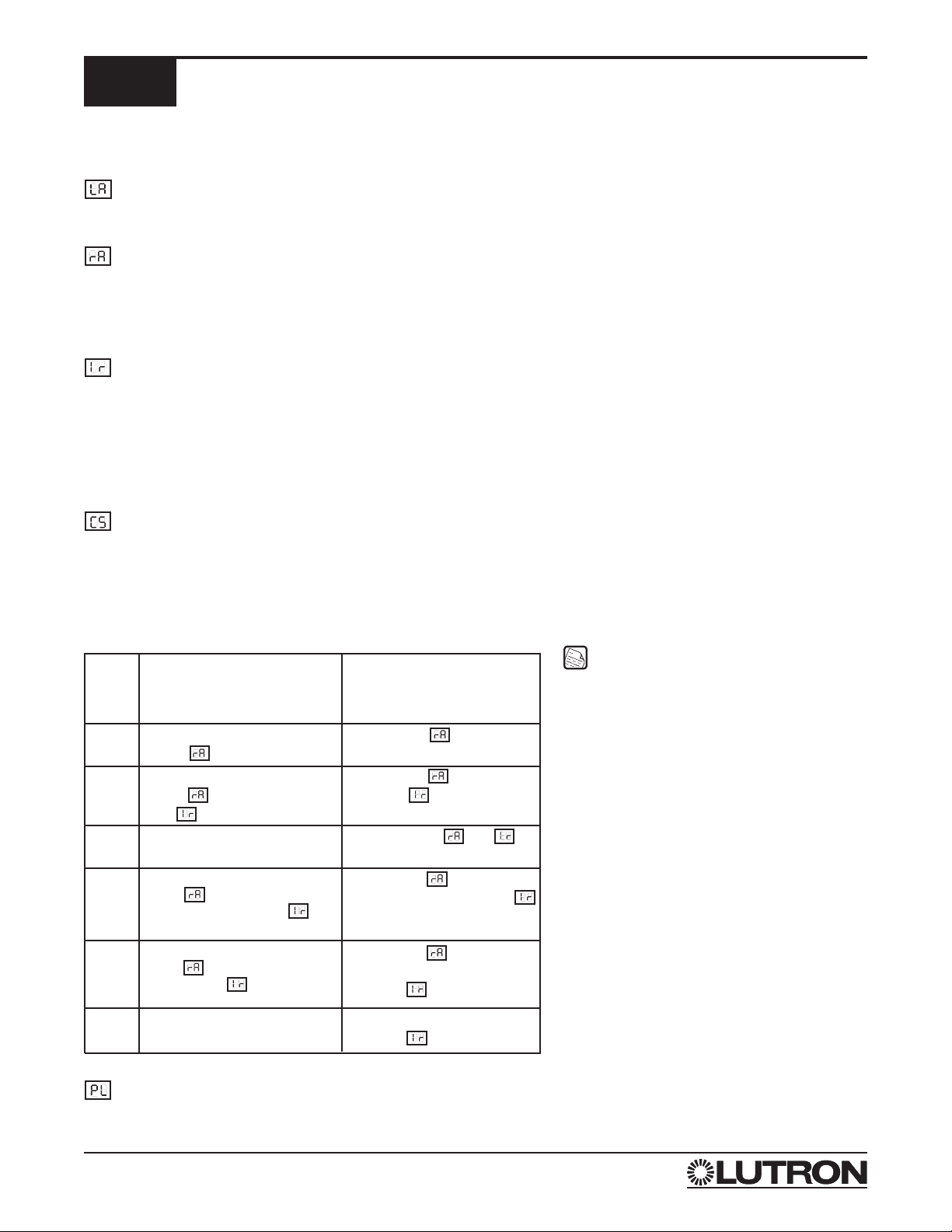
Control Station Setting Table
MDU
CS
Setting
0
1
2
Which MDU’s in a System Will
Respond
All MDU’s with the same room
address
All MDU’s in the system
All MDU’s with the same room
address and the same Front (F)
or Rear (r) assignment in the
address
4
3
5
All MDU’s with the same room
address and the same number (1,
2, 3, or 4) in the address setting
All Front MDU’s or all Rear MDU’s
in the system
What MDU Address Settings
Determine which MDU in the
System Will Respond
Room address
Room address
IR address
Not dependent on and
address settings
Room address
Front or Rear in the IR address
Room address
Same number (1, 2, 3, or 4) in the
IR address
Front or Rear in the
IR address
IR Address: Used to set the IR address a MDU will respond to. Some IR hand controls have the ability to control
subgroups of shades within a group, as defined by the room address described above. There are 16 subgroups available.
Each IR address (subgroup) is made up of two parts, the IR address number (1, 2, 3, 4, 5, 6, 7 or 8) and its shade location
(F or r), the FRONT shade or the REAR shade. Any number of MDU's can have the same IR address. The IR address can
also be used to determine subgroups of the MDU's when a keypad or interface is used to control the system. Refer to the
control station setting table below for information on how the IR address affects how the system is controlled by keypads or
interfaces.
6

Page 11
shading solutions byVIMCOTM
SHADE CONTROLS
7
LUTRON
Surface Mount Group Wall Keypad - SV-1PG-WH
Note: Pressing any button while shade is moving will stop the shade.
SETTING PRESET:
1.) Use the Raise and Lower buttons until shade is at the level you wish to store as the "PRESET".
2.) Press and hold the Preset button (approximately 4 seconds) until appears in the MDU's LED display.
OPEN
PRESET
CLOSE
PRESS ONCE:
Shade goes to open
limit
PRESS ONCE:
Shade goes to close
limit
PRESS:
To close shade
PRESS:
To open shade
PRESS ONCE:
Shade goes to preset
level
Front View Rear View
MDU Pin 1
CNTRL 1
MDU Pin 2
CNTRL 2
PRESS:
To close shade
PRESS ONCE:
Shade goes to open
limit
PRESS ONCE:
Shade goes to close
limit
PRESS:
To open shade
Note: Pressing any button while shade is moving will stop the shade.
Split Button Open/Close Infrared Handheld Transmitter - SV-OCIT

Page 12
shading solutions byVIMCOTM
MDU WITH SV-IR INFRARED RECEIVER MODULE
Sivoia®system covered by
decorative valence
The SV-IR allows the MDU to be controlled directly with a Sivoia®Infrared Handheld Transmitter (SV-OCIT, SV-3PIT,
SV-4S2G-IT, or SV-4GD-OCIT). The SV-IR receiver connects to the MDU via a 20 in. (51 cm) cable. This provides the
SV-IR receiver ample mounting range to offset most infrared signal restrictions caused by a protective/decorative
covering for the shade system. To extend the IR receiver mounting range, add up to five (5) SV-IR-EXT-10 extension
cables (10 ft. [3 m] each).
Note: To control an individual shade with an IR transmitter, the SV-IR must be connected to that MDU. If there is a
Group/Subgroup of MDU’s with the same Room/IR Address (see page 11),the SV-IR need only be connected to
one of those MDU’s to control the entire Group/Subgroup.
- The SV-IR receiver must be located to allow line-of-sight reception of infrared signals.
- The SV-IR has a range of 30 ft. (9 m) when receiving infrared signals.
- The SV-IR must NOT be located near lighting fixtures or in direct sunlight.
- The SV-IR must be located within 50 ft. (15 m) of the MDU it is connected to. Add up to five (5) SV-IR-EXT-10
extension cables (10 ft. [3 m] each).
MDU
SV-IR Infrared Receiver Module
8

Page 13
shading solutions byVIMCOTM
TROUBLESHOOTING
9
PROBLEM SOLUTION
The shade will not go up or down. 1. Check power to the motor unit by pressing the MODE
button. If the LED display does not show anything check
that:
•transformer is plugged into a live outlet.
•power wiring is not shorted.
•power wiring terminal is not miswired or
disconnected.
2. If the LED display shows something, try to open and close
the shade using the buttons marked open and close on the
motor drive unit. If the shade does not respond, the shade
material or weight bar may be binding on the roller frame or
end brackets. Check for and clear all obstructions.
The shade does not respond to control. 1. Check that power is connected to the shade.
2. Check that the wall keypad has been wired correctly.
3. Check that the control terminal block is connected securely
and in the proper order.
4. Check batteries if using IR remote.
The shade does not roll straight. (Fabric veers or telescopes) 1. If the shade veers or telescopes toward the right, correct by
lowering shade completely and place a piece of tape as
close to the left edge of the roller as possible. If shade
veers or telescopes towards the left, tape must be placed as
close to the right edge of the roller as possible. Note
multiple pieces may be necessary.

Page 14
shading solutions byVIMCOTM
PART SPECS
7.95”
(202 mm)
7.95”
(202 mm)
5.4”
(137 mm)
5”
(127 mm)
3.4”
(87 mm)
4.25”
(108 mm)
MDU Mounting Bracket
Idler Mounting Bracket
MDU Dimensions
Side View “A”Side View “B”
Front View
Front View
Side View
Front ViewSide View
Back View
3.25”
(82 mm)
2.40”
(61 mm)
4”
(102 mm)
6.75”
(17.1 cm)
10

Page 15
shading solutions byVIMCOTM
Notes

shading solutions byVIMCOTM
Lutron Electronics Co., Inc.
Made and printed in U.S.A.
P/N 045-008 Rev. C 3/03
LIMITED WARRANTY
SIVOIA®MOTORIZED WINDOW SHADE SYSTEM EIGHT YEAR LIMITED WARRANTY
Vimco warrants, for eight years from shipment, each new SIVOIA Motorized Window Shade System to be free from defects in materials or workmanship under
conditions of normal use and specified ambient temperature when installed and operated in accordance with Vimco product specifications, applicable local
electrical and building codes, applicable National Electrical Code®provisions, and the Safety Standards of Underwriter's Laboratories.
What Vimco Will Do
Upon the return of a system or system component, subsequently determined by Vimco to be defective, Vimco will, in its sole discretion, repair or replace the
defective system or system component, provided that Vimco was promptly notified of the alleged defect within the warranty period, and provided that the
system or system component was properly installed, wired, insulated, used, and maintained, as determined solely by Vimco. Vimco shall not be required to
remove, install, or re-install any system or system component alleged to be defective.
Vimco will issue a credit for the cost of the repair or the replacement in accordance with the following schedule:
For the first 2 years after the date of shipment 100%
For years 3, 4, and 5 after the date of shipment 50%
For years 6, 7, and 8 after the date of shipment 25%
What This Warranty Does Not Cover
1. Damage or improper operation determined by Vimco to be due to normal wear and tear, or to abuse, misuse, or accident, such as:
a. Use of incorrect line voltages;
b. Use of incorrect fuses or circuit breakers;
c. Failure to follow operating instructions provided by Vimco;
d. Unauthorized repairs or adjustments or alterations;
e. Direct exposure to corrosive materials;
f. Vandalism;
g. Fire, flood, “Acts of God”, and other factors beyond the control of Vimco.
2. The cost of labor, including any labor required to remove, install, or re-program any replacement item.
3. Components and equipment external to the SIVOIA Motorized Window Shade System, such as:
a. Non-Lutron lighting and automation systems;
b. Building wiring; and
c. Other manufacturers’equipment, including, but not limited to:
i. Time clocks;
ii. Audio-visual equipment; and
iii. Photo sensors.
4. The cost of repairing or replacing property or equipment other than the warranted system.
How to Get Service under This Warranty
Should you experience the need for service under this warranty, please contact your SIVOIA Motorized Window Shade System service representative
immediately; or
Contact Vimco by telephone toll-free at:
1-800-446-1503; or
By mail to: VIMCO Shading Systems
11520 Sun Shade Lane
Ashland, VA 23005
or;
LIMITATIONS AND EXCLUSIONS
THIS WARRANTY IS EXCLUSIVE. THERE ARE NO OTHER EXPRESS WARRANTIES.
THE IMPLIED WARRANTY OF MERCHANTABILITY IS LIMITED TO TWO YEARS FROM THE DATE OF SHIPMENT. VIMCO SHALL NOT BE LIABLE FOR
ANY REPAIR WORK UNDERTAKEN WITHOUT ITS PROPER WRITTEN CONSENT, OR FOR INCIDENTAL, CONSEQUENTIAL, OR SPECIAL DAMAGES.
VIMCO’S LIABILITY ON ANY CLAIM FOR DAMAGES ARISING OUT OF OR IN CONNECTION WITH THE MANUFACTURE, SALE, INSTALLATION,
DELIVERY, USE, REPAIR, OR REPLACEMENT OF THE SHADING SYSTEM SHALL NEVER EXCEED THE PRICE PAID FOR THE SYSTEM. SOME
STATES DO NOT ALLOW LIMITATIONS ON HOW LONG AN IMPLIED WARRANTY LASTS, SO THE ABOVE LIMITATION MAY NOT APPLY TO YOU.
SOME STATES DO NOT ALLOW THE EXCLUSION OR LIMITATION OF INCIDENTAL OR CONSEQUENTIAL DAMAGES, SO THE ABOVE LIMITATION OR
EXCLUSION MAY NOT APPLY TO YOU.
This product may be covered under one or more of the following U.S. Patents: 5,467,266; 5,671,387; 5,848,634; 6,100,659; 6,201,364; 6,313,588; 6,346,781 DES.
317,593; DES. 344,068; DES. 370,663; DES. 378,814; DES. 387,736 DES. 391,924; DES. 396,448; DES. 437,585; and DES 450,043; and corresponding foreign
patents. U.S. and foreign patents pending. Lutron, Sivoia, and the Sunburst logo are registered trademarks of Lutron Electronics Co., Inc. VIMCO and shading solutions
by VIMCO are trademarks of Virginia Iron & Metal Company, Inc. National Electrical Code is a registered trademark of the National Fire Protection Association, Quincy,
Massachusetts.
© 2003 Virginia Iron & Metal Company, Inc.
Internet: www.vimco.com, www.lutron.com
This manual suits for next models
1
Other Vimco Indoor Furnishing manuals
Popular Indoor Furnishing manuals by other brands

Lifetime
Lifetime ADIRONDACK 60335 Assembly instructions

Forte
Forte SRBL1184B Assembling Instruction

Seconique
Seconique MATLOCK DINING TABLE Assembly instructions

Lightolier
Lightolier Lighting Systems LSBW-11 Specification sheet

Lucid
Lucid Headboard Assembly instructions

pelipal
pelipal 9030-HS45-01 manual

PAIDI
PAIDI 125 5011 instructions

rvs alvema
rvs alvema 700 ABC manual

Article
Article LENIA Assembly instructions

Furniture of America
Furniture of America CM3212HB Assembly instructions

Grohe
Grohe Electronic 15180XX1 installation instructions

CABINETS TO GO
CABINETS TO GO Findley & Myers OC3384 Assembly instructions