Vingtor Stentofon VPA-120 Supplement

INSTALLATION & SERVICE MANUAL
VPA PUBLIC ADDRESS AMPLIFIERS
VPA-120 / 240 / 400
A100K10876

Page 2 Installation and Service Manual A100K10876
VPA Amplifiers
Table of Contents
1INTRODUCTION................................................................................ 3
1.1 About this document................................................................... 3
1.2 Equipment covered by this document ........................................ 3
1.3 Rules and regulations................................................................. 3
1.4 Publication log ............................................................................ 3
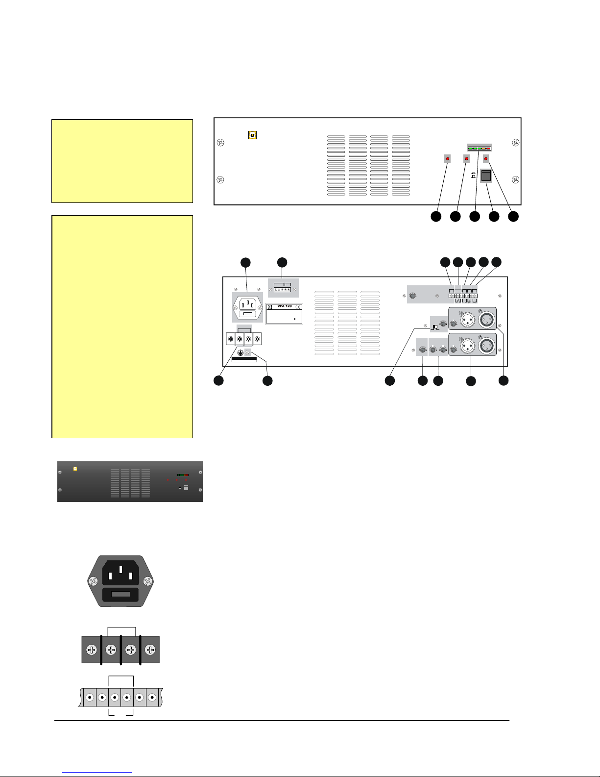
2CONNECTORS AND CONTROLS ................................................... 4
2.1 Front and rear panels ................................................................. 4
2.2 Cabinet ....................................................................................... 4
2.3 Power ......................................................................................... 4
2.4 Signal inputs ............................................................................... 5
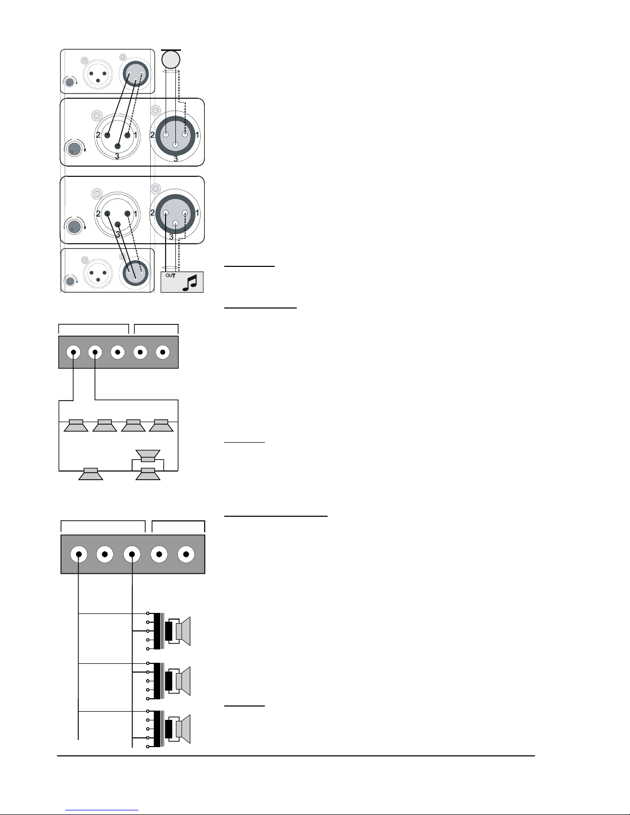
2.5 Loudspeaker outputs.................................................................. 5
2.6 Optional connections.................................................................. 5
2.7 Indicators .................................................................................... 5
3INSTALLATION................................................................................. 6
3.1 Unpacking................................................................................... 6
3.2 Mounting..................................................................................... 6
3.3 Wiring ......................................................................................... 6
3.3.1 Cable requirement, marine installations ............................. 6
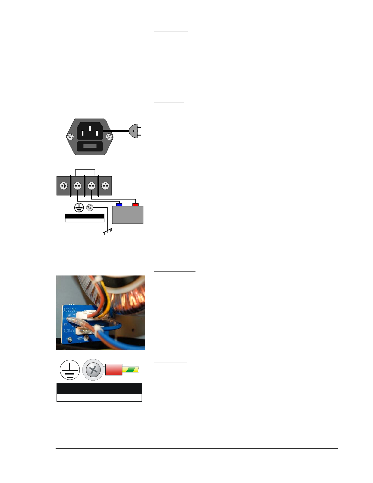
3.3.2 Mains power ....................................................................... 7
3.3.3 Grounding ........................................................................... 7
3.3.4 Input connection ................................................................. 8
3.3.5 Loudspeaker connection..................................................... 8
3.3.6 Optional connections .......................................................... 9
4STARTUP AND OPERATION......................................................... 10
4.1 System check-out ..................................................................... 10
4.1.1 Preparations ..................................................................... 10
4.1.2 Sound................................................................................ 10
4.1.3 Speaker line fault detection .............................................. 11
5SERVICE ......................................................................................... 12
5.1 Service information................................................................... 12
5.2 Troubleshooting........................................................................ 12
5.3 Fuse replacement..................................................................... 13
5.3.1 Mains and low voltage protection ..................................... 13
5.3.2 24 V out protection............................................................ 13
5.3.3 Mains transformer protection ............................................ 13
5.4 Technical data .......................................................................... 14
6APENDIX ......................................................................................... 15
6.1 Block diagram........................................................................... 15
6.2 Schematic diagram, Amplifier................................................... 16
6.3 Schematic diagram, Booster .................................................... 17
6.4 Component numbers, Amplifier................................................ 18
6.5 Component values, Amplifier ................................................... 19
6.6 Component numbers, Booster ................................................. 20
6.7 Component values, Booster ..................................................... 21

A100K10876 Installation and Service Manual Page 3
VPA Amplifiers
1 INTRODUCTION
1.1 About this document
This manual is intended to give relevant information on the system
features, available equipment, typical configurations, simplified wiring
and programming and technical data for the concept.
In addition this document will contain schematic diagrams and other
relevant documentation for service and maintenance which are not
included in the User and Installation Manual 16 911 007.
This document is aimed at
zService personnel
zInstallers
1.2 Equipment covered by this document
Public Address amplifiers
zVPA-120 120 W
zVPA-240 240 W
zVPA-400 400 W1
NOTE! The amplifiers are delivered for 230 VAC as standard.
For 115 VAC mains, a plug must be moved and fuses must be
changed. See section 3.3.4.
1.3 Rules and regulations
The VPA system and its components have been tested according to the
following regulations:
zEN 60065: 2002
“Audio, video and similar electronic apparatus. Safety requirements”
zIEC 60533: Second edition, 1999
"Electrical and electronic installation in ships - Electromagnetic
compatibility".
zEN 60945: Fourth edition, 2002
"Maritime navigation and radio communication equipment and
systems - General requirements - Methods of testing and required
test results".
zIACS E10: Corr.1 July 2003
"Unified environmental test specifications - Testing procedure for
electric control and monitoring, safety and protection, onboard
computer based systems and peripherals, loading instruments,
internal communication and other electrical equipment as considered
appropriate".
1.4 Publication log
v.1.0 Sep. 2007
A100K10876 Nov. 2010
1VPA-400 is not available per October 2007.
Please contact Your VINGTOR/STEENHANS supplier for delivery details.

Page 4 Installation and Service Manual A100K10876
VPA Amplifiers
2 CONNECTORS AND CONTROLS
The connectors and controls of all three amplifier types are identical
except for the maximum rated output power.
2.1 Front and rear panels
2
VPA-120
POWER AMPLIFIER
ON
OFF
POWER
FAULT
OVERLOAD
-18 -10 -6 0 +1dB
1 3 4 5
OUT
OUT
CALL
–
6 + 6
–
6 + 6
0
000
CHIME
CHIME
ON OFF
IN
IN
0
MONITOR
TONE
MASTER BASS TREBLE BGM
0– +– +
COM
800 mA
8Ω
NC
NO
_
COM
24V
+
DC IN
– 24V +
LINE FUSE: 10A 250V
AC 230V ~
Rated output power: 120W
Supply voltage: ~ 60Hz/50Hz
Power consumption: AC 350VA
24V 140W
Serial No:_______ _____ Made in Chi na
115V/230V
Power Amplifier
Warning
This apparatus must be earthed
COM
8Ω
100V
COM
100V
67
89
11 12 14
15 16 17 18 19
13
10
MONITOR FAULTRELAY DC OUT REMOTE PRIORITY
CALL/BMG CALL ONLY
115V / 230V select is internal
2.2 Cabinet
The amplifier is prepared for mounting in a standard 19” rack and will
occupy 3HU (133 mm) in height.
The amplifier can also be free-standing on a level, open surface.
Each amplifier has a built-in cooling fan, the front and back must be kept
free of objects in order to secure sufficient air flow.
2.3 Power
The amplifiers are powered from 230 or 115 VAC mains, or 24 VDC.
The mains voltage is set inside the amplifier (default setting is 230 V).
There is a mains circuit breaker on the cabinet front, and a mains fuse in
conjunction with the mains inlet. The fuse value depends on the
amplifier type.
24 VDC can be used as a backup source in case of mains power failure.
The 24 V backup is not turned off by the mains switch or interrupted in
case of a blown mains fuse.
If an accumulator is used as 24 V backup, it will not be charged from the
amplifier.
24 VDC/800 mA is available from the amplifier for external equipment.
1 – Overload warning
2 – Fault warning
3 – VU-meter, -18, -10, -6, 0, +1dB
4 – Mains switch
5 –Power-on lamp
6 – 24 VDC backup power
7 – Frame ground connection
8 – Mains power connector and fuse
9 – Loudspeaker connections
10 – Pre-warning chime signal control
11 – Master volume control
12 – Master tone controls
13 – Entertainment input and output
with volume preset
14 – Call/alarm audio input and output
with volume preset
15 – 8 ohm monitor loudspeaker
output with volume control
16 – no/nc relay for amplifier fault
warning
17 – 24 VDC 800 mA power to
external equipment
18 – Remote volume control
19 – Priority over entertainment input
VPA-120
POWER AMPLIFIER
ON
OFF
POWER
FAULTOVERLOAD
-18 -10 -6 0 +1dB
LINE FUSE: 230V 2.5A
115V 5A
DC IN
- 24V +
DC OUT
800 mA
-
24V
+

A100K10876 Installation and Service Manual Page 5
VPA Amplifiers
The amplifier must be grounded either through the earth leg in the
mains plug or by a 1.5 mm wire between the amplifier’s ground terminal
and proven good grounding point, e.g. the rack frame.
2.4 Signal inputs
There are two inputs with 3-pin XLR connectors.
zEntertainment (BGM) for background music etc. with separate
preset input level control.
zCall / alarm input for announcements and alarm messages with
separate preset input level control.
Both inputs are connected in parallel with signal outputs to slave
amplifiers or recorders.
There are common master tone- and volume controls for both inputs. In
addition, the volume may be controlled remotely by an external
potentiometer.
A call input signal will automatically mute the BGM entertainment source
(VOX function). This can also be achieved manually by connecting the
microphone switch to the priority terminals.
A pre-warning chime signal can be given in front of a message when a
priority switch is pushed. This feature can be switched on/off and the
chime loudness can be adjusted.
2.5 Loudspeaker outputs
There are three loudspeaker outputs:
zCall and Background Music (BMG), full power output available on
an 8 Ohm terminal as well as on a 100 V constant voltage line.
zCall only, full power output on a 100 V constant voltage line. This
terminal carries no background music.
zMonitor Loudspeaker, 1 W power output to an 8 Ohm loudspeaker,
normally mounted close to the amplifier to monitor entertainment and
call channels. The output has a separate volume control.
2.6 Optional connections
zFault Relay, NO/NC contacts of a built-in relay is available for
remote warning devices. The relay is activated during fault conditions
such as mains power failure or open or shorted speaker lines.
zDC Out, 24 VDC/800 mA is available for optional equipment.
zRemote, connection of remote master volume control. A logaritmic
22 kOhm potmeter is suitable.
zPriority, by pushing a button on the microphone, a chime signal is
manually activated in front of a message.
2.7 Indicators
zPower on, red LED is lit when the amplifier is powered from mains
or battery.
zVU-meter, row of five LEDs indicating the signal pressure from -18
dB to +1 dB.
zFault, a red warning LED will be lit if the master volume is set to less
than 40%, or if the loudspeaker line is shorted.
A fault relay will be activated during fault conditions; the switch-over
contacts are available on the rear for remote warning devices.
zOverload, a red warning LED will be lit if the input signal is too high,
or if the loudspeaker impedance is too low (too many loudspeakers
in parallel) or shorted loudspeaker line.
OUT
OUT
CALL
BGM
– 6 + 6
– 6 + 6
0
0
IN
IN
00
MASTER BASS TREBLE
0– +– +
CHIME
CHIME
ON OFF
0
CALL / BMG CALL ONLY
COM
8Ω
100V
COM
100V
MONITOR
COM
8Ω
MONITOR
M
O
NIT
O
R FAULT RELAY D
C
O
UT REM
O
TE PRI
O
RITY
COM
800 mA
8
Ω
NC
NO
-
COM
24V
+
POWER
FAULT
OVERLOAD
-
18
-
10
-
6
0
+
1
dB
Warning
This appatatus must be earthed
PRI
O
RITY

Page 6 Installation and Service Manual A100K10876
VPA Amplifiers
3 INSTALLATION
3.1 Unpacking
The amplifier was thoroughly checked at the factory. Inspect the
amplifier, the enclosed parts and the shipping container for signs of
improper handling during shipment. If you find any damage, immediately
contact the dealer from whom you purchased the unit to make a claim.
3.2 Mounting
The amplifier should be installed in a technical room with adequate
ventilation, a recommended temperature between 18-25OC, less than
95% RH and an AC power outlet with provision for grounding.
The VPA rack is compass safe at a distance of >325 cm and the VPA
panel needs 95 cm to be compass safe.
The amplifier is prepared for mounting in a rack with a standard width of
483 mm (19”), and 133 mm (3 HU - 5 ¼”) vertical space.
The rack must provide sufficient ventilation. A 1 HU ventilation grid
above the amplifier is recommended if more than one amplifier are
mounted.
When VPA units are delivered ready mounted in a 19” rack like SPA
and VPA systems, the 1HU grid is included.
WARNING:
Failure to observe the above precautions could result in
overheating that could damage the equipment or create a fire
hazard.
See also the data sheet for each amplifier.
3.3 Wiring
3.3.1 Cable requirement, marine installations
All electrical wiring external to the equipment shall be approved ship-
cable of type 0.75 mm2 twisted pair with outer braided copper screen.
The cable should at least be a flame-retardant type to cover the
requirement in SOLAS Ch. II-1/45.5.2.
Where cables for service are required to be operable under fire
conditions, they must be a fire resistant type complying with the
requirements of IEC 60331. That is where the cables pass through
machinery spaces of category A and other high fire risk areas other than
those which they serve.
For passenger vessels this requirement also applies for cables passing
through main vertical fire zones (IACS UR E15).
zExamples of high fire risk areas are, apart from machinery space of
category A:
-Galleys and pantries containing cooking appliances
-Laundry with drying equipment
-Spaces defined by §§ (8), (12) and (14) of SOLAS Ch.II-2 Reg.
9.2.2.3.2.
-Areas with fuel handling equipment
zThe following electrical services are required to be operable under
fire conditions:
-Fire and general alarm system
-Public address system

A100K10876 Installation and Service Manual Page 7
VPA Amplifiers
Cable layout
zDo not run the installation cable from microphone and alarm panels
parallel to, or to near the cables for loudspeakers or power cables.
zThe screens must be interconnected in junction boxes and grounded
in the VPA main unit only. It is good practice to have separate
conducts for each type of signal cabling.
zTwo-conductor shielded cable is required for the microphone.
3.3.2 Mains power
WARNING:
Do not connect AC power to the amplifier until all the necessary
input and output connections have been completed.
The customer must provide a dedicated single phase power input which
should adhere to the following recommendations:
z230 VAC, 50-60 Hz, fused and capable of delivering a maximum of
2 A per 100 Watt amplifier power.
z24 VDC emergency power (if required), fused and capable of
delivering a maximum of 8 A per 100 Watt amplifier power.
zThe operating power should be wired and fused independently from
all other inputs.
zThe power must not be controlled by a mains switch.
zA warning tag should be attached to circuit-breaker-type fuses to
prevent unauthorized manual operation.
zThe mains power cable must be 3 x 2.5 mm2 rated for 500 VAC.
zThe 24 VDC power cable dimension has to be calculated depending
on the total low voltage power consumption and cable length.
zProper grounding is essential for reliable operation.
Note! The VPA unit has to be connected to the vessel’s central
ground.
115 VAC mains
zBe sure the amplifier is set for the correct mains voltage. Default
setting is 230 VAC.
zIf there is 115 VAC in the mains outlet, a plug must be moved inside
the cabinet.
-Open the cabinet by removing the screws on both sides and
remove the top cover.
-Locate the power board close to the mains transformer and move
the plug on CN3 (230V) to CN6 (115V).
zChange the fuse values according to the table in section 5.3.
3.3.3 Grounding
WARNING:
Do not disconnect the third (yellow/green) wire in the power plug.
This wire grounds the amplifier’s chassis to prevent a possible
shock hazard.
If an adapter is used to connect the plug to an ungrounded outlet,
make sure that the amplifier’s chassis is connected to the vessel’s
central ground.
In a rack installation, the amplifier’s grounding point is connected to the
rack frame.
Warning
This appatatus must be earthed
LINE FUSE: 230V 2.5A
115V 5A
DC IN
- 24V +
Warning
This appatatus must be earthed
MAINS
24 V
+

Page 8 Installation and Service Manual A100K10876
VPA Amplifiers
3.3.4 Input connection
The CALL and BMG line inputs are balanced, accepting 0.5 -1.5 Vrms
signal over 47 Kohm. The input level is adjustable +/- 6 dB.
zThe signal source is connected between pin 2 and 3, the wire screen
is connected to pin 1. Pin 2 is the “warm” side.
zConnect the entertainment source to the BGM input.
zConnect the dynamic microphone to the CALL input.
If the signal source is unbalanced, connect the signal wire to pin 2, and
the neutral to pin 3.
zIf two or more amplifiers are used in parallel, connect the OUT
terminals on the main amplifier to the corresponding IN terminals on
the slave amplifier.
The input levels must be adjusted individually.
3.3.5 Loudspeaker connection
WARNING:
Installation and service shall be performed by qualified personnel
only. Disconnect power supply before servicing.
Low impedance
The 8 Ohm low impedance CALLl/BGM output is used when the wires
to the speakers are relatively short and the line loss is less than 0.5 dB.
Most audio- and sound-system handbooks have tables listing the line
loss for different wire sizes and loads.
Use serial and/or parallel speaker arrangements as needed to obtain
proper impedance and power matching.
For best performance, select a coarse wire size and make sure the total
loudspeaker impedance adds up to 8 Ohm.
It is important to select speakers capable of handling the actual power.
Example:
Output power = 120 W, 6 speakers of 15 W, 1 speaker of 30 W.
Loop A = 4 x 4 Ohm = 16 Ohm 120 W / 2 = 60 W
Loop B = 8 Ohm + 16//16 Ohm = 16 Ohm 120 W / 2 = 60 W
Loop A//B = 16//16 Ohm = 8 Ohm
Constant voltage lines
The 100 V connectors for CALL/BGM and CALL ONLY should be used
when a large number of speakers are installed and/or the speakers are
placed far from the amplifier. Speakers with a line-matching transformer
designed for constant voltage lines must be used.
The speakers must be connected in parallel. The impedance taps on the
primary of the line transformers decide the power taken from the line.
One or more speakers may be removed or added without disturbing the
rest of the system.
Speakers are added as needed until the total wattage absorbed by the
line transformers is equal to the rated output power of the amplifier. It is
good practice to give power headroom of 10-20%. i.e. a speaker load of
100 W on a 120 W amplifier.
Note that the total load is calculated from the load on CALL/BGM +
CALL ONLY.
Example:
Calculate the max number of 6 W speakers on a 240 W amplifier.
Number of speakers = Amplifier power/Speaker power = 240/6 = 40.
OUT
OUT
OUT
OUT
CALL
CALL
BGM
BGM
– 6 + 6
– 6 + 6
– 6 + 6
– 6 + 6
0
0
0
0
IN
IN
IN
IN
SLAVE
SLAVE
C
ALL
/
BM
G
C
ALL
O
NLY
COM
8Ω
100V
COM
100V
8Ω16Ω
= 16Ω
= 16Ω
16Ω
4Ω4Ω4Ω4Ω
15W
30
W
= 8 /120W
Ω
= 60W
= 60W
1
5
W
15W
15W 15W 15W
Loop A
Loop B
CALL / BMG CALL ONL
Y
COM
8Ω
100V
COM
100V
6W
3W
9W
0
0
0
3
3
3
6
6
6
9
9
9
12
12
12

A100K10876 Installation and Service Manual Page 9
VPA Amplifiers
3.3.6 Optional connections
Monitor loudspeaker
Mount an 8 ohm loudspeaker rated at minimum 1.5 W close to the
amplifier to monitor entertainment and call channels.
Connect the loudspeaker wires to the MONITOR terminals marked
COM and 8Ω.
Adjust the volume to a desired value with the pot. next to the terminal.
Fault relay
Connect one wire from an external warning device to the FAULT RELAY
terminal marked COM.
Insert a suitable power supply between the other device wire and the
NO terminal.
The power on the DC OUT terminals may be used if the warning device
works on 24 VDC and consumes less than 800 mA.
The relay contacts can switch up to 7 A at 230 VAC or 30 VDC.
DC out
Optional equipment related to the PA amplifier may be powered from
the DC OUT terminals if the device works on 24 VDC and consumes
less than 800 mA. This output is protected by a 1 A thermistor.
Note the polarity if the device is polarity dependant.
Remote volume control
Mount an optional 22 kOhm log potentiometer in a convenient place in
order to adjust the master PA volume.
Use a shielded cable to connect the volume control to the REMOTE
terminals. The center tap on the pot is connected to the rightmost
terminal and the shield connects the cold pot tap to the left terminal.
Priority
A push-button, normally on the announcement microphone, is
connected to the PRIORITY terminals to establish a chime signal in
front of a call. The CHIME switch must be ON.
MONITOR FAULT RELAY DC OUT REMOTE PRIORITY
COM
800 mA
8
Ω
8 Ohm
1 W
NC
NO
-
COM
24V
+
MONITOR
MONITOR DC OUT REMOTE PRIORITYFAULT RELA
Y
COM
800 mA
8
Ω
NC
NO
-
COM
24V
+
Ext.
Power
MONITOR REMOTE PRIORITYFAULT RELAY DC OUT
COM
800 mA
8
Ω
NC
NO
-
COM
24V
+
Ext. Device
+
_
MONITOR DC OUT PRIORITYFAULT RELAY REMOTE
COM
800 mA
8
Ω
NC
NO
-
COM
24V
+
22 kOhm
M
O
NIT
O
R D
C
O
UT REM
O
TEFAULT RELAY PRI
O
RIT
Y
COM
800 mA
8
Ω
NC
NO
-
COM
24V
+
Mic

Page 10 Installation and Service Manual A100K10876
VPA Amplifiers
4 STARTUP AND OPERATION
4.1 System check-out
4.1.1 Preparations
zBe sure all connections are properly made according to chapter 3.
zTurn all volume controls to min. position (CCW).
zConnect the power cord to the mains outlet.
zTurn the mains switch ON and check that the POWER LED is on.
The FAULT and OVERLOAD LEDs should not be lit.
zNone of the VU-meter LEDs should be lit. The first green LED (-18
dB) may be glowing.
4.1.2 Sound
A signal source should be connected to the BGM input and a
microphone to the CALL input.
Background music check
zTurn the signal source on and set the BGM level pot. to mid position.
zIf a remote volume control is connected, set it to max. position.
zAdjust the master volume to an agreeable level.
zCheck that all loudspeakers connected to the CALL/BGM output are
sounding without distortion. Loudspeakers connected to the CALL
ONLY output should be silent.
zThe VU-meter should indicate up to the yellow field (0 dB).
zIf a remote volume control is connected, turn it CCW to check it
function. Turn it fully CW before proceeding.
zIf a monitor speaker is mounted, turn its volume control CW to check
the sound in the monitor.
Call check
The PA amplifier has an automatic VOX control which means that if a
signal on the CALL input exceeds ca. 300 mV, the signal on BGM will
be muted. If the signal is less, the call signal will be mixed with BGM.
zSet the CALL level pot. to mid position.
zActivate the microphone by pressing its button. The BGM should be
muted and the spoken message should be clearly reproduced in all
loudspeakers.
zIf the CHIME feature is implemented, set the CHIME switch to ON
and the CHIME volume to mid pos.
A “Ding-Dong” signal should be heard before the message.
zWith the mic button still depressed, stop talking. The background
music should softly return after 3-4 sec.
This delay may be adjusted with a pot on the lower left board (AMP-
1) inside the amplifier.
zRelease the mic. switch.
zAdjust the BGM, CALL, CHIME and MASTER volume controls as
well as BASS and TREBLE to optimal sound and balance.
zIf a remote volume control is connected, the MASTER volume should
be turned to max., and the remote volume control should be used to
set the correct level.
VOX delay

A100K10876 Installation and Service Manual Page 11
VPA Amplifiers
4.1.3 Speaker line fault detection
A 23 kHz tone is continuously transmitted on the loudspeaker line to
detect faulty lines. The switch on the upper left board (AMP-2) inside the
cabinet should be ON to enable this function.
If the FAULT LED on the front is on without any obvious reasons, or the
first VU-meter LED is lit without any signal source, the pilot tone level
may need adjustment.
zSet all volume controls to their final levels.
zTurn the power OFF and remove the cabinet cover.
zReconnect the power and locate the trimming pot on the AMP-2
board.
No external signal must be applied to the amplifier.
zTurn the pot CW until the first green LED (-18 dB) is lit.
Observe that the FAULT LED is off.
zTurn the pot slowly back CCW until the LED just extinguishes.
Observe that the FAULT LED is off.
The pilot tone level should now be correct.
zTurn the power off and remount the cabinet cover.
Pilot tone on/off
Fault level

Page 12 Installation and Service Manual A100K10876
VPA Amplifiers
5 SERVICE
5.1 Service information
zAll service on this unit should be performed by qualified service
technicians only.
zContact your local VINGTOR / STEENHANS dealer or their
representative for service.
zSchematic diagrams, component layout, spare part lists and other
service information are available from Zenitel Marine.
WARNING! Always disconnect the mains cable and 24 VDC power before
opening the cabinet to avoid electrical chock hazard and
possible damage to the equipment.
5.2 Troubleshooting
Low volume or distorted sound
zCheck that all input- and output connections are properly made
zThe problem occurs from both inputs:
-Check that the loudspeaker impedance corresponds with the
amplifier output.
zDistorted sound:
-The amplifier may be overdriven. Turn the input level control(s) to a
lower level until the distortion disappears. Compensate the volume
loss by turning the master volume up.
zProblem on one input only:
-Swap the two input sources. This will indicate whether the source
or the input channel is faulty.
A pulsating noise in the loudspeakers
A “motorboat” like sound during music and/or announcements. The
Overload lamp may light or flash.
zThe sound level is too high, attempting the output to exceed its limit.
-Reduce the master volume control until the “motorboating”
disappears. Reducing the BASS control may also solve the
problem.
-Be sure the VU-meter is not in the red area.
-Re-adjust the input level controllers if needed.
The FAULT warning lamp is on
zIf the sound in the speakers are weak or absent,
-Check the master volume setting, normally >40%
-Check for shorted speaker line
zIf the sound seems normal, perform the pilot tone adjustment. See
section 4.1.3
The first green LED in the VU-meter is constantly on
It is normal that the -18 dB indicator just glows even if no external signal
source is active. The reason is the 23 kHz fault detection pilot tone.
zIf the light is bright, the pilot tone volume may need adjustment. See
section 4.1.3
The amplifier does not operate. The Power LED is not lit
zCheck the mains fuse F101 just under the mains cord.
zCheck the internal voltage fuse F501.
Open the cabinet and locate the fuse on the Power Rectifier board.

A100K10876 Installation and Service Manual Page 13
VPA Amplifiers
5.3 Fuse replacement
5.3.1 Mains and low voltage protection
There are two replaceable fuses:
zF101 at the mains inlet outside the cabinet
zF501 protecting the low voltage circuits on the Power Rectifier board
inside the cabinet.
A blown fuse normally indicates a malfunction of the amplifier. Check for
overload or other suspicious indications of excessive current drain.
Always replace with fuse of same type and value.
At repeated fuse blows, contact qualified service personnel.
FUSE MAINS VPA-120 VPA-240 VPA-400
115 V 5 A 5x20 mm 10 A 5x20 mm 20 A 5x20 mm
F101 230 V 2.5 A 5x20 mm 6.3 A 5x20 mm 10 A 5x20 mm
F501 24/115/230 V 15 A ¼” x 1” 20 A ¼” x 1” 40 A ⅜” x 1 ½”
All fuses are glass, 250 V, fast blow.
5.3.2 24 V out protection
A thermistor (F401) limits the current to 1 A at the ‘24 V out’ terminals.
This fuse should not be changed, it will reset when the excessive
current disappears.
5.3.3 Mains transformer protection
The mains transformer has a built-in thermal fuse. This fuse will reset
automatically if tripped by too high temperature.
Check that the cooling fan is working properly. It will increase speed and
airflow at higher temperatures.
F501 - 24 VDC
F101 - MAINS

Page 14 Installation and Service Manual A100K10876
VPA Amplifiers
5.4 Technical data
VINGTOR VPA series
TYPE CONDITION
VPA-120 VPA-240 VPA-400
Material Front Black anodized aluminum
Dimensions W x H x D 482 x 133 x 420 mm
Mounting Marine version in 19” rack
Weight Net 18.2 kg 21.2 kg 27.4 kg
Operating -15 to +55OC
Temperature range Storage -30 to +70OC
Relative humidity Non condensing ≤95%
Mains 115/230 VAC ±10%, 50/60 Hz
Operating voltage Battery 24 VDC -25% +30%
230 VAC 140 mA 150 mA 270 mA
Standby 24 VDC 500 mA 700 mA 600 mA
230 VAC 0.9 A 1.75 A 3.1 A
-6 dB 24 VDC 4.1 A 7.5 A 15.0 A
230 VAC 1.3 A 2.3 A 3.9 A
-3 dB 24 VDC 5.7 A 10.5 A 25.0 A
230 VAC 1.7 A 3.1 A 5.4 A
Current consumption
from power source
0 dB 24 VDC 7.5 A 15.4 A 28.0 A
230 VAC 120 W 240 W 400 W
RMS 24 VDC 96 W 172 W 324 W
Output power, max.
Alarm power
@ 1 kHz, 30-55OC Monitor 1 W
Call 100 V
Call/BMG 8 Ohm and 100 V
Monitor 8 Ohm
Load resistance, 100V 80 Ohm 42 Ohm 25 Ohm
Harmonic distortion < 1% at 1 kHz at rated power
Loudspeaker outputs
Signal to noise ratio 75 dB ±5 dB
Voltage output 24 VDC / 800 mA
Signal level 0.5 – 1.5 Vrms
Line output Impedance 47 kOhm balanced
Sensitivity 0.5 – 1.5 Vrms
Impedance 47 kOhm balanced
Inputs
Call line and BMG line
Frequency range 50 Hz – 20 kHz ±3 dB
Master volume Preset on cabinet rear
Bass / Treble ±10 dB at 100 Hz / ±10 dB at 10 kHz
Line inputs ±6 dB sensibility
Chime volume Preset on cabinet rear
Chime ON/OFF Switch on cabinet rear
Controls
Monitor volume Preset on cabinet rear
Indicators Cabinet front VU-meter – Power on – Fault – Overload
Cooling Temperature controlled cooling fan
Overheat protection Mains transformer Thermal fuse
Safety According to EN 60065
Approvals Environmental According to EN60945, IACS E10, IEC 60533

A100K10876 Installation and Service Manual Page 15
VPA Amplifiers
6 APENDIX
6.1 Block diagram
STENTOFON
VPA 120/240/400
BLOCK

Page 16 Installation and Service Manual A100K10876
VPA Amplifiers
6.2 Schematic diagram, Amplifier

A100K10876 Installation and Service Manual Page 17
VPA Amplifiers
6.3 Schematic diagram, Booster

Page 18 Installation and Service Manual A100K10876
VPA Amplifiers
6.4 Component numbers, Amplifier

A100K10876 Installation and Service Manual Page 19
VPA Amplifiers
6.5 Component values, Amplifier

Page 20 Installation and Service Manual A100K10876
VPA Amplifiers
6.6 Component numbers, Booster
This manual suits for next models
2
Table of contents
Other Vingtor Stentofon Amplifier manuals