VINKA DC21 User manual

苏州万佳电器有限公司
Suzhou wanjia Electric Co.,Ltd.
DC21
VINKA Display
User Manual

1
苏州万佳电器有限公司
Suzhou wanjia Electric Co.,Ltd.
Contents
Product Name and Model..................................................................................................................2
Specifications.....................................................................................................................................2
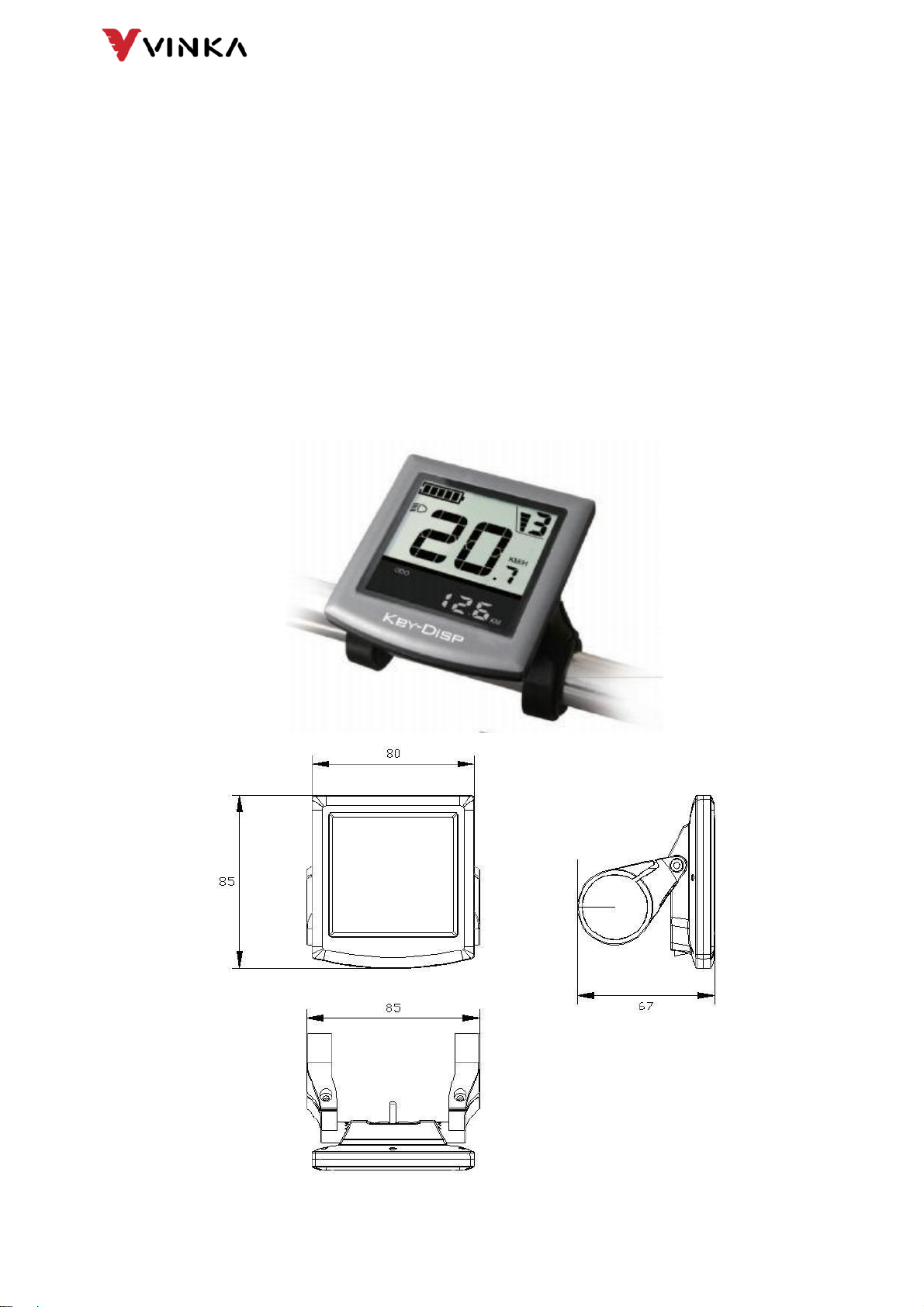
Appearance and Size.........................................................................................................................2
Button definition.................................................................................................................................3
Function summary and layout............................................................................................................4
◆
Function summary ..................................................................................................................4
◆
Function Layout ......................................................................................................................4
General Operation..............................................................................................................................5
1.Switching the E-bike System On/Off.......................................................................................5
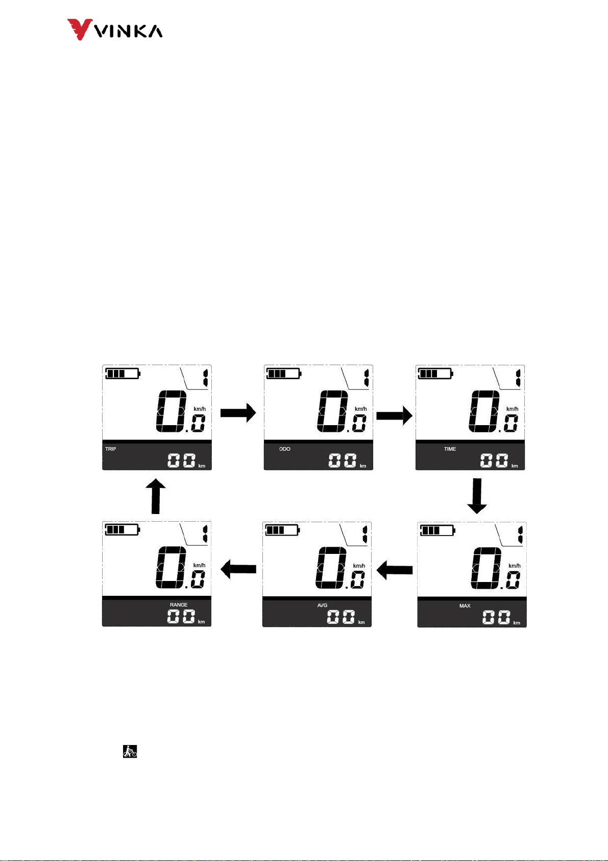
2.Display Interface......................................................................................................................5
3.Switching Push-assistance Mode On/Off................................................................................5
4.Switching the Lighting On/Off..................................................................................................6
5.Assist Level Options................................................................................................................6
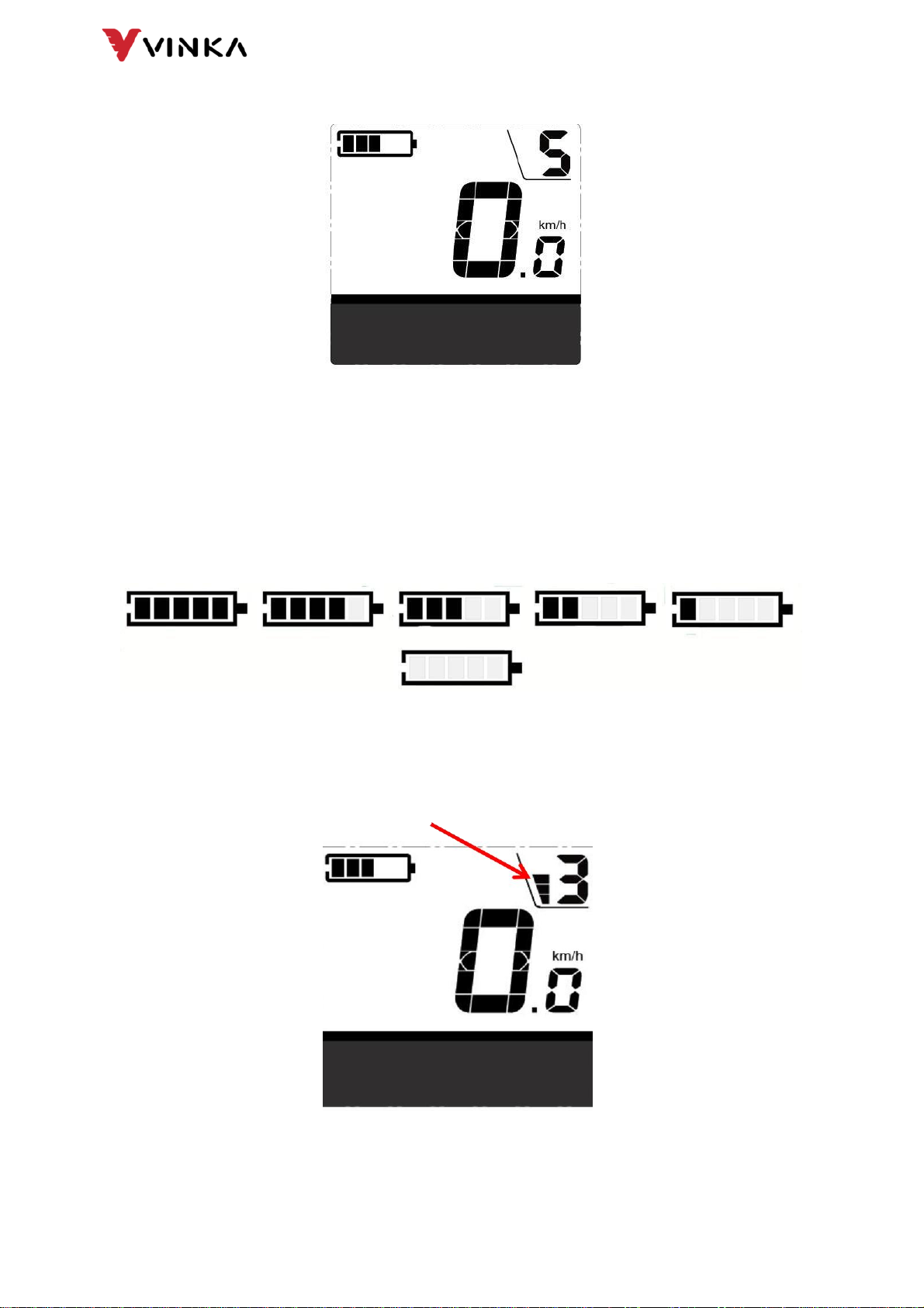
6.Battery Indicator.......................................................................................................................7
7.Motor Power Indicator.............................................................................................................7
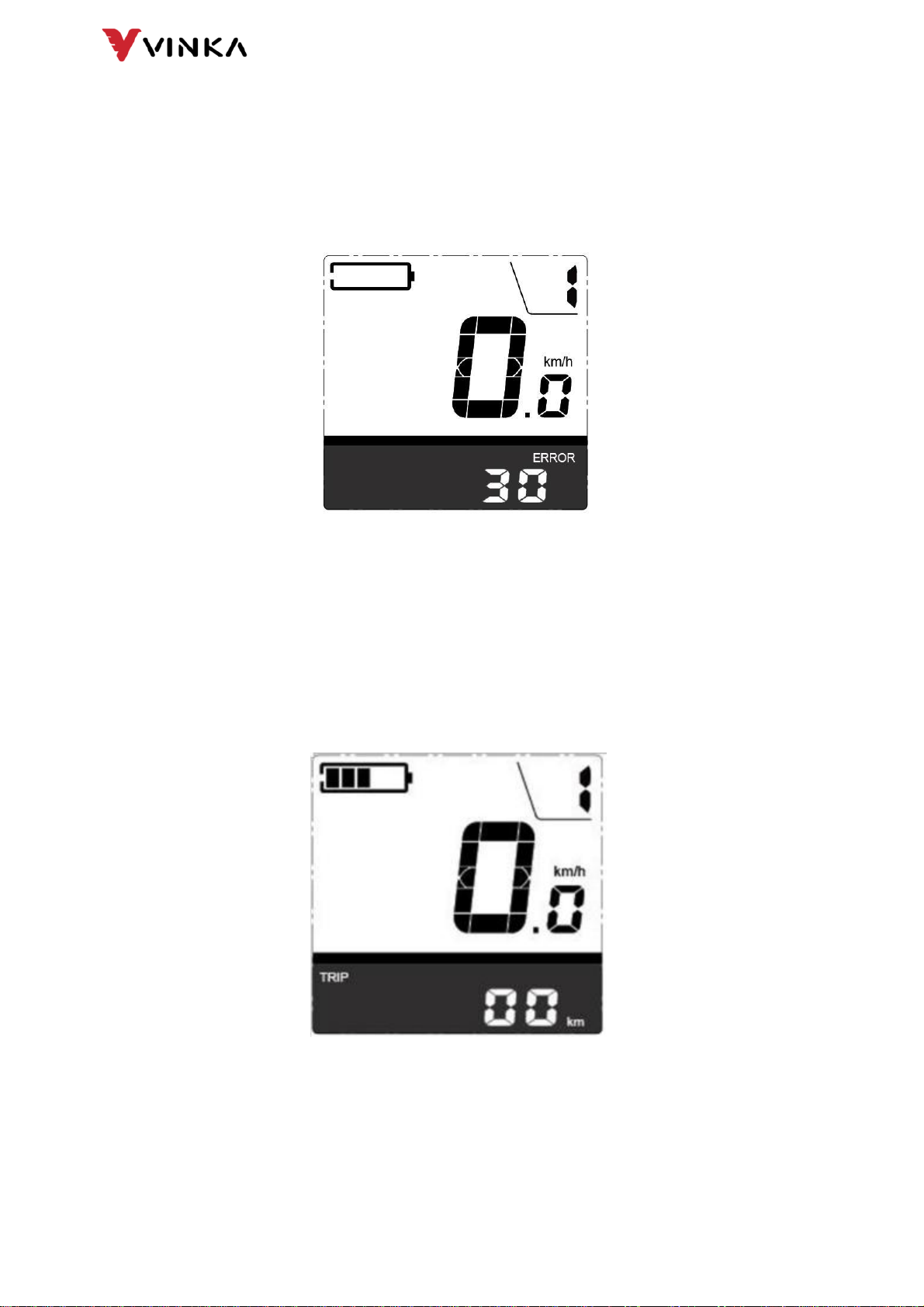
8.Error Code Indication...............................................................................................................8
9.Trip Distance Clearance..........................................................................................................8
General Settings................................................................................................................................9
1.Backlight Settings....................................................................................................................9
2. Unit settings............................................................................................................................9
3.Wheel Diameter Settings.......................................................................................................10
4.Speed-limit Settings...............................................................................................................10
5.Walk Speed setting...............................................................................................................10
6. software version...................................................................................................................10
Quality assurance and warranty scope:...........................................................................................11
I.
Warranty:...............................................................................................................................11
II.
Others ...................................................................................................................................11
The following cases do not belong to warranty scope:..........................................................11
Wire connection layout.....................................................................................................................11
Connector wire sequence.........................................................................................................11
Wire sequence table .................................................................................................................11
Warnings:.........................................................................................................................................12
Attached list 1:Error Code Definition.............................................................................................12
Attached list 2:Assist level ratio defaults.......................................................................................12

2
苏州万佳电器有限公司
Suzhou wanjia Electric Co.,Ltd.
Product Name and Model
Intelligent Segment LCD display of E-bike
Model: DC21.
Specifications
●
Rated voltage: 24V/36V/48V
Rated working current: 10mA
●
Maximum working current: 30mA
●
Off-state leakage current: <1uA
●
Operating temperature: -20℃~60℃
●
Storage temperature: -30℃~ 70℃
Appearance and Size
◆
Display appearance and dimensional drawing (unit: mm)

3
苏州万佳电器有限公司
Suzhou wanjia Electric Co.,Ltd.
Button definition
DC21 has four buttons:
Power button is on the top of the left button.
Light/plus button “+”, MODE button “i”, and minus button “-” are on the
Independent left button. In this manual we use words “ON/OFF”, “UP”, “MODE” and
“DOWN” to represent these 4 buttons.

4
苏州万佳电器有限公司
Suzhou wanjia Electric Co.,Ltd.
Function summary and layout
◆
Function summary
DC21 has many functions to meet the riders’ needs. The indicating elements are as
follows:
●
Smart battery indication
●
Assist level
●
Speed indication (incl. Current speed, max. speed and avg. speed)
●
ODO and trip
●
The push-assistance function
●
Trip time
●
The lighting On/Off
●
Error code indication
●
Motor power
●
Range
●
Various parameters settings (e.g., wheel size, speed-limited, battery level bar, Assist
level, controller limited current, max speed, password enable, etc.)
●
Recover default settings
◆
Function Layout
Functional Area Distribution

5
苏州万佳电器有限公司
Suzhou wanjia Electric Co.,Ltd.
General Operation
1.Switching the E-bike System On/Off
To switch on the E-bike system and provide the power supply to the controller, hold the
On/Off button on the remote for 1 s.
To switch off the E-bike system, hold the On/Off button for 1s. The E-bike system no
longer uses the battery power.
When E-bike system is switched off, the leakage current is less than 1 μA.
■
When the E-bike is parked for over 15 minutes, the E-bike system switches off
automatically.
2.Display Interface
After switching on the E-bike system, the display will show Current Speed and TRIP by
default.
Press “i” button on the remote to switch between the indication functions below:
Trip Distance (Km)→ODO (Km)→Trip Time (min)→Max. Speed (Km/h) →Avg. Speed
(Km/h) → RANGE (Km)
Display interface
3.Switching Push-assistance Mode On/Off
■
To activate the push-assistance function, short press the MODE button and hold the DOWN
button between 3S.The E-bike is activated with a uniform speed while the screen displays
shown “ ”. (Without special settings, the E-bike will start at a constant speed at a standard
speed of 6km/h by default).
■
The push-assistance function will be switched off as soon as you release the DOWN button
and E-bike gets back to the status before the push-assistance is engaged.

6
苏州万佳电器有限公司
Suzhou wanjia Electric Co.,Ltd.
Push-assistance
Mode
⬛Push-assistance function may only be used when pushing the E-bike. Be aware of
danger of injury when the wheels of the E-bike do not have ground contact while
using the push-assistance function.
4.Switching the Lighting On/Off
To switch on bike light, hold the UP button for 1s. The lighting icon comes out and display
backlight brightness is automatically reduced.
Likewise, hold the UP button for 1s again, the bike light switches off. The lighting icon is gone
and display resumes backlight brightness.
Switch the Lighting On/Off Interface
5.Assist Level Options
The assist level of the E-bike drive can be changed anytime, even during riding.Press the UP or
DOWN button to switch between the assist levels and change the motor output power
The assist level ranges from 0 to 5 (level 0 to level 5). The default assist level is “1” when the
display is started. The output power is zero on Level “0”. Level “1” is the minimum output power.
Level “5” is the maximum output power.

7
苏州万佳电器有限公司
Suzhou wanjia Electric Co.,Ltd.
Assist Level “5”
6.Battery Indicator
The five battery bars represent the capacity of the battery. Each bar is equivalent to a
capacity of approx. 20%. The five battery bars are bright when the battery is in full voltage.
When the battery is in low voltage, battery frame will flash to give a notice that the battery needs
to be recharged immediately.
7.Motor Power Indicator
Battery Indicator
The power of the motor can be read via below interface.
Motor Power Indication
Flash in low voltage

8
苏州万佳电器有限公司
Suzhou wanjia Electric Co.,Ltd.
8.Error Code Indication
The components of the E-bike system are continuously and automatically monitored.
When an error is detected, the respective error code is indicated in text indication area.
Refer to the detail message of the error codes in Attached list 1.
Error Code Indication
⬛
Have the display inspected and repaired when an error code appears. Or else, you
will not be able to ride the bike normally. Please always refer to an authorized bicycle
dealer
9.Trip Distance Clearance
On the TRIP page, press the DOWN button and the UP button at the same time for
more than 1 second, the indicator enters the TRIP reset function, and at the same
time, the TRIP value is reset to zero.
Trip Distance Clearance Settings Interface

9
苏州万佳电器有限公司
Suzhou wanjia Electric Co.,Ltd.
General Settings
To access Setting interface, hold both the MODE button and the DOWN button
simultaneously for 1s.
All the settings are implemented on a parked bike of no speed.
1.Backlight Settings
The settable range is from Level 1 to Level 5. Level 1 is the darkest, Level 5 is the brightest.
The default value is decided by the controller when the display leaves factory. Press the
UP/DOWN button to change the brightness levels. Press the MODE button to confirm and
exit the settings.
Backlight Brightness Settings Interface
2. Unit settings
U represents unit settings, “1” is mile and “0”is kilometer. The default value is “0”.
Enter the UNIT Type, press the UP or DOWN button to choose the desired setting item,
and then press the MODE button to confirm and store the changed settings.
Mile toggling Settings Inter

10
苏州万佳电器有限公司
Suzhou wanjia Electric Co.,Ltd.
3.Wheel Diameter Settings
DL represents wheel diameter settings. Wheel SIZE represents wheel diameter.
The wheel size is only for your information, not settable.
Wheel Diameter Settings Interface
4.Speed-limit Settings
SP represents the limited speed settings. When the current speed is faster than speed
limit, the E-bike system will switch off automatically. Speed limit range is 5Km/h to 46Km/h.
The default value is 29Km/h. The Speed limit is only for your information, not settable
Speed Limit Settings Interface
5.Walk Speed setting
PS refers to push-assist mode speed. The settable range is 3-6 km/h. 3km/h is the
slowest while 6km/h is the fastest. The default push-assist speed is decided by the
controller.
Press the UP/DOWN button to increase or decrease the speed limit to your desired
value. Hold the MODE button 1s to confirm and exit the settings status.
6. software version
CL refers to the motor software version of this E-bike.
DP refers to the display software version of this E-bike

11
苏州万佳电器有限公司
Suzhou wanjia Electric Co.,Ltd.
Quality assurance and warranty scope:
I.
Warranty:
1)
The warranty will be valid only for products used in normal usage and conditions.
2)
The warranty is valid for 24 months after the shipment or delivery to the customer.
II.
Others
The following cases do not belong to warranty scope:
1)
The display is demolished.
2)
The damage of the display is caused by wrong installation or operation.
3)
The shell of the display is broken after the display is out of the factory.
4)
The cable of the display is broken.
5)
Beyond warranty period.
6)
The fault or damage of the display is caused by the force majeure (e.g., fire,
earthquake, etc.).
Wire connection layout
Connector wire sequence
Connector to controller display connector mating connector to display
Wire sequence table
Wire sequence
Color
Function
1
Red(VCC)
+
2
Blue(K)
Lock
3
Black(GND)
-
4
Green(RX)
RX
5
Yellow(TX)
TX
■
Some displays have wire connection with water-proof connectors, users can
not see the color of lead wires in the harness.

12
苏州万佳电器有限公司
Suzhou wanjia Electric Co.,Ltd.
Warnings:
1.
Use the display with caution. Don’t attempt to disconnect or link the connector when
battery is power on.
2.
Try to avoid hitting the display.
3.
Don’t modify system parameters to avoid parameter disorder.
4.
Make the display repaired when an error code appears.
■This manual instruction is a universal version for DISPLAY DC21. Some versions of this
display may be different from specification to specification as to the software. Please always
refer to an actual version.
Attached list 1:Error Code Definition
Error Code
Definition
21
Current Abnormality
22
Throttle Abnormality
23
Motor Phase Abnormality
24
Motor Hall Signal Abnormality
25
Brake Abnormality
30
Communication
Abnormality
Attached list 2:Assist level ratio defaults
Level
PASlevel
mode
1
2
3
4
5
6
7
8
9
0-3/1-3
50%
74%
92%
—
—
—
—
—
—
0-5/ 1-5
50%
61%
73%
85%
96%
—
—
—
—
0-7/ 1-7
40%
50%
60%
70%
80%
90%
96%
—
—
0-9/ 1-9
25%
34%
43%
52%
61%
70%
79%
88%
96%
Table of contents
Other VINKA Monitor manuals