VINKA DR25 User manual

苏州万佳电器有限公司
Suzhou wanjia Electric Co.,Ltd.
DR25
VINKA Display
User Manual

苏州万佳电器有限公司
Suzhou wanjia Electric Co.,Ltd.
Contents
1. Product name and model........................................................................ 1
2. Specifications ......................................................................................... 1
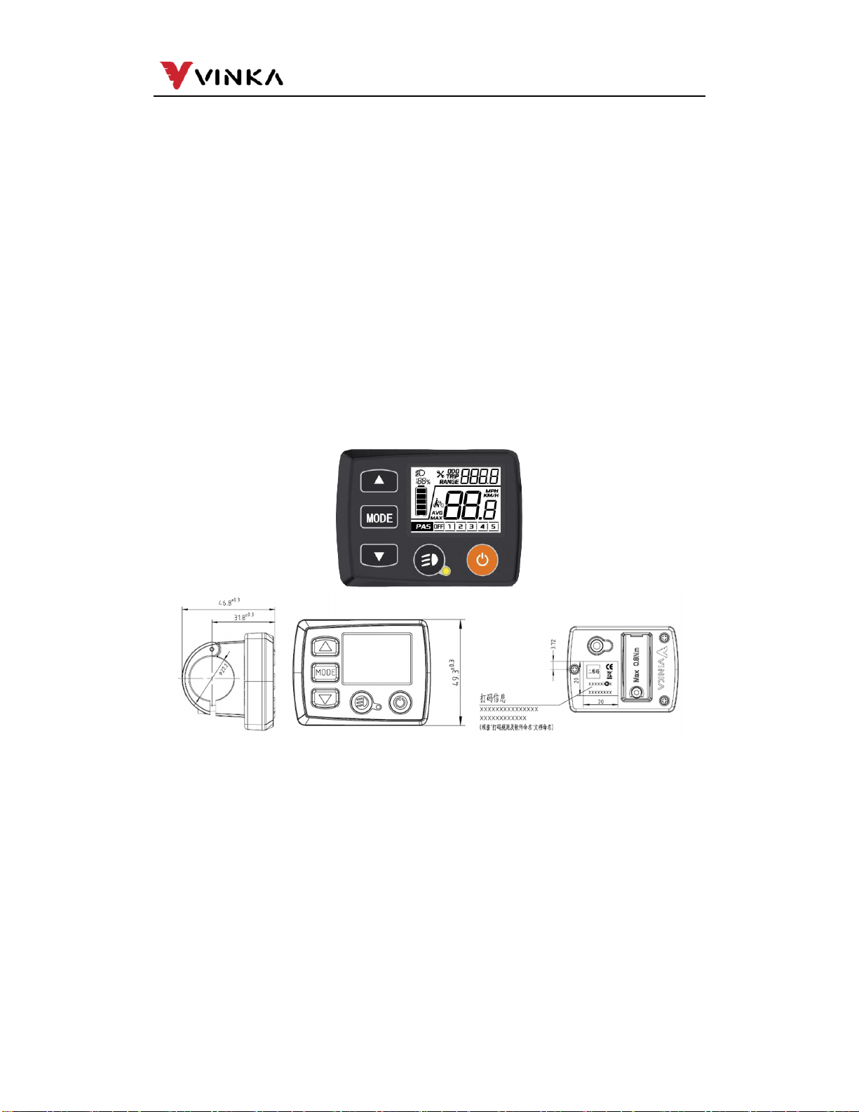
3. Appearance and Size ............................................................................. 1
4. Functuion Summary................................................................................ 1
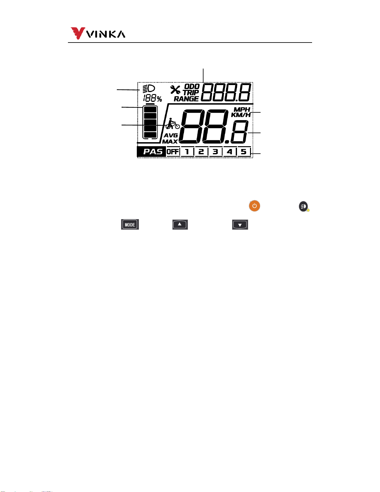
5. Function Area Distribution....................................................................... 2
6. Button Definition ..................................................................................... 2
7. Installation .............................................................................................. 2
8. General Operation .................................................................................. 2
(1).Switching the E-bike System mode ON/OFF .................................... 3
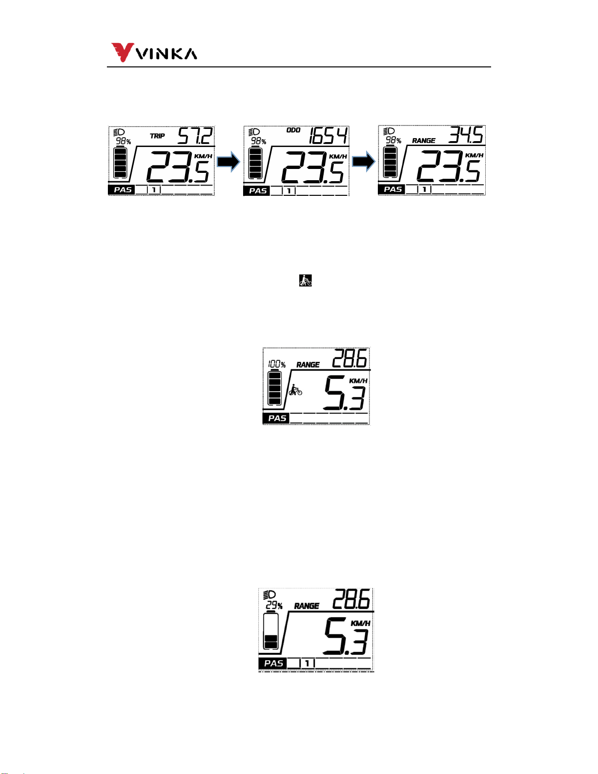
(2).Display Interface................................................................................ 3
(3).Switching Push-assisttance Mode ON/OFF ...................................... 3
(4).Switching the Lighting ON/OFF......................................................... 3
(5).Assist Level Selection ....................................................................... 4
(6).Battery Indicatorr............................................................................... 4
(7).Error Code Indication ........................................................................ 4
9. General Setting....................................................................................... 5
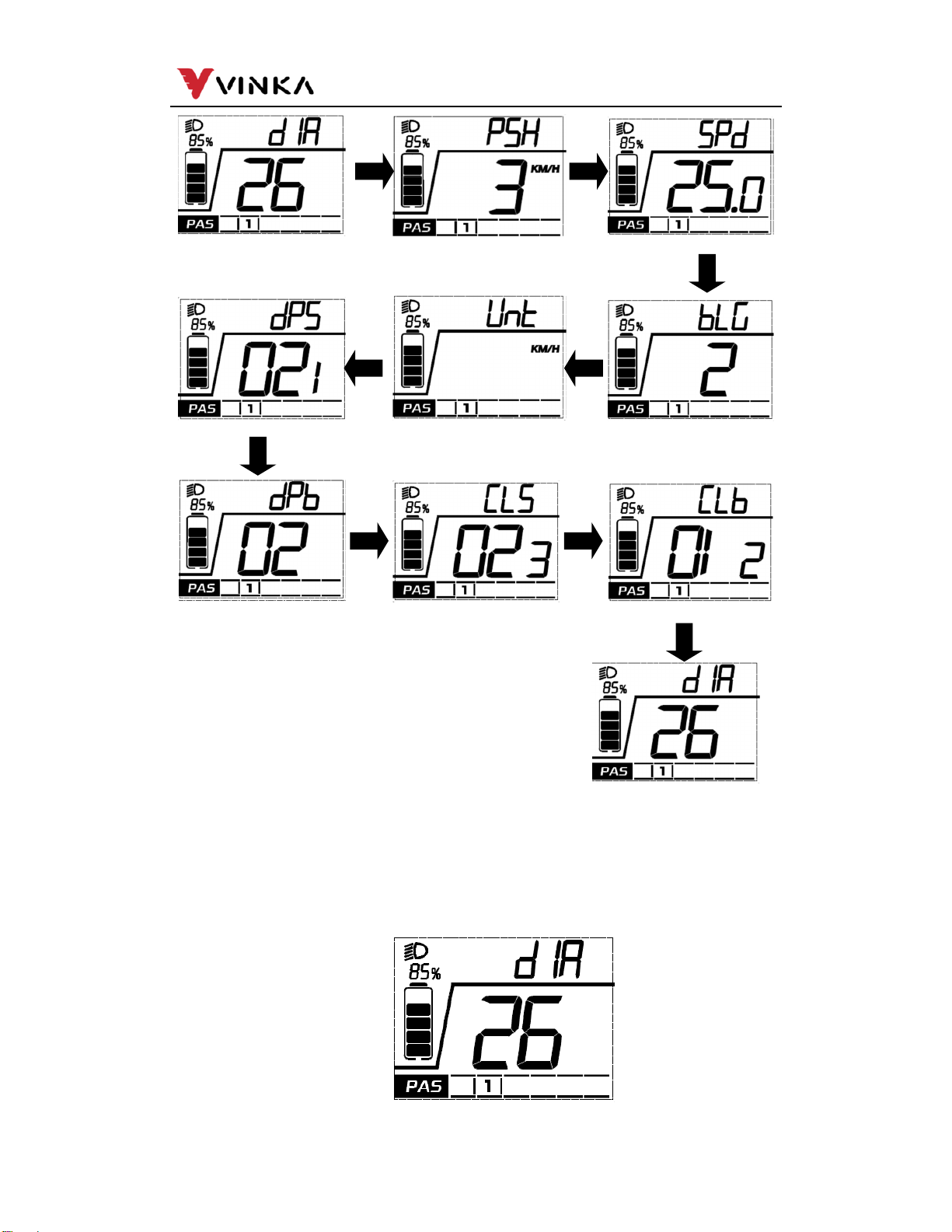
(1).Settings Interface .............................................................................. 5
(2).Wheel size settings ........................................................................... 6
(3).Software version of Controller ........................................................... 7
(4).Software version of Display............................................................... 7
(5).Toggle unit settings............................................................................ 7
(6).LCD Brightness ................................................................................. 8
(7).Speed Limitation Info......................................................................... 8
(8).Push-assistance................................................................................ 8
(9).TRIP clear function............................................................................ 9
(10).Exit settings..................................................................................... 9
Quality Assurance and Warranty Scope ................................................... 10
Connection Layout ..................................................................................... 10
Warnings...................................................................................................... 11
Attached list 1: Error code definition ........................................................ 12
Attached list 2: Display character corresponding function .................... 13

1
苏州万佳电器有限公司
Suzhou wanjia Electric Co.,Ltd
.
1. Product name and model
E-bike Intelligent LCD display
Model: DR25
2. Specifications
36V/48V Power Supply
The maximum working current: 30mA
Off-state leakage current: <1μA
Operating temperature: -20℃~ 60℃
Storage temperature: -30℃~ 80℃
3. Apperance and Size
Product appearance and dimensional drawing (unit: mm)
4. Function Summary
DR25 display has many functions to meet the user’s needs. The indicating
contents are as follows:
Smart battery SOC, real-time voltage or percentage, optional
Intelligent indication of Trip, ODO, RT speed, Max Speed, Avg Speed
Assist level adjustment and indication
Backlight control and lighting indicator
The push-assist control and indication
Error code indication
Various Parameters Setting/Info (e.g. Unit toggling, wheel size info, speed limit
info, assist level mode info etc.)

2
苏州万佳电器有限公司
Suzhou wanjia Electric Co.,Ltd
.
5. Function Area Distribution
6. Button definition
There are five buttons on DR25 display: power button , light button ,
MODE button , UP button , DOWN button . In this manual we use
words “ON/OFF”, “Light” , ”MODE”, “UP”and “DOWN” to represent these 5 buttons.
7. Installation
DR25 can be mounted on the left side of handlebar close to its grip. Adjust the
angle for a good screen view. Cut off the power before connecting the corresponding
connectors between display and controller.
8. General Operation
Switching the E-bike System mode ON/OFF
To switch on the E-bike system and provide the power supply to the controller, hold the
ON/OFF button for 1s.
To switch off E-bike system, hold the ON/OFF button for 1s. The E-bike system no
longer uses the battery power.
When E-bike system is switched off, the leakage current is less than 1 μA.
When the E-bike is parked for over 15 minutes, the E-bike system switches
off automatically.
Display Interface
After switching on the E-bike system, the display will show Real-time Speed and
Trip Distance, ODO, battery SOC by default.
Assist-level
Light
Push-assist
BatteryInterface
SpeedInfo
UnitInfo
GeneralfunctionInfo
Function Info

3
苏州万佳电器有限公司
Suzhou wanjia Electric Co.,Ltd
.
Press the “MODE” button and switch between:
TRIP(Km)→ODO(Km)→RANGE(Km) →Trip (Km)
Switching Push-assist Mode On/Off
To activate the push-assistance function, short press MODE button and hold the
DOWN button between 3S. E-bike is activated with a uniform speed of 6 km/h
while the screen displays shown “ ”.
The push-assistance function will be switched off as soon as you release the
DOWN button and ebike gets back to the status before the push-assistance is
engaged.
Push-assist function may only be used when pushing the E-bike. Be
aware of danger of injury when bike wheels do not have ground
contact while using the push-assist function.
Switching Lighting ON/OFF
To switch on bike light, short press Light button. The lighting icon comes out
and display backlight brightness is automatically reduced.
Likewise, short press the Light button again, the bike light switches off. The
lighting icon is gone and display resumes backlight brightness.
Assist Level Selection
Display interface
Push-assistance mode
Switching the Lighting Mode On/Off Interface

4
苏州万佳电器有限公司
Suzhou wanjia Electric Co.,Ltd
.
Press UP or DOWN button to switch between the assist levels and change
the motor output power, The default assist level ranges from level “OFF” to level
“5”, The output power is zero on Level “OFF”. Level “1” is the minimum power.
Level “5” is the maximum power.
Battery Indicator
The default voltage of display battery is 36V.The segmented voltage values
are 31.5V-32.5V-34.35V-36.03V-37.48V-39.46V.
Error Code Indication
The components of the E-bike system are continuously and automatically
monitored.
When an error is detected, the respective error code is indicated in text
indication area.
Refer to detailed definition of the error codes in Attached list 1.
Have the display inspected and repaired when an error code appears.
Assist Level Interface
Battery SOC Indicator interface
Error Code Indication

5
苏州万佳电器有限公司
Suzhou wanjia Electric Co.,Ltd.
Or else, you will not be able to ride the bike normally. Please always
refer to an authorized bicycle dealer.
9. General Settings
Press the ON/OFF button to switch on the display.
To access Setting interface , hold both the “MODE” button and the “DOWN” button
simultaneously for 1S.
All the settings are implemented on a parked bike of no speed.
Settings Interface
In the power on state, long press the the MODE and DOWN button to enter the
settings interface, and short press the UP or DOWN button to switch the setting
interface. In any setting interface, short press the MODE button to enter the
parameter editing state, and the corresponding parameters enter the flashing state.
The flashing frequency is 1Hz. At this time, short press the UP or DOWN button to
modify the parameters. Long press the MODE button to save and exit the editing
state, and the parameters stop flashing. Press and hold the MODE button again to
exit the setting interface and return to the main interface.
In the setting interface, short press the MODE button to enter the next menu, and
long press the MODE button to return to the previous menu.
Short press the UP or DOWN button, and each interface will enter the setting and
reading information status in the following order

6
苏州万佳电器有限公司
Suzhou wanjia Electric Co.,Ltd
.
Wheel Size settings
DIR represents wheel diameter.
The wheel size is only for your information, not settable.
Hold “MODE” button to return to home page.
Wheel Size Info
Wheel Size Interface Push-assist Interface S
p
eed Limitation Interface
LCD Brightness Interface
Unit Interface
Software version of Dis
p
la
y
Interface
Software version of Controller Interface Version of Controller Interface Version of Controller Boot Interface
Wheel Size Interface

7
苏州万佳电器有限公司
Suzhou wanjia Electric Co.,Ltd.
Software version of Controller
CLS represents the software version of controller. The software version of
controller is uploaded by the controller, and the display can’t be adjusted.
Software version of Display
dPS represents the software version of display. The software version of diaplay
is uploaded by the controller
Toggle unit settings
UNT represents change unit between Metric and Imperial . The default is “Metric”
Short press the MODE button to enter the unit switching mode, short press the
UP/DOWN to convert the speed and mileage units, long press the MODE button
to confirm and exit the normal setting state.
Software version of Controller Info
Software version of Display Info
Toggle unit settings

8
苏州万佳电器有限公司
Suzhou wanjia Electric Co.,Ltd
.
LCD Brightness
BLG represents
Backlight level settings. The settable range is Level 1, Level 2 ,
Level 3 , Level 4 , Level 5. Level 1 is the darkest, Level 3 is standard and Level 5 is
the brightest. The default value is decided by the controller when the display leaves
factory. Press UP/DOWN to change the brightness levels. Hold the ON/OFF button
to confirm and exit the settings.
Speed Limitation Info
Speed limitation value is just for your information, not settable
Push-assistance
PSH represents push-assistance. The selectable range of push-assist setting
value is between 3km / h and 6km / h. short press the UP/DOWN button to set
up / down. The maximum riding speed of the display is uploaded by the
controller. Press the UP/DOWN button to increase or decrease the speed limit
value until the required speed limit value is displayed; Long press the MODE
button for more than 1s to confirm and exit the setting state.
Speed Limitation Info
Brightness settings
Push-assistance Info

9
苏州万佳电器有限公司
Suzhou wanjia Electric Co.,Ltd.
TRIP clear function
In TRIP mode and Trip is not 0, press the UP and DOWN buttons at the same
time for more than 1 second to clear the trip data information.
Exit settings
In personalized parameter settings interface, Short press the MODE button is to
confirm the input.
Hold the MODE button is to store the settings.

10
苏州万佳电器有限公司
Suzhou wanjia Electric Co.,Ltd.
Quality assurance and warranty scope
ⅠWarranty
1) The warranty will be valid only for products used in normal usage and conditions.
2) The warranty is valid for 24 months after the shipment or delivery to the customer.
ⅡOthers
The following cases do not belong to warranty scope:
1) The display is demolished.
2) The damage of the display is caused by wrong installation or operation.
3) The shell of the display is broken after the display is out of the factory.
4) The cable of the display is broken.
5) Beyond warranty period.
6) The fault or damage of the display is caused by the force majeure (e.g., fire,
earthquake, etc.)
Connection Layout
①Outlet diagram that comes with the display
Wire sequence table

11
苏州万佳电器有限公司
Suzhou wanjia Electric Co.,Ltd.
Wire serial Code Function
1
BAT
Battery power wire
2
GND
Ground wire
3
DTX Data transmission wire of the display
4
DRX Data receiving wire of the display
5
ON-OFF Controller power control wire
6 Walk
Push control wire
displays have wire connection with water-proof connectors,
users can not see the pin wire colors.
Warnings:
1.Use the display with caution. Don’t attempt to release or link the connector when
battery is power on.
2.Try to avoid hitting the display.、
3.Don’t modify system parameters to avoid parameter disorder.
4.Make the display repaired when error code appears.
■This manual instruction is a universal version for VINKA DR25 display. Software specific,
versions of this display may be different. Please always refer to an actual version.

12
苏州万佳电器有限公司
Suzhou wanjia Electric Co.,Ltd.
Attached list 1: Error code
definition
Error code Definition
90
Torque Zero Error
11
Torque Out Range
92
Torque Sensor Fault
13
Gear Sensor Error
15
Speed Sensor Error
18
Cadence Error
20
PCB Over-Temp Warning
A1
PCB Over-Temp Error
22
PCB Sensor Fault
25
Motor Over-Temp Warning
A6
Motor Over-Temp Error
A7
Flash Error
80
Communication Lost
32
LORA Communication Lost
01
Communication CRC Error
40
Motor EST Error
41
Motor Over-Peak Current
C2
Motor Loss Phase
43
Motor Over DC Current
D0
Battery Over Voltage
51
Battery Low Voltage
52
Battery Over Current
E0
Battery Version Error
E5
Display Version Error

13
苏州万佳电器有限公司
Suzhou wanjia Electric Co.,Ltd.
Attached list 2: Display character corresponding function
Character Definition
1
Wheel Size
2
SoftWare of Controller
3
Controller boot version
4
Software of Display
5
Toggle Unit settings
6
Brightness Level
7
Speed Limitation
8
Push-assistance Speed
Table of contents
Other VINKA Monitor manuals