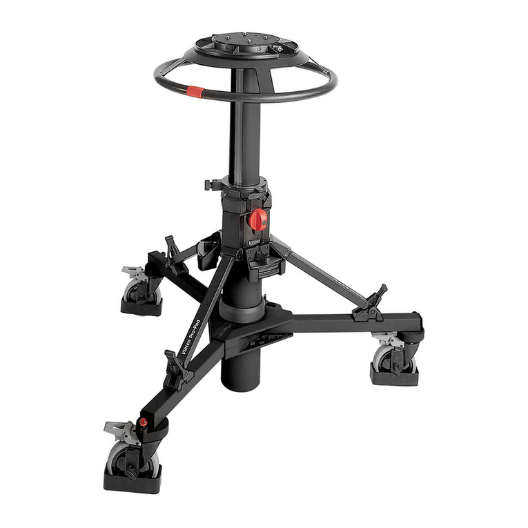
Vinten Fulmar Pedestal User manual

2
Contents
Previous
Page
First
Page
Next
Page
Previous
View
Fulmar
PEDESTAL
3702
MAINTENANCE MANUAL
AND
ILLUSTRATED PARTS LIST
PUBLICATION PART No. 3702-9
ISSUE 14
Copyright © Vinten Broadcast Limited 2001
All rights reserved throughout the world. No part of this document may be stored in a retrieval system,
transmitted, copied or reproduced in any way including, but not limited to, photocopy, photograph, magnetic or
other record without the prior agreement and permission in writing of Vinten Broadcast Limited.
Vinten is a registered trademark of Vinten Broadcast Limited.

3
Contents
Previous
Page
First
Page
Next
Page
Previous
View
Foreword
This manual provides full and detailed maintenance and spare parts information for the Vinten®Fulmar
pedestal. The Fulmar pedestal is an obsolete product and this Maintenance Manual is provide for the final
production version.
It is recommended that this manual is read carefully and the illustrations studied prior to operating or servicing
the pedestal. Attention to the details contained herein will ensure that the pedestal will operate efficiently with
the minimum of attention over a long service life. Particular attention must be paid to cleaning, especially after
use in adverse conditions.
To order spare parts or to obtain further information, application should be made to Vinten Broadcast Limited
or to your local distributor, or visit our website at www.vinten.com.
WARNING!: Read the Safety Section on page 5 before using this pedestal or attempting
any adjustment or repair.

4
Contents
Previous
Page
First
Page
Next
Page
Previous
View
Notes to readers
This is an on-line version of ‘Fulmar Pedestal Maintenance Manual’ (3702-9). The Fulmar pedestal is an
obsolete product and this Maintenance Manual is provide for the final production version.
Navigation
Clicking the mouse on any blue text will move you around the document. For example, if you click on one of
the blue call-outs on an exploded drawing, you will be taken to the appropriate line in the relevant parts list.
Clicking here will take you to the Contents Page.
Clicking here will take you to the first page.
Clicking here will take you to the previous page.
Clicking here will take you to the next page.
Click here to go back to the previous view.
Alternatively, you may use the Acrobat Reader navigation buttons.
Contents

5
Contents
Previous
Page
First
Page
Next
Page
Previous
View
Safety - Read This First!
Warning symbols in this maintenance manual
Where there is a risk of personal injury, injury to others, or damage to the pedestal or
associated equipment, comments appear, highlighted by the word WARNING! and
supported by the warning triangle symbol.
Warning symbols on the pedestal
On encountering the warning triangle and open book symbols it is imperative that you
consult this maintenance manual before using this pedestal or attempting any adjustment
or repair.
Critical data
Mass
Pedestal 173 kg (383 lb)
Trim weights (total) 7.5 kg (16.5 lb)
Load
Minimum Load 23 kg (50 lb)
Maximum Load 158 kg (350 lb)
Pressure
Maximum pressure 19.3 bar (280 psi)
158 kg
173 kg
≤19.3 bar

6
Contents
Page
Previous
Page
First
Page
Next
Page
Previous
View
Foreword . . . . . . . . . . . . . . . . . . . . . . . . . . . . . . . . . . . . . . . . . . . . . . . . . . . . . . . . . . . . . . . . . . . . . . . . . . . . 3
Notes to readers . . . . . . . . . . . . . . . . . . . . . . . . . . . . . . . . . . . . . . . . . . . . . . . . . . . . . . . . . . . . . . . . . . . . . . 4
Safety - Read This First! . . . . . . . . . . . . . . . . . . . . . . . . . . . . . . . . . . . . . . . . . . . . . . . . . . . . . . . . . . . . . . . . 5
Abbreviations . . . . . . . . . . . . . . . . . . . . . . . . . . . . . . . . . . . . . . . . . . . . . . . . . . . . . . . . . . . . . . . . . . . . . . . . 8
Technical Specification . . . . . . . . . . . . . . . . . . . . . . . . . . . . . . . . . . . . . . . . . . . . . . . . . . . . . . . . . . . . . . . . 9
Design Improvements. . . . . . . . . . . . . . . . . . . . . . . . . . . . . . . . . . . . . . . . . . . . . . . . . . . . . . . . . . . . . . . . . 14
Section 1 - Introduction and Description
Introduction . . . . . . . . . . . . . . . . . . . . . . . . . . . . . . . . . . . . . . . . . . . . . . . . . . . . . . . . . . . . . . . . . . . . . . . 15
Description . . . . . . . . . . . . . . . . . . . . . . . . . . . . . . . . . . . . . . . . . . . . . . . . . . . . . . . . . . . . . . . . . . . . . . . . 15
Section 2 - Operation
General . . . . . . . . . . . . . . . . . . . . . . . . . . . . . . . . . . . . . . . . . . . . . . . . . . . . . . . . . . . . . . . . . . . . . . . . . . . 19
Putting into service . . . . . . . . . . . . . . . . . . . . . . . . . . . . . . . . . . . . . . . . . . . . . . . . . . . . . . . . . . . . . . . . . 20
Operation . . . . . . . . . . . . . . . . . . . . . . . . . . . . . . . . . . . . . . . . . . . . . . . . . . . . . . . . . . . . . . . . . . . . . . . . . 22
Section 3 - Tools and Materials
Special tools. . . . . . . . . . . . . . . . . . . . . . . . . . . . . . . . . . . . . . . . . . . . . . . . . . . . . . . . . . . . . . . . . . . . . . . 24
Consumable materials. . . . . . . . . . . . . . . . . . . . . . . . . . . . . . . . . . . . . . . . . . . . . . . . . . . . . . . . . . . . . . . 24
Section 4 - Servicing
General . . . . . . . . . . . . . . . . . . . . . . . . . . . . . . . . . . . . . . . . . . . . . . . . . . . . . . . . . . . . . . . . . . . . . . . . . . . 25
Cleaning . . . . . . . . . . . . . . . . . . . . . . . . . . . . . . . . . . . . . . . . . . . . . . . . . . . . . . . . . . . . . . . . . . . . . . . . . . 25
Servicing. . . . . . . . . . . . . . . . . . . . . . . . . . . . . . . . . . . . . . . . . . . . . . . . . . . . . . . . . . . . . . . . . . . . . . . . . . 26
Adjustments . . . . . . . . . . . . . . . . . . . . . . . . . . . . . . . . . . . . . . . . . . . . . . . . . . . . . . . . . . . . . . . . . . . . . . . 29
Section 5 - Repair
General . . . . . . . . . . . . . . . . . . . . . . . . . . . . . . . . . . . . . . . . . . . . . . . . . . . . . . . . . . . . . . . . . . . . . . . . . . . 33
Disassembly . . . . . . . . . . . . . . . . . . . . . . . . . . . . . . . . . . . . . . . . . . . . . . . . . . . . . . . . . . . . . . . . . . . . . . . 34
Assembly . . . . . . . . . . . . . . . . . . . . . . . . . . . . . . . . . . . . . . . . . . . . . . . . . . . . . . . . . . . . . . . . . . . . . . . . . 38
Other replacements . . . . . . . . . . . . . . . . . . . . . . . . . . . . . . . . . . . . . . . . . . . . . . . . . . . . . . . . . . . . . . . . .44

7
Contents
Previous
Page
First
Page
Next
Page
Previous
View
Section 6 - Illustrated Parts List
Introduction . . . . . . . . . . . . . . . . . . . . . . . . . . . . . . . . . . . . . . . . . . . . . . . . . . . . . . . . . . . . . . . . . . . . . . . 45
Ordering spare parts . . . . . . . . . . . . . . . . . . . . . . . . . . . . . . . . . . . . . . . . . . . . . . . . . . . . . . . . . . . . . . . . 45
Main assembly part numbers . . . . . . . . . . . . . . . . . . . . . . . . . . . . . . . . . . . . . . . . . . . . . . . . . . . . . . . . . 46
Illustrations Page
Fig 1.1 Fulmar pedestal . . . . . . . . . . . . . . . . . . . . . . . . . . . . . . . . . . . . . . . . . . . . . . . . . . . . . . . . . . . . . . . 16
Fig 1.2 Pneumatic system - schematic diagram . . . . . . . . . . . . . . . . . . . . . . . . . . . . . . . . . . . . . . . . . . . . . 18
Fig 2.1 Pressurization graph. . . . . . . . . . . . . . . . . . . . . . . . . . . . . . . . . . . . . . . . . . . . . . . . . . . . . . . . . . . . 21
Fig 4.1 Chain tension adjustment . . . . . . . . . . . . . . . . . . . . . . . . . . . . . . . . . . . . . . . . . . . . . . . . . . . . . . . . 27
Fig 4.2 Wheel alignment . . . . . . . . . . . . . . . . . . . . . . . . . . . . . . . . . . . . . . . . . . . . . . . . . . . . . . . . . . . . . . . 29
Fig 4.3 Column guide roller adjustment . . . . . . . . . . . . . . . . . . . . . . . . . . . . . . . . . . . . . . . . . . . . . . . . . . . 30
Fig 4.4 Steering ring adjustment. . . . . . . . . . . . . . . . . . . . . . . . . . . . . . . . . . . . . . . . . . . . . . . . . . . . . . . . . 31
Fig 5.1 Arrangement of cords and chains in the column . . . . . . . . . . . . . . . . . . . . . . . . . . . . . . . . . . . . . . 38
Fig 6.1 Fulmar Pedestal . . . . . . . . . . . . . . . . . . . . . . . . . . . . . . . . . . . . . . . . . . . . . . . . . . . . . . . . . . . . . . . 47
Fig 6.2 Fulmar Pedestal - Top Tube . . . . . . . . . . . . . . . . . . . . . . . . . . . . . . . . . . . . . . . . . . . . . . . . . . . . . . 49
Fig 6.3 Fulmar Pedestal - Centre Tube . . . . . . . . . . . . . . . . . . . . . . . . . . . . . . . . . . . . . . . . . . . . . . . . . . . . 51
Fig 6.4 Fulmar Pedestal - Bottom Tube . . . . . . . . . . . . . . . . . . . . . . . . . . . . . . . . . . . . . . . . . . . . . . . . . . . 54
Fig 6.5 Fulmar Pedestal - Fixed Tube . . . . . . . . . . . . . . . . . . . . . . . . . . . . . . . . . . . . . . . . . . . . . . . . . . . . . 57
Fig 6.6 Fulmar Pedestal - Tank . . . . . . . . . . . . . . . . . . . . . . . . . . . . . . . . . . . . . . . . . . . . . . . . . . . . . . . . . . 60
Fig 6.7 Fulmar Pedestal - Ram Assembly and Ram Plates . . . . . . . . . . . . . . . . . . . . . . . . . . . . . . . . . . . . 63
Fig 6.8 Fulmar Pedestal - Weight Tray Assembly . . . . . . . . . . . . . . . . . . . . . . . . . . . . . . . . . . . . . . . . . . . . 66
Fig 6.9 Fulmar Pedestal - Steering Assembly. . . . . . . . . . . . . . . . . . . . . . . . . . . . . . . . . . . . . . . . . . . . . . . 69
Fig 6.10 Fulmar Pedestal - Wheel Housing Assembly (Steering). . . . . . . . . . . . . . . . . . . . . . . . . . . . . . . . . 72
Fig 6.11 Fulmar Pedestal - Wheel Housing Assembly (Adjustable Sprocket). . . . . . . . . . . . . . . . . . . . . . . . 75
Fig 6.12 Fulmar Pedestal - Wheel Housing Assembly (Fixed) . . . . . . . . . . . . . . . . . . . . . . . . . . . . . . . . . . . 77
Fig 6.13 Fulmar Pedestal - Wheel Assembly . . . . . . . . . . . . . . . . . . . . . . . . . . . . . . . . . . . . . . . . . . . . . . . . 79
Fig 6.14 Fulmar Pedestal - Covers and Cable Guards . . . . . . . . . . . . . . . . . . . . . . . . . . . . . . . . . . . . . . . . . 81
8
Contents
Previous
Page
First
Page
Next
Page
Previous
View
Abbreviations
The following abbreviations are used in this publication:
ac alternating current
AAmps
AF across flats
A/R as required
ASME American Society of Mech Engineers
assy assembly
BS British Standard
BA British Association thread
BSF British Standard Fine thread
BSP British Standard Parallel Pipe thread
BSW British Standard Whitworth thread
btn button
chs cheese
C of G centre of gravity
comp compression
csk countersunk
cu cubic
c/w complete with
dc direct current
dia diameter
ft foot
hd head
hex hexagon
Hz Hertz (frequency)
IC integrated circuit
ID inside diameter
in. inch
kg kilogram
lb pound (weight)
LF Lubricated Friction
LH left hand
MISO metric thread
mmetre
mm millimetre
NNewton
NPT National Pipe thread
NI not illustrated
No. number
OD outside diameter
PCB printed circuit board
PCD pitch circle diameter
pozi Pozidriv
psi pounds per square inch
pt point
PTFE Polytetrafluoroethylene
PVC Polyvinyl chloride
RH right hand
sect section
skt socket
SWG standard wire gauge
thk thick
UNC Unified Coarse thread
UNF Unified Fine thread
VVolts
WWatts

9
Contents
Previous
Page
First
Page
Next
Page
Previous
View
Technical Specification
Weight . . . . . . . . . . . . . . . . . . . . . . . . . . . . . . . . . . . . . . . . . . . . . . . . . . . . . . . . . . . . . . . . . . . . 173 kg (383 lb)
Overall Dimensions
Maximum height . . . . . . . . . . . . . . . . . . . . . . . . . . . . . . . . . . . . . . . . . . . . . . . . . . . . . . . . 149.5 cm (59 in.)
On-shot stroke . . . . . . . . . . . . . . . . . . . . . . . . . . . . . . . . . . . . . . . . . . . . . . . . . . . . . . . . . . . . . 77 cm (30 in.)
Doorway width
Minimum . . . . . . . . . . . . . . . . . . . . . . . . . . . . . . . . . . . . . . . . . . . . . . . . . . . . . . . . . . . . . 86.5 cm (34 in.)
Maximum . . . . . . . . . . . . . . . . . . . . . . . . . . . . . . . . . . . . . . . . . . . . . . . . . . . . . . . . . . . . . 99 cm (39 in.)
Payload
Minimum . . . . . . . . . . . . . . . . . . . . . . . . . . . . . . . . . . . . . . . . . . . . . . . . . . . . . . . . . . . . . . . 23 kg (50 lb)
Maximum . . . . . . . . . . . . . . . . . . . . . . . . . . . . . . . . . . . . . . . . . . . . . . . . . . . . . . . . . . . . 158 kg (350 lb)
Pneumatic system
Maximum Working Pressure . . . . . . . . . . . . . . . . . . . . . . . . . . . . . . . . . . . . . . . . . . . . . . 20.34 bar (295 psi)
Design Pressure . . . . . . . . . . . . . . . . . . . . . . . . . . . . . . . . . . . . . . . . . . . . . . . . . . . . . . . . 22.4 bar (325 psi)
Test Pressure . . . . . . . . . . . . . . . . . . . . . . . . . . . . . . . . . . . . . . . . . . . . . . . . . . . . . . . . . . 27.99 bar (406 psi)
NOTE: The drawings in this section are provided only as a guide to construction and material in
the pressurized parts of the pedestal. They should NOT be used for dismantling and
assembly or the ordering of spare parts. Please refer to Section 5 - Repair or
Section 6 - Illustrated Parts List.

10
Contents
Previous
Page
First
Page
Next
Page
Previous
View
Pressure Tank Assembly (Part No. 3702-42)
1
2
9
17
Standard: BS5500 - 1994- Category 2
Maximum Working Pressure 20.34 bar
(295 psi)
Design Pressure 22.4 bar
(325 psi)
Test Pressure 27.99 bar
(406 psi)
Volume 0.0318 m3
(1940 in3)
Design Temperature 50°C
15
3
4
10
11
8
6
5
7
16
14
13
12
18
All welds

11
Contents
Previous
Page
First
Page
Next
Page
Previous
View
Pressure Tank Assembly (Part No. 3702-42)
Item Name Qty Material
1 Pad 3 Mild steel to BS970 non-lead bearing
2 Packing strip 6 Mild steel to BS970 non-lead bearing
3 Leg mounting (RH) 3 Mild steel to BS970 non-lead bearing
4 Leg mounting (LH) 3 Mild steel to BS970 non-lead bearing
5 Mounting block 1 Mild steel to BS970 non-lead bearing
6 Nameplate 1 22 SWG Aluminium sheet
7 Hammerdrive screw 2 Type U hardened, 00 x 1/8 in.
8 Outer shell 1 20 in. OD x 1/4 in. thick mild steel plate to
BS1501-151 GR403A *
9 Tube 1 2 3/8 in. OD x 3/16 in. wall steel tube to
BS1501-HFS S360 *
10 End plate (lower) 1 19 7/16 in. x 1/2 in. thick mild steel plate to
BS1501-151 GR403A *
11 Pad 1 Mild steel to BS970 non-lead bearing
12 Anchor plate 2 Mild steel to BS970 non-lead bearing
13 Pad 1 Mild steel to BS970 non-lead bearing
14 Inner shell 1 10 3/4 in. OD x 1/4 in. wall steel tube to
BS1501-HFS S360 *
15 End plate (upper) 1 19 7/16 in. x 1/2 in. thick mild steel plate to
BS1501-151 GR403A *
16 Flange 1 Mild steel to BS970 non-lead bearing
17 Relief valve mounting insert 1 Mild steel to BS970 non-lead bearing
18 Welding wire A/R 1.0 mm mild steel BS2901 Part 1:1983A18 *
*Material fully certified and covered by mechanical and chemical certificates

12
Contents
Previous
Page
First
Page
Next
Page
Previous
View
Safety Valve Assembly (Part No. 3702-26)
Relief Valve Assembly (Part No. 3374-13)
Item Name Qty Material
1 Body 1 Brass, BS2874 CZ121 Pb4
2 Small washer 1 2BA
3 Spring 1 Flexo Ref 143306
4 Spool 1 Stainless steel EN56AM
5 Spigot 1 Stainless steel EN56AM
6 Bonded seal 1 1/4 in. BSP, Dowty Ref PP-45-B
7 ‘O’ ring 1 Gaco Ref R2025
8 Silicone grease A/R MS4
9 Adjuster 1 Stainless steel EN58
10 Locking nut 1 Brass, BS2874 CZ121 Pb4
1
2
3
4
5
10
9
8
7
6

13
Contents
Previous
Page
First
Page
Next
Page
Previous
View
Pressure Gauge Assembly (Part No. 3702-33)
Pressure Gauge Assembly (USA) (Part No. 3054-11)
Pressure Gauge Assembly (Part No. 3702-33)
Pressure Gauge Assembly (USA) (Part No. 3054-11)
Item Name Qty Material
1 Banjo 1 Aluminium alloy HE 30 TF
2 Bonded seal 2 1/4 in. BSP, Dowty Ref PP-45-B
3 Banjo bolt 1 Mild steel BS970 EN1A
4 Bonded seal 1 2BA, Dowty Ref PP-45-3
5 Charging valve 1 Modified Part No. J005-020 - Schrader
valve No. 9886
5 Charging valve (USA only) 1 Modified Part No. J005-021 - Schrader
tank valve No. 8911
6 Valve core 1 Schrader valve core No. 230011
7 Hydraulic sealant A/R Loctite 542
8 Adaptor nut A/R Brass
9 Pressure gauge 1 Wika 0-400 psi (0-27 bar) 2 in. dia
1
2
3
4
5
987 6

15
Contents
Previous
Page
First
Page
Next
Page
Previous
View
Section 1
Introduction and Description
Contents Para
Introduction . . . . . . . . . . . . . . . . . . . . . . . . . . . . . . . . . . . . . . . . . . . . . . . . . . . . . . . . . . . . . . . . . . . . . . . . . . .
Description
General . . . . . . . . . . . . . . . . . . . . . . . . . . . . . . . . . . . . . . . . . . . . . . . . . . . . . . . . . . . . . . . . . . . . . . . . . . . . 2
Base. . . . . . . . . . . . . . . . . . . . . . . . . . . . . . . . . . . . . . . . . . . . . . . . . . . . . . . . . . . . . . . . . . . . . . . . . . . . . . . 8
Column. . . . . . . . . . . . . . . . . . . . . . . . . . . . . . . . . . . . . . . . . . . . . . . . . . . . . . . . . . . . . . . . . . . . . . . . . . . . 13
Head Mounting Platform . . . . . . . . . . . . . . . . . . . . . . . . . . . . . . . . . . . . . . . . . . . . . . . . . . . . . . . . . . . . . . 18
Pneumatic System . . . . . . . . . . . . . . . . . . . . . . . . . . . . . . . . . . . . . . . . . . . . . . . . . . . . . . . . . . . . . . . . . . . 19
Introduction
1 The Vinten Fulmar pedestal (Fig 1.1) is capable of supporting and counterbalancing a payload
weighing between 22.68 kg (50 lb) and 158 kg (350 lb), which provides it with adequate capacity for the
majority of cameras, camera mountings, prompters and other accessories.
2 The pedestal has a fully counterbalanced, nitrogen-charged column which may be raised and lowered
under hand control. Pedestal motion about the studio is controlled by the cameraman who directs the
movement with the steering ring. A foot-operated changeover mechanism allows selection of crab or steer
modes of movement.
Description
General
3 The major assemblies of the Fulmar pedestal are the telescopic column and the base.
4 The telescopic column is located in a fixed tube secured to the base assembly, and consists of a
three-stage extension unit and a two-stage ram. The ram is pressurised by nitrogen stored in a tubular tank
and this tank forms the main structure of the base.
5 The pressure of the nitrogen in the ram balances the weight of the moving parts of the pedestal column
plus the payload (i.e. the camera and any accessories). When lowering or raising the load the effort applied to
the column by the cameraman needs only to overcome the friction of the moving parts and the drag preset by
the variable friction control. The column sections are linked internally by cords and chains running over pulleys
and sprockets. This system ensures that all three sections extend or retract to the same extent.
6 To balance differing payloads, the nitrogen pressure is either increased or decreased as required. Fine
adjustment of the column balance is by means of trim weights (1) which are placed in a circular tray (3) above
the steering ring (16). Two storage trays (15) are fitted to the base to hold trim weights which are not in use.

17
Contents
Previous
Page
First
Page
Next
Page
Previous
View
7 The pedestal can be easily manoeuvred around the studio. The steering ring (16) is used to turn the
pedestal wheels and the steering mechanism provides two modes of operation - crab, where all three wheels
turn together, and steer, where two wheels are locked in the straight-ahead position and the third wheel steers
independently.
8 The main assemblies of the pedestal are described in more detail below.
Base
9 The base consists of a robust tubular steel fabrication which forms the nitrogen storage tank and is the
frame on which the pedestal is built. On the upper face of the tank there is a machined and tapped flange
which provides the mounting face for the fixed tube and on the outer shell are three pairs of equally spaced
mountings to which the wheel assemblies are attached.
10 Each wheel unit consists of an alloy housing supporting a twin-wheel axle assembly. The wheel pivot is
supported in a pair of ballraces and the upper end of the pivot shaft terminates in a sprocket assembly for the
steering mechanism which links all the wheels together by an endless chain. The wheels are rotatable
through 360 degrees by means of the steering ring and both the crab and steer modes of movement are
controlled by the steering ring, with changeover effected by foot-operated buttons mounted on the base.
11 The wheels are of cast alloy running on ballraces and each is fitted with a low friction, squeal-free tyre.
12 The base unit components are enclosed by contoured covers and side plates. Optional lifting handles
may be installed on the covers.
13 A continuous cable guard (10) surrounds the base and is adjustable for height.
Column
14 The three-stage column (4) is located in a fixed tube secured to the welded pressure tank and consists
of three concentric column sections and a two-stage ram.
15 The fixed tube is a static unit bolted rigidly to the base. Four pairs of roller bearings are dispersed
around this section at 90 degree intervals, with each pair arranged one at the top and one at the bottom of the
column. Two pairs of the bearings are fixed and two pairs are adjustable. The adjustable bearings differ from
the fixed units in that they have an eccentric shaft with an adjuster, a clamping arrangement on the bearing
housing and a screw to close the clamping arrangement onto the eccentric shaft.
16 The adjustable roller bearings are positioned diametrically opposite the fixed roller bearings and are
used to take up any clearance across their individual planes of support thus eliminating any sideplay in the
column. The outer and centre tubes of the telescopic column are fitted with the same arrangement.
17 The tubes of the column are linked together by a system of chains and sprockets and cords and pulleys
which ensure that, during extension and retraction, the telescopic action is equally distributed between the
moving sections. All three stages have hardened steel bearing tracks on the outer surfaces, which correspond
with the roller bearings on the inner face of the next lower stage to form the motion guides.
18 The balancing force for the column is provided by a two-stage ram. The movements of the ram stages
in relation to each other are controlled by the movements of the outer and middle stages of the column. The
ram is connected to the pressure tank via a manifold.

18
Contents
Previous
Page
First
Page
Next
Page
Previous
View
Head Mounting Platform
19 The platform consists of a contoured alloy casting attached to the upper stage of the telescopic column.
On the top of the platform provision is made for mounting a pan and tilt head (2). On the underside of the
platform there are six eccentric shafts carrying nylon rollers which locate the steering ring around the column.
The steering mechanism upper section is also fitted to the underside of the head mounting platform as are the
brackets and spigots of the locking bar assembly together with the rubber stops.
Pneumatic System
20 The pneumatic system (Fig 1.2) consists of the pressure tank, the manifold and the two-stage ram. A
Schrader-type charging valve and pressure gauge are connected to the top face of the pressure tank by a
banjo assembly. A safety valve is screwed into a boss in the side of the tank.
Fig 1.2 Pneumatic system - schematic diagram
Charging
Valve
Pressure
Gauge
Safety
Valve
Pressure
Tank
Two-stage
Ram

19
Contents
Previous
Page
First
Page
Next
Page
Previous
View
Section 2
Operation
Contents Para
General. . . . . . . . . . . . . . . . . . . . . . . . . . . . . . . . . . . . . . . . . . . . . . . . . . . . . . . . . . . . . . . . . . . . . . . . . . . . . . 1
Putting into service
Unpacking . . . . . . . . . . . . . . . . . . . . . . . . . . . . . . . . . . . . . . . . . . . . . . . . . . . . . . . . . . . . . . . . . . . . . . . . . . 2
Steering mechanism checks . . . . . . . . . . . . . . . . . . . . . . . . . . . . . . . . . . . . . . . . . . . . . . . . . . . . . . . . . . . . 4
Attachment of pan and tilt heads . . . . . . . . . . . . . . . . . . . . . . . . . . . . . . . . . . . . . . . . . . . . . . . . . . . . . . . . . 5
Nitrogen charging procedure . . . . . . . . . . . . . . . . . . . . . . . . . . . . . . . . . . . . . . . . . . . . . . . . . . . . . . . . . . . . 9
Column locking . . . . . . . . . . . . . . . . . . . . . . . . . . . . . . . . . . . . . . . . . . . . . . . . . . . . . . . . . . . . . . . . . . . . . 10
Operation . . . . . . . . . . . . . . . . . . . . . . . . . . . . . . . . . . . . . . . . . . . . . . . . . . . . . . . . . . . . . . . . . . . . . . . . . . . 11
Balancing . . . . . . . . . . . . . . . . . . . . . . . . . . . . . . . . . . . . . . . . . . . . . . . . . . . . . . . . . . . . . . . . . . . . . . . . . . 11
Manoeuvring the pedestal.. . . . . . . . . . . . . . . . . . . . . . . . . . . . . . . . . . . . . . . . . . . . . . . . . . . . . . . . . . . . . 12
Column brake. . . . . . . . . . . . . . . . . . . . . . . . . . . . . . . . . . . . . . . . . . . . . . . . . . . . . . . . . . . . . . . . . . . . . . . 13
Friction control . . . . . . . . . . . . . . . . . . . . . . . . . . . . . . . . . . . . . . . . . . . . . . . . . . . . . . . . . . . . . . . . . . . . . . 14
Cable guard . . . . . . . . . . . . . . . . . . . . . . . . . . . . . . . . . . . . . . . . . . . . . . . . . . . . . . . . . . . . . . . . . . . . . . . . 15
General
1 To identify components, please refer to Fig 1.1. For further operating instructions, please refer to Fulmar
Pedestal Operators Guide, Publication Part No. 3702-8.

20
Contents
Previous
Page
First
Page
Next
Page
Previous
View
Putting into service
Unpacking
2 Unpack the pedestal, ensuring that all transport packing and retaining fixings are removed, in particular
the white plastic collar under the weight tray.
3 Ensure that both platform locking bars (14) are retaining the platform in its lowest position.
Steering mechanism checks
4 There are two foot buttons on the pedestal, one marked CRAB (9) and one marked STEER (8). Bring
one of the red indicators (17) on the steering wheel in line with the datum line on the weight tray (3), press the
CRAB button and turn the steering wheel. Check that all three wheels turn together and all point in the same
direction. Now realign the red indicator, press the STEER button and turn the steering wheel. Check that two
of the wheels lock into the straight-ahead position and that the third wheel can still be turned with the steering
ring.
Attachment of pan and tilt heads
5 The following paragraphs provide the necessary information for mounting Vinten and other pan and tilt
heads. However, the head should not be fitted to the pedestal until the appropriate point in the charging
procedure is reached (Para 9).
Vinten pan and tilt heads
6 Any type of Vinten head, including remotely operated types, may be fitted to the Fulmar pedestal.
Fitting is carried out by placing the head in position, locating the four holes and fitting the four bolts provided.
Pan and tilt heads using Mitchell-type centre-screw fixing
7 To fit heads using the Mitchell-type centre-screw fixing, it is necessary to fit a stand-off adaptor, Vinten
Part No. 3710-3.
8 The adaptor is fixed with the standard four-bolt fixing and enables the centre screw to be secured.
Vinten heads can be fitted by means of a centre screw if this is preferred.
WARNING!: Do not attempt to unlock the platform locking bars until the pedestal load
has been fitted.
This manual suits for next models
1
Table of contents
Other Vinten Camera Accessories manuals

Vinten
Vinten Vision 11 User manual

Vinten
Vinten OB Quattro Manual

Vinten
Vinten Vision 10LF User manual

Vinten
Vinten Protouch PRO-6 HDV Manual

Vinten
Vinten Vector 70 User manual

Vinten
Vinten Quattro SL User manual

Vinten
Vinten Vision 8 User manual

Vinten
Vinten Vision 11 Manual

Vinten
Vinten Vision 250 User manual

Vinten
Vinten Vision 30 User manual

Vinten
Vinten Vision 5LF User manual

Vinten
Vinten Vector 90 Manual

Vinten
Vinten HDT Heavy-Duty Manual

Vinten
Vinten V4160-0001 User manual

Vinten
Vinten Vector 700H Manual

Vinten
Vinten vector 750 User manual

Vinten
Vinten vector 750 Manual

Vinten
Vinten vector 430 Manual

Vinten
Vinten 3320 User manual

Vinten
Vinten Vision 3AS Manual