Violectric HPA V181 User manual

1
HEADPHONE AMPLIFIER
HPA V181
USER´s MANUAL

2
Content
Theme Page
About Violectric 3
Safety Instructions 5
The Earth / Grounding Concept 7
Connection / Connectors 9
General 10
Operation 11
Things to know 19
Dismantling / Jumper Settings 26
Disposal 27
Technical Data 30
Conformity Statement 31
Warranty 32
CAUTION !!
THE HIGH OUTPUT LEVELS ACHIEVABLE
WITH THIS UNIT MAY
DAMAGE YOUR HEARING OR THE HEADPHONES
IF OPERATED CARELESSLY !!

3
Cordial thanks for your decision in favour of a
product !
is a trademark and product line of Lake People
electronic GmbH. Lake People electronic GmbH develops,
manufactures and distributes products in the professional range, for
broadcast, television, airports, exhibition halls, festival venues, theatres,
large-scale installations, private studios and more. In the private sector
as well, Lake People products become increasingly popular due to their
outstanding quality.
The trademark and product line is specially intended to
supply the Hi-Fi and High-End market with its specific requirements.
Who develops equipment ?
devices are exclusively developed in Germany by the
engineers of Lake People electronic GmbH. In doing so, the team of
developers can draw on twenty years of experience and countless
products for the pro-audio domain.
Among others, the first German-made 20-bit A/D and D/A converters
were developed by Lake People in the early nineties of the past century.
Who manufactures equipment ?
devices are exclusively manufactured in Germany by
Lake People electronic GmbH or contractors in the company's vicinity.
Lake People - and by association - put high emphasis
on domestic manufacturing. As well, all component suppliers are chosen
in order achieve the main part of added value inland.

4
How do devices get to the customer ?
devices can be obtained from respective specialist
suppliers. If there is none such accessible regionally, the customer is
supported by transregional distribution partners (google may help...)
and, of course, by Lake People electronic GmbH themselves.
… and if it doesn't work like it should ?
devices are covered by a 24-month warranty. In case of
any malfunction during this period, they can be shipped to the
manufacturer directly. Of course, the client will benefit from
's and Lake People's full technical support even when
warranty has expired. Any technical questions or need for advice is
welcome.
is a subsidiary of
LAKE PEOPLE electronic GmbH
Turmstrasse 7a
D-78467 Konstanz
Fon +49 (0) 7531 73678
Fax +49 (0) 7531 74998
www.violectric.de www.violectric.com
www.lake-people.de www.lake-people.com

5
General Safety Instructions
WARNING
For your protection, please read the following:
Water, Liquids, Moisture:
This appliance should not be used near water or other sources of liquids.
Care should be taken so that objects do not fall and liquids are not spilled into
the enclosure through openings.
Power Sources:
The appliance should be connected to a power supply only of the type described
in the operating instructions or as marked on the appliance.
Grounding:
Care should be taken that this appliance is operated with proper grounding only.
Power Cord:
Power supply cords should be routed so that they are not likely to be walked on
or pinched by items placed upon or against them, paying particular attention to
cords at plugs, convenience receptacles, and the point where they exit from the
appliance.
This unit is equipped with a 3-pole mains cable with German 3-pin mains plug.
In some countries this unit must be operated with a mains adaptor, supplied by
the owner.
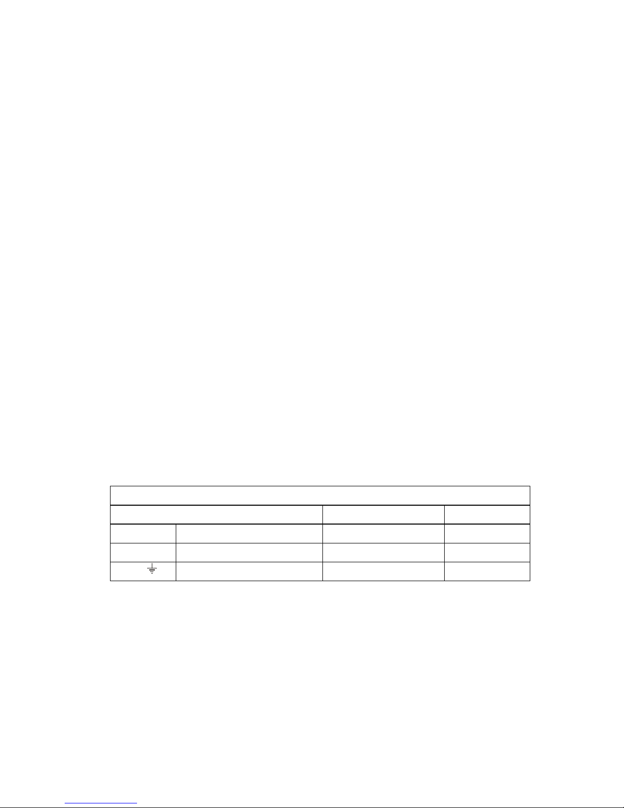
Please refer to the table below to connect a mains plug:
OVERVIEW: POWER CORD FUNCTION AND COLORS
CONDUCTOR COLOR Alternativ
LLIVE BROWN BLACK
NNEUTRAL BLUE WHITE
E PROTECTIVE EARTH GREEN+YELLOW GREEN
U.K. Mains Plug Warning:
A moulded mains plug that has been cut off from the cord is unsafe. Discard the mains
plug at a suitable disposal facility.
NEVER UNDER ANY CIRCUMSTANCES SHOULD YOU INSERT A DAMAGED OR
CUT MAINS PLUG INTO A 13 AMP POWER SOCKET. Do not use the mains plug
without the fuse cover in place. Replacement fuse covers can be obtained from your local
retailer. Replacement fuses are 13 amps and MUST be ASTA approved to BS 1362.

6
Mains Fuse:
The mains fuse of this appliance is soldered in place and accessible from the
inside only!!
A blown fuse may indicate an internal problem and should be replaced during
qualified servicing or repair work !!
Switchable Power Supply:
Connect this unit to the power source indicated on the equipment rear panel
only to ensure safe operation !!
This unit is provided with an internally settable mains supply for 115 / 230 V AC.
Service / Repair:
To reduce the risk of fire or electric shock, the user should not attempt to service the
appliance beyond the measures described in the operating manual. All other
servicing or repair should be referred to qualified personnel !!
Electromagnetic Compatibility
This unit conforms to the Product Specifications noted as Declaration of
Conformity at the end of this manual. Operation is subject to the following
conditions:
- this device may not cause harmful interferences
- this device must accept any interference received,
including interference that may cause undesired operation
- this device must not be operated within significant electromagnetic field
VOR DEM ÖFFNEN NETZSTECKER
ZIEHEN!! PULL MAINS BEFORE
OPENING!! AVANT D´OUVRIER
RETIREZ LA FICHE MALE!!

7
The Earth / Grounding Concept
General GROUND-LIFT Jumper (accessible from the inside.
Mind the SECURITY INSTRUCTIONS !! ):
Ex-works this jumper is set to the LIFT position.
The internal ground potential is “lifted” by means of this jumper.
As a result, the interconnection for DC voltages and lower frequencies
(< 150 Hz) will be cut. Higher frequencies will be bled off to earth
potential through the RC filter. The LIFT position is helpful in case of
hum or jitter caused by different ground/earth potentials.
Of coarse full electrical protection is garanteed as the case is always
connected to ground/earth potential !
See page 28 "Technical Appendix" for details.

8
Unfortunately there is no general recommendation how to solve hum
and jitter problems - or even minimize them. The best way to succeed is
to check different options !! In case of balanced cables, it should always
been verified if the shield of the cable is connected to the shell of the
XLR connector. The shell is ALWAYS connected to earth potential when
the connector is inserted !!
Concerning ANALOG inputs and outputs, the relationship between
ground and earth may be modified. Electrical safety is always ensured,
since the earth conductor is permanently connected to the enclosure !!
XLR GROUD-LIFT Jumper (accessible from the inside.
Mind the SECURITY INSTRUCTIONS !! ):
G(ROUND): Ex-works all jumpers are set to "G" (ground) position.
Pin 1 is connected to the internal ground reference.
High frequency interference is deflected to the case via a
100 nF capacitor.
L(IFT): The interconnection between Pin 1 and ground is open.
High frequency interference is deflected to the case via a
100 nF capacitor. This jumper position is specifically
useful if the unit is equipped with transformers !!
C(ASE): Pin 1 is connected to the case, the 100 nF capacitor is
bridged. This jumper position may be varied together with
the General GROUND-LIFT jumper.
Please note that with jumpers not in the ex-works position
EMC emission might occur,
for which the user is responsible only !

9
Connection / Connectors for Analog and Digital Signals

10
GENERAL INFORMATION
The HPA V181 is a stereophonic headphone amplifier designed to drive
low-, medium- and high-Z loads (16...600 ohms) as usually represented
by high-quality headphones.
V181 contains four amplifiers (2 x stereo) to enable proper driving of
balanced headphones.
Due to its specific, variable and low-noise and distortion circuit design
especially optimised for dynamic headphones, the HPA V181 fulfils
even highest demands.
Features:
- Balanced inputs with gold-plated Neutrik XLR connectors
- Unbalanced inputs with gold-plated ALPS cinch connectors
- switchable unbalanced outputs with cinch connectors
- PRE-GAIN = switchable input gain in five steps
- Independent-channel design
- DC-coupled (switchable)
- ALPS RK27 High-Grade volume control
- High-Quality op-amps in the signal path
- High-quality MKP capacitors in the signal path
- 0.1 and 1% metal film resistors throughout the unit
- 4 amplifiers with BUF634
- 1 balanced headphone output, Neutrik 4-pin, gold plated
- 2 silver-plated Neutrik headphone outputs
- Relay-based headphone output cutoff
- Toroidal transformer
- Large filtering capacitors in the power supply
- Switchable ground lift
- Rugged aluminium case with Nextel coating
- Solid, laser-engraved aluminium front panel
The HPA V181 is equipped with internal filters to prevent damage to the
connected headphones due to high-frequency overload beyond the
audible range.

11
THE CASE
The HPA V181's case as well as the front/rear panels are made of solid
aluminium. This choice of material ensures high mechanical stability and
resistance.
EARTH AND GROUND
The HPA V181's case is grounded. Internal reference ground is bridged
to protective earth by means of a jumper. If required, the jumper can be
set to 'LIFT' position (see also: page 7 "Earth/Ground concept", page
28 "Technical Appendix").
POWER SUPPLY
Mains power is provided via a three-pin IEC/CEE socket and mating
"cold-appliance" mains cord with Schuko-type plug. The device is set to
115 or 230V mains internally, whereas the actual voltage may vary
between 190 … 240 volts (85 … 120 volts for 115 V operation) for
flawless operation. A toroidal transformer provides the internal stabilized
operating voltages of +/- 18V .
MAINS FUSE
The 0.25A time-lag fuse is soldered in place on the circuit board. In
case, it must be replaced with a fuse of the same type only.
CAUTION !!
MIND THE SAFETY INSTRUCTIONS:
A blown fuse indicates an internal fault and
should be replaced during qualified repair or
servicing only !!

12
BALANCED SIGNAL INPUTS
The balanced signal inputs are situated on the rear panel of the unit and
are labelled as "BAL IN LEFT" and "BAL IN RIGHT". They are fitted with
XLR sockets.
Please note:
Unbalanced signals can be injected as well by means of an adaptor.
Also see page 9.
Balanced XLR pinout:
PIN 1 GND
PIN 2 (+) PHASE
PIN 3 (-) PHASE
UNBALANCED INPUTS
For the use with unbalanced signals, cinch sockets are provided. They
are labelled as "IN/OUT LEFT" and "IN/OUT RIGHT", and can be
configured as either inputs or outputs.
(about their configuration, see page 28)

13
Cinch sockets as inputs:
The cinch sockets are factory-preset as inputs and are equipped with
integrated switch contacts !
When a cinch plug is inserted, it cuts possible signals applied to the
balanced input automatically. I.e. the cinch input has priority.
Input impedance for all inputs is 10 kohms.
Maximum input level should not exceed +21 dBu.
This value is reduced to +15/+9 dBu if PRE-GAIN is set to +6/+12 dB !!
Cinch socket as outputs:
The cinch sockets can also be operated as outputs. This offers the
possibility of using a refreshed balanced or USB input signal for further
purposes.
Output levels equal the levels applied to the inputs, i.e. the signal is
amplified by 0dB (unity gain) at an output impedance of < 30 ohms.
See also page 28 "Technical Appendix"
THE OPTIONAL DIGITAL INPUT
Your headphone amp may be equipped with an optional DA converter
with one out of 3 different digital inputs.
The COAX input is made for digital PCM audio data coded as S/P-DIF
with a sample rate between 28 … 108 kHz.

14
The OPTO input is made according to the TOS-Link standard and is
waiting for digital PCM audio data with a sample rate between 28 … 108
kHz.
The USB type-B inputs on can be used to connect a host computer
(desktop or laptop PC). The headphone amp will be automatically
detected as an audio device. The USB input is 1.1- and 2.0-compatible.
Audio files stored on the host can be sent to the headphone amp,
whereas audio formats 24 bit with 44.1, 48 or 96 kHz are supported.
All digital modules are offering a DA converter offering 110 dB dynamic
range and –100 dB THD+N. Thus representing an upper-middleclass
solution.
Please note:
- The digital input has priority over all other inputs and will mute these
when a valif digital signal is detected
- When a USB cable is inserted, it may be required to restart running
media applications on the host.
- Volume control of the host application should be set to 100%.
Too loud ? Too soft ? The PRE-GAIN method
The V181 is specially designed to drive headphones. Headphones
however can present load impedances from 8 to 2000 ohms and
efficiency ratios from 85 to 115dB per milliwatt. Thus it can be quite
tricky to fulfil all demands, since...
… owners of high-effectivity headphones will rarely set the volume
control higher than 9 o'clock in order to exclude hearing damage, while

15
... the maximum setting may still be too soft for low-efficiency
headphones, but
… all users expect highest quality at lowest noise and distortion.
Thus, the circuitry must adapt itself as the headphone won't !
WE CALL THE SOLUTION TO THIS PROBLEM PRE-GAIN
The alignment between amplifier and headphone is provided by the
preamp stage, which can boost or attenuate the input signal in four
steps of 6dB each. For this purpose, two switching devices are located
on the rear panel for left and right channel individually.
CAUTION !!
The switch settings should be altered under the following conditions
only:
- The unit must be switched OFF
- the "VOLUME" control must be set to minimum
- left and right channel should ALWAYS be set the same
- never increase the setting by more than ONE step per
channel at a time.
If you find your HPA V181's volume could be somewhat softer (in order
to improve volume control range e.g.), push the switch labelled "-6dB"
(half gain) or "-12dB" (quarter gain) in upward direction.

16
If you find your HPA V181 should provide more gain, do so with the
switch labelled "+6 dB" (double gain) or "+12 dB" (quadruple gain).
Ex-factory, all switches are set to their lowest position - i.e. 0 dB or unity
gain - which should be sufficient for most applications.
OPERATION
Most control elements and indicators are located on the front panel.
POWER SWITCH
The unit is put into operation by means of the power switch. Power-on
status is indicated by the blue LED below.
VOLUME CONTROL
The "VOLUME" control sets the desired output volumes for left and right
channel simultaneously.
THE AMPLIFIERS
The input signals are fed to a special stereo amplifier which is equipped
equipped with 2 power stages per channel to generate balanced
signals. It has been designed for this application exclusively.

17
The individual-channel design provides optimum crosstalk rejection.
The amplifier's frequency range stretches from DC to over 200kHz
(-3dB cutoff frequency) in order to obtain absolutely linear character-
istics within the audible range. Overall gain is set to +8 dB in order to
provide sufficient reserves also for high-impedance headphones.
THE BALANCED HEADPHONE OUTPUT
The HPA V181 offers a balanced headphone output.
This is equipped with a gold plated female 4-pin XLR connector.
Balanced Headphone socket pinout:
Pin 1 (+) Left channel
Pin 2 (-) Left channel
Pin 3 (+) Right channel
Pin 4 (-) Right channel
THE UNBALANCED HEADPHONE OUTPUTS
The HPA V181 offers two stereophonic headphone outputs, each
equipped with a 1/4" (6.3mm) jack socket.
Unbalanced Headphone socket pinout:
TIP Left channel
RING Right channel
SLEEVE GND

18
Please note: the RIGHT phone jack is connected to the in-phase stereo
signal, whereas the left phone jack is connected to the 1800phase
shifted signal.
On power-up and power-down, the outputs are cut from the amplifier
circuitry by relay.
ALTERNATIVE BALANCED HEADPHONE CONNECTION
The phone jacks sockets of HPA V181 may be configured by means of
internal jumpers to provide balanced operation with two phone jack. To
configure the the sockets please refer to page 29 technical Appendix".
Left phone jack socket Right phone jack socket
TIP (-) left channel TIP (-) right channel
RING (+) left channel RING (+) lright channel
SLEEVE Ground (not necessary) SLEEVE Ground (not necessary)
HINTS FOR THE BALANCED OPERATION OF
HEADPHONES
As there is no common standard about how to make the connectors of
balanced headphones and headphone amplifiers, we decided to equip
our unit(s) with 4-pin XLR connectors.
In contrary to most XLR standards the female socket is situated on the
amp.
If you are not familiar in altering your headphones with matching
connectors we offer this work as a service. Please ask !!
ATTENTION:
Your headphone is double as loud as normal in balanced mode !!!

19
Things to know …
The HPA V181 offers balanced and unbalanced inputs.
Which advantages do balanced signals offer ?
In contrast to unbalanced signals, balanced signals are carried by two
wires (plus ground/shield). In the transmitting device, a balanced signal is
created by generating an inverted original signal (180ˆphase shifted). The
"hot" wire carries the original signal (a), the "cold" wire the inverted signal
(-a). In the receiving device, the balanced signal is processed by a
differential amplifier, which detects the difference between both: (a) – (-a)
= 2a.
On its way between devices, the useful signal can be affected by
interference (s). Interferences however are in phase on both wires and
fed to the differential amplifier as well. Again, the amplifier detects the
difference between the interference contents: (s) – (s) = 0. Thus - in an
ideal situation - all interference on the signal path is eliminated.
Like mentioned above, the balanced signals are fed to differential
amplifiers. From there - now being unbalanced - they get to the
switching contacts of the cinch inputs. If a plug is inserted here, any
balanced input signal possibly present is interrupted. I.e. unbalanced
signals fed to the cinch inputs have priority.
These signals are fed to buffer amplifiers - for left and right channel
separately - which also provide the PRE-GAIN setting.
Why are discrete signal paths important ?
Twin op-amps are the most common design for operational amplifiers,
i.e. two amplifier circuits are integrated in one device. If left- and right-
channel signals are processed simultaneously by such a device,
interaction between both cannot be excluded. This interaction is
admittedly diminutive, but should be avoided whenever a different design
offers the possibility.

20
Why are op-amps ideal for low-level signal processing ?
Discrete amplifiers (designed with transistors) are very popular in high-
end audio design also for preamplifier stages. This is often marketed as
an optimization measure, but the partially exorbitant extra expenses are
of course to be paid by the customer. But an op-amp consists of
transistors as well...
Moreover, its structure has the advantage of thermal coupling between its
internal components. Also ageing issues play a much less important role.
Due to the large number of op-amps types offered, it is possible to pick
an optimum type for any specific application.
Why does PRE-GAIN make sense ?
Two extreme examples (with the HPA V181 at 8dB gain, volume control
set to full cw):
1st example:
The (pre-)amplifier provides 4V output voltage, whereas the headphone
requires only 2V for 100dB sound pressure level.
With the control fully turned up, the V181 would deliver 10V output at 8dB
gain. Therefore the volume control would have to be operated very
carefully in order to avoid hearing damage. Moreover, any interference at
the input should be avoided since it would be "unforgivingly" amplified as
well. With PRE-GAIN, the input level can be reduced by 12dB (a fourth),
with 1V instead of 4V as the result. This 1V is again amplified by 2.5, then
equalling 2.5V. Now the volume control can be turned over almost the
entire range.
2nd example::
The (pre-)amplifier provides 1V, whereas the headphone requires 20V to
release 100dB of sound pressure.
With the volume control fully clockwise, the V181 would provide 2.5V at
8dB gain only - much to low for the headphone. By means of PRE-GAIN,
input level can be boosted by 12dB (four times), resulting in effective 4V.
These are again multiplied by 2.5, now equalling 10V. This is still not
enough, but far closer to the optimum value: The headphone achieves
114dB sound pressure level.
Table of contents
Other Violectric Amplifier manuals

Violectric
Violectric DHA V226 User manual

Violectric
Violectric HPA V200 User manual

Violectric
Violectric HPA V 100 User manual

Violectric
Violectric HPA V280 User manual

Violectric
Violectric HPA V90 User manual

Violectric
Violectric HPA V550 How to use

Violectric
Violectric HPA V550 PRO User manual

Violectric
Violectric PRE V630 User manual

Violectric
Violectric PPA V600 User manual

Violectric
Violectric HPA V281 User manual