Violectric PPA V600 User manual

1
PHONO PRE-AMPLIFIER
PPA V600
USER´s MANUAL

2
Content
Theme Page
About Violectric 3
Safety Instructions 5
The Earth / Grounding Concept 7
Connection / Connectors 9
General 10
Operation 11
Input Impedances 15
Input Capacities 16
Setting the Equalizer 17
Opening the Case / Dismantling 20
Things to know 21
Disposal 24
Technical Data 25
Jumper Setting 26
Conformity Statement 27
Warranty 28

3
Cordial thanks for your decision in favour of a
product !
is a trademark and product line of Lake People
electronic GmbH. Lake People electronic GmbH develops,
manufactures and distributes products in the professional range, for
broadcast, television, airports, exhibition halls, festival venues, theatres,
large-scale installations, private studios and more. In the private sector
as well, Lake People products become increasingly popular due to their
outstanding quality.
The trademark and product line is specially intended to
supply the Hi-Fi and High-End market with its specific requirements.
Who develops equipment ?
devices are exclusively developed in Germany by the
engineers of Lake People electronic GmbH. In doing so, the team of
developers can draw on twenty years of experience and countless
products for the pro-audio domain.
Among others, the first German-made 20-bit A/D and D/A converters
were developed by Lake People in the early nineties of the past century.
Who manufactures equipment ?
devices are exclusively manufactured in Germany by
Lake People electronic GmbH or contractors in the company's vicinity.
Lake People - and by association - put high emphasis
on domestic manufacturing. As well, all component suppliers are chosen
in order achieve the main part of added value inland.

4
How do devices get to the customer ?
devices can be obtained from respective specialist
suppliers. If there is none such accessible regionally, the customer is
supported by transregional distribution partners (google may help...)
and, of course, by Lake People electronic GmbH themselves.
… and if it doesn't work like it should ?
devices are covered by a 24-month warranty. In case of
any malfunction during this period, they can be shipped to the
manufacturer directly. Of course, the client will benefit from
's and Lake People's full technical support even when
warranty has expired. Any technical questions or need for advice is
welcome.
is a subsidiary of
LAKE PEOPLE electronic GmbH
Turmstrasse 7a
D-78467 Konstanz
Fon +49 (0) 7531 73678
Fax +49 (0) 7531 74998
www.violectric.de www.violectric.com
www.lake-people.de www.lake-people.com

5
General Safety Instructions
WARNING
For your protection, please read the following:
Water, Liquids, Moisture:
This appliance should not be used near water or other sources of liquids.
Care should be taken so that objects do not fall and liquids are not spilled into
the enclosure through openings.
Power Sources:
The appliance should be connected to a power supply only of the type described
in the operating instructions or as marked on the appliance.
Grounding:
Care should be taken that this appliance is operated with proper grounding only.
Power Cord:
Power supply cords should be routed so that they are not likely to be walked on
or pinched by items placed upon or against them, paying particular attention to
cords at plugs, convenience receptacles, and the point where they exit from the
appliance.
This unit is equipped with a 3-pole mains cable with German 3-pin mains plug.
In some countries this unit must be operated with a mains adaptor, supplied by
the owner.
Please refer to the table below to connect a mains plug:
OVERVIEW: POWER CORD FUNCTION AND COLORS
CONDUCTOR COLOR Alternativ
LLIVE BROWN BLACK
NNEUTRAL BLUE WHITE
E PROTECTIVE EARTH GREEN+YELLOW GREEN
U.K. Mains Plug Warning:
A moulded mains plug that has been cut off from the cord is unsafe. Discard the mains
plug at a suitable disposal facility.
NEVER UNDER ANY CIRCUMSTANCES SHOULD YOU INSERT A DAMAGED OR
CUT MAINS PLUG INTO A 13 AMP POWER SOCKET. Do not use the mains plug
without the fuse cover in place. Replacement fuse covers can be obtained from your local
retailer. Replacement fuses are 13 amps and MUST be ASTA approved to BS 1362.

6
Mains Fuse:
The mains fuse of this appliance is soldered in place and accessible
from the inside only!!
A blown fuse may indicate an internal problem and should be replaced
during qualified servicing or repair work !!
Power Supply:
Connect this unit to the power source indicated on the equipment rear
panel only to ensure safe operation !!
This unit is provided with a multi-mode switch-mode supply and accepts
mains voltages from 90 … 250 V AC and thus is suitable for glueless
worldwide operation.
Service / Repair:
To reduce the risk of fire or electric shock, the user should not attempt to
service the appliance beyond the measures described in the operating
manual. All other servicing or repair should be referred to qualified
personnel !!
Electromagnetic Compatibility
This unit conforms to the Product Specifications noted as Declaration
of Conformity at the end of this manual. Operation is subject to the
following conditions:
- this device may not cause harmful interferences
- this device must accept any interference received,
including interference that may cause undesired operation
- this device must not be operated within significant electromagnetic
field
VOR DEM ÖFFNEN NETZSTECKER
ZIEHEN!! PULL MAINS BEFORE
OPENING!! AVANT D´OUVRIER
RETIREZ LA FICHE MALE!!

7
The Earth / Grounding Concept
General GROUND-LIFT Jumper (accessible from the inside.
Mind the SECURITY INSTRUCTIONS !! ):
Ex-works this jumper is set to the LIFT position.
The internal ground potential is “lifted” by means of this jumper.
As a result, the interconnection for DC voltages and lower frequencies
(< 150 Hz) will be cut. Higher frequencies will be bled off to earth
potential through the RC filter. The LIFT position is helpful in case of
hum or jitter caused by different ground/earth potentials.
Of coarse full electrical protection is garanteed as the case is always
connected to ground/earth potential!
See also: page 20 / 26, Technical Appendix.

8
Unfortunately there is no general recommendation how to solve hum
and jitter problems - or even minimize them. The best way to succeed is
to check different options !! In case of balanced cables, it should always
been verified if the shield of the cable is connected to the shell of the
XLR connector. The shell is ALWAYS connected to earth potential when
the connector is inserted !!
Concerning ANALOG inputs and outputs, the relationship between
ground and earth may be modified. Electrical safety is always ensured,
since the earth conductor is permanently connected to the enclosure !!
XLR GROUD-LIFT Jumper (accessible from the inside.
Mind the SECURITY INSTRUCTIONS !! ):
G(ROUND): Ex-works all jumpers are set to "G" (ground) position.
Pin 1 is connected to the internal ground reference.
High frequency interference is deflected to the case via a
100 nF capacitor.
L(IFT): The interconnection between Pin 1 and ground is open.
High frequency interference is deflected to the case via a
100 nF capacitor. This jumper position is specifically
useful if the unit is equipped with transformers !!
C(ASE): Pin 1 is connected to the case, the 100 nF capacitor is
bridged. This jumper position may be varied together with
the General GROUND-LIFT jumper.
See also: page 20 / 26, Technical Appendix.
Please note that with jumpers not in the ex-works position
EMC emission might occur,
for which the user is responsible only !

9
Connection / Connectors for analog signals

10
GENERAL INFORMATION
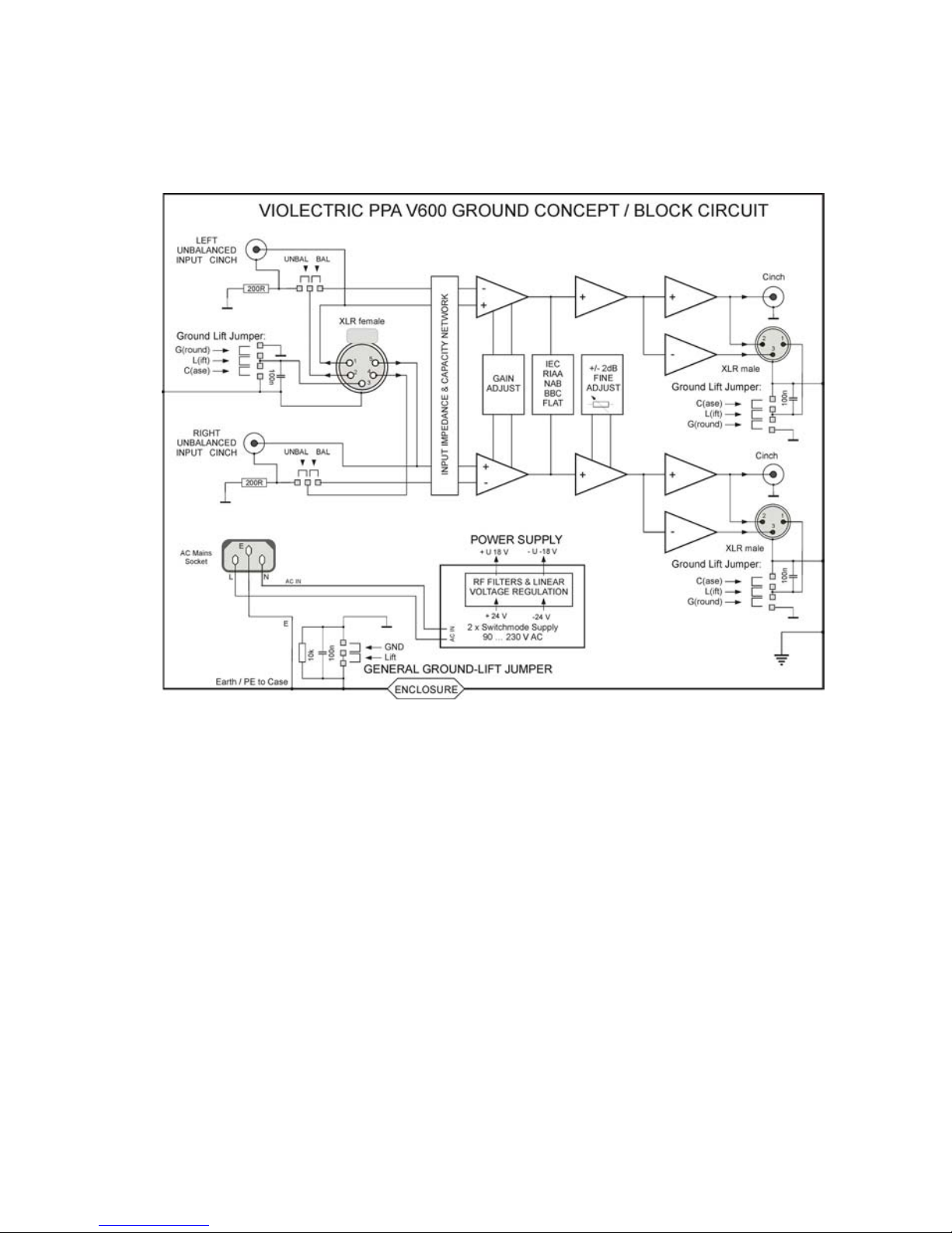
The PPA V600 is a high-quality, two-channel preamplifier for moving-
coil and moving-magnet pickup systems.
Its groundbreaking design allows a variety of setting possibilities second
to none. Due to the implementation of professional instrumentation
amplifiers in the input section, it offers extraordinarily low noise figures
and extreme bandwidth even at high gain.
Features:
- balanced inputs via gold-plated Neutrik 5-pin XLR sockets
- unbalanced inputs via gold-plated cinch sockets
- input impedance internally switchable, 9 settings
- input capacitance internally switchable, 16 settings
- low-noise instrumentation amplifier of extreme bandwidth
- front-switchable gain, in six steps from +36 to +60 dB
- front-face balance control +/- 2 dB
- internally selectable equalization: RIAA / NAB / BBC / FLAT
- internally switchable 20Hz high-pass according to IEC specifications
- individual-channel layout
- DC-coupled signal path
- top-grade operational amplifiers within the signal path
- high-quality MKP capacitors within the signal path
- 0.1 and 1% metal film resistors exclusively
- <0.05 dB aberration from RIAA curve due to eight reference points
- unbalanced outputs via gold-plated cinch sockets
- balanced outputs via gold-plated Neutrik XLR connectors
- lowest-noise and lowest-ripple switched-mode supply
combined with and precision linear-regulated powering
- internally switchable ground lift
- rugged aluminium case with Nextel coating
- solid aluminium laser-engraved front panel

11
THE CASE
The PPA V600's case as well as the front/rear panels are made of solid
aluminium. This choice of material ensures high mechanical stability and
resistance.
EARTH AND GROUND
The PPA V600's case is grounded. Internal reference ground is bridged
to protective earth by means of a jumper. The jumper is set to the 'LIFT'
position (see also: page 7 "Earth/Ground concept" and pages 20/26
"Technical Appendix").
POWER SUPPLY
Mains power is provided via a three-pin IEC/CEE socket and mating
"cold-appliance" mains cord with Schuko-type plug. Because of the
employed multi-mode switch-mode supply the actual AC voltage may
vary between 90 and 250 volts AC for flawless operation.
The US and Japan version comes with a US style mains cord.
Bith switch-mode supplies will output 24 V DC. External filters will cut
any high frequency glitches. Line regulators form the internal operating
voltages of +/-18 V.
MAINS FUSE
The 0.25A time-lag fuse is soldered in place on the circuit board. In
case, it must be replaced with a fuse of the same type only.
CAUTION !!
MIND THE SAFETY INSTRUCTIONS:
A blown fuse indicates an internal fault and
should be replaced during qualified repair or
servicing only !!

12
THE BALANCED SIGNAL INPUT
For the connection of balanced signals a gold-plated 5-pin XLR socket
is located in the 'cartridge input' section on the rear of the unit, denoted
as 'BAL'.
5-pin XLR Pin-Out:
PIN 1 Left (+) PHASE
PIN 2 Left (-) PHASE
PIN 3 Ground
PIN 4 Right (-) PHASE
PIN 5 Right (+) PHASE
THE UNBALANCED INPUTS
Or the connection of unbalanced signals two gold-plated cinch sockets
are located in the 'cartridge input' section, denoted as 'UNBAL L' and
'UNBAL R'.
INPUT SELECTION
The cinch inputs sockets are activated ex-works.
In order to utilize the balanced inputs, the unit must be opened and the
two related jumpers set from 'U' (unbalanced) to 'B' (balanced).
See also: technical appendix page 20 / 26.

13
OPERATION
The following controls and displays are located on the front panel:
POWER SWITCH
The unit is turned on by means of the power switch. The blue LED
beneath the switch indicates that the unit is ready for operation.
GAIN SWITCH
The gain switch on the front panel allows easy signal gain control,
offering six possible settings: 30 / 36 / 42 / 48 / 54 and 60 dB. Gain is
set for both channels individually by means of a precision resistor array,
thus offering highly accurate stereo matching at lowest crosstalk.
Settings of 30...42 dB are usually suited for MM systems, while 48...60
dB are intended for the use with MC pickups. So-called 'high output MC'
systems are best operated at 42...48 dB gain.
As noise level rises proportional to gain, it is always recommended to
choose the lowest practical gain setting !
BALANCE CONTROL
By technical means, pickup systems usually don't present exact channel
balance, and even sophisticated systems can exhibit a channel
matching error of 1...2 dB. This can lead to a shifted stereo image

14
which, however, can easily be compensated by the balance control, with
an adjustment range of +/-2 dB and a detented centre position.
In order to maintain minimum crosstalk, balance is set by means of fine
adjustment of the right channel, instead of a conventional balance pot
as found on other devices.
AMPLIFIERS / INTERNAL SETTINGS
The low input signals are fed to a so-called instrumentation amplifier,
originally intended for the use with professional microphones. This
allows extremely low-noise amplification vastly superior to any other
design, while offering an internal bandwidth of >200 kHz even at 60 dB
gain.
Susceptibility to hum as induced by low-frequency equalization and
interference to the cable between turntable and input can be
significantly reduced by balanced coupling between the pickup system
and the amplifier, using balanced cabling.
In order to precisely match with any pickup model, 9 input impedance
and 16 input capacitance settings can be selected by DIP switches
inside the unit.
While the RIAA equalization curve is the most commonly used, the PPA
V600 can also be switched to NAB, BBC or FLAT curve. In addition, it
provides a 20Hz IEC high-pass filter, which can be inserted in the signal
path by DIP switches. All the filters are passive designs, using high-
quality and non-ageing MKP capacitors. By means of eight reference
points, the RIAA curve is precisely maintained with an accuracy of 0,05
dB.
Channel circuits are completely separate, in order to obtain optimum
crosstalk rejection.

15
INPUT IMPEDANCE
Input impedance can be precisely matched to the respective MC
(moving-coil) system by means of switchable input impedance. The
value matching best can either be read in the pickup's technical
specifications, or optimized by further recommendations and listening
tests.
Settings comprise 10, 90, 100, 130, 150, 250, 330, 1k and 47k ohms,
whereas 47k is recommended for MM (moving magnet) systems. The
unit's case must be opened to change this setting.
See also: technical appendix, pages 20 / 26.
The DIP-switches marked with “MC” may be set as follows:
Note: Setting ex works is 47kOhm

16
INPUT CAPACITANCE
Input capacitance can be precisely matched to the respective MM
(moving magnet) system by means of switchable input capacitance. The
value matching best can either be read in the pickup's technical
specifications, or optimized by further recommendations and listening
tests.
Settings comprise 33, 66, 110, 150, 180, 210, 260, 300, 330, 370, 410,
450, 480, 520, 560 and 600 pF.
Input impedance for MM systems should be set to 47k ohms !
The unit's case must be opened to change this setting.
See also: technical appendix, pages 20 / 26.
The DIP-switches marked with “MM” may be set as follows:
Note: Setting ex works is 33 pF

17
EQUALIZATION CURVES

18
EQUALIZATION CURVES
Due to technical considerations, the signal stored on vinyl records has
been equalized during manufacture, i.e. low frequencies are reduced
and high frequencies are boosted. Upon playback in turn, an equalizer
as accurate as possible is employed in order to re-linearize frequency
response. There were several dozens of equalization curves in record
history, but fortunately the so-called RIAA curve (Recording Industry
Association of America) has established itself as the most common
standard. Nevertheless, one may encounter records manufactured
using NAB (National Association of Broadcasters), BBC (British Broad-
casting Corporation) or FLAT (no treble EQ) equalization curves, which
the V600 can easily cope with by means of its switching capabilities.
Furthermore, a 20 Hz highpass or 'rumble' filter according to IEC
(International Electrotechnical Commission) can be switched into circuit.
See also: technical appendix, pages 20 / 26.
Note: Setting ex works is RIAA

19
THE UNBALANCED OUTPUTS
The unbalanced output signal is available at gold-plated cinch sockets
on the rear panel. They are denoted as 'UNBAL L' for the left channel,
and 'UNBAL R' for the right one respectively.
Output impedance is significantly less than 1 ohm !
THE BALANCED OUTPUTS
The balanced output signal is available at gold-plated XLR connectors
on the rear panel. They are denoted as 'BAL L' for the left channel, and
'BAL R' for the right channel respectively.
Output impedance is significantly less than 1 ohm !
Output polarity complies with AES 14-1992:
1 = ground / 2 = in phase / 3 = out of phase.
NOTE:
When connecting unbalanced loads to the balanced outputs, pin 3 must
not be bridged to signal ground but left unconnected. Output signal level
drops by 6 dB in this mode.
NOTE:
Unbalanced and balanced outputs shall not be used simultaneously, as
the output driver feeds both the cinch socket and the in-phase pin of the
balanced output at the same time.

20
OPENING THE UNIT
In order to change any DIP switch or jumper settings inside the PPA
V600, its case must be opened. For this purpose, a TORX screwdriver
T10 is required, and you should - by all means -
PULL THE MAINS PLUG !!!
after which any setting procedures can be effected without risk.
Disassembly
1. remove the two upper screws on the front panel
2. loosen the two lower screws on the front panel by 2 to 3 turns
3. remove the two upper screws on the rear panel
4. lift off the lid to gain access to the switches/jumpers
5. reassemble the unit in reverse order.
Things to know…
Why are turntables susceptible to hum ?
Most turntables are connected unbalanced via cinch leads. Unfortunately
indeed, since a balanced connection would be hum-free in practice and much
more advisable in technical terms. Common pickup systems usually represent a
perfect dipole, and thus the advantages of balanced signal connection could
easily be made use of.
Moreover, vinyl recordings are being equalized during the production process,
i.e. low frequencies are reduced and high frequencies boosted. During playback,
the equalizing preamplifier inverts this process, thus enhancing not only the low
frequency range, but also any hum interference to the signal lead.
When connecting the pickup in balanced mode, hum interference as would be
unavoidable with unbalanced leads is significantly reduced.
Table of contents
Other Violectric Amplifier manuals

Violectric
Violectric PRE V630 User manual

Violectric
Violectric HPA V550 PRO User manual

Violectric
Violectric HPA V200 User manual

Violectric
Violectric HPA V 100 User manual

Violectric
Violectric DHA V226 User manual

Violectric
Violectric HPA V90 User manual

Violectric
Violectric HPA V281 User manual

Violectric
Violectric HPA V550 How to use

Violectric
Violectric HPA V181 User manual

Violectric
Violectric HPA V280 User manual