Virax 162120 User manual

Threading machine
for tubes up to 2”
Instruction Manual
162120
EN

EC DECLARATION OF CONFORMITY
VIRAX 39, Quai de Marne - B.P. 197 - 51206 ÉPERNAY Cedex - FRANCE
Declares that the machine described below
162120 VIRAX Workshop Threading machine ½ to 2”
Complies with the requirements of the following Directives:
2006/95/EC relating to electrical equipment designed for use within certain voltage limits. (Low voltage)
2004/108/EC "ElectroMagnetic Compatibility" relating to electromagnetic compatibility and repealing
Directive 89/336/EEC
98/37/EC relating to “machinery",
and to relevant national legislation transposing these directives.
Complies with harmonized European standards : EN 55014-1
EN 55022
Epernay August 24th, 2009.
Eric MIN 09
Quality Manager
889733 Anglais
EN

EN

162120 Threading Machine for tubes up to 2”
Instruction manual
Thank you for purchasing the threading machine and for showing condence in our company.
Virax, a major manufacturer and retailer of tools for the Sanitary, Environmental engineering and
Roong trades, supplies the tools you use in your everyday work:
Virax, showing off your talent.
This documentation has been produced with care to enable you to use the machine to
its best and in complete safety. We strongly recommend you to read this instruction
manual carefully before using the machine and to keep it within easy reach of the
machine.
EN

3
Sommaire
Safety instructions...................................................................................... 5
General safety instructions..................................................................................... 5
Choice of tool .................................................................................................................... 5
Maintenance and storage ................................................................................................. 5
Safety instructions for the user ......................................................................................... 5
Safety instructions relating to the work area ..................................................................... 6
Prohibited uses ...................................................................................................... 6
Handling and working instructions ......................................................................... 7
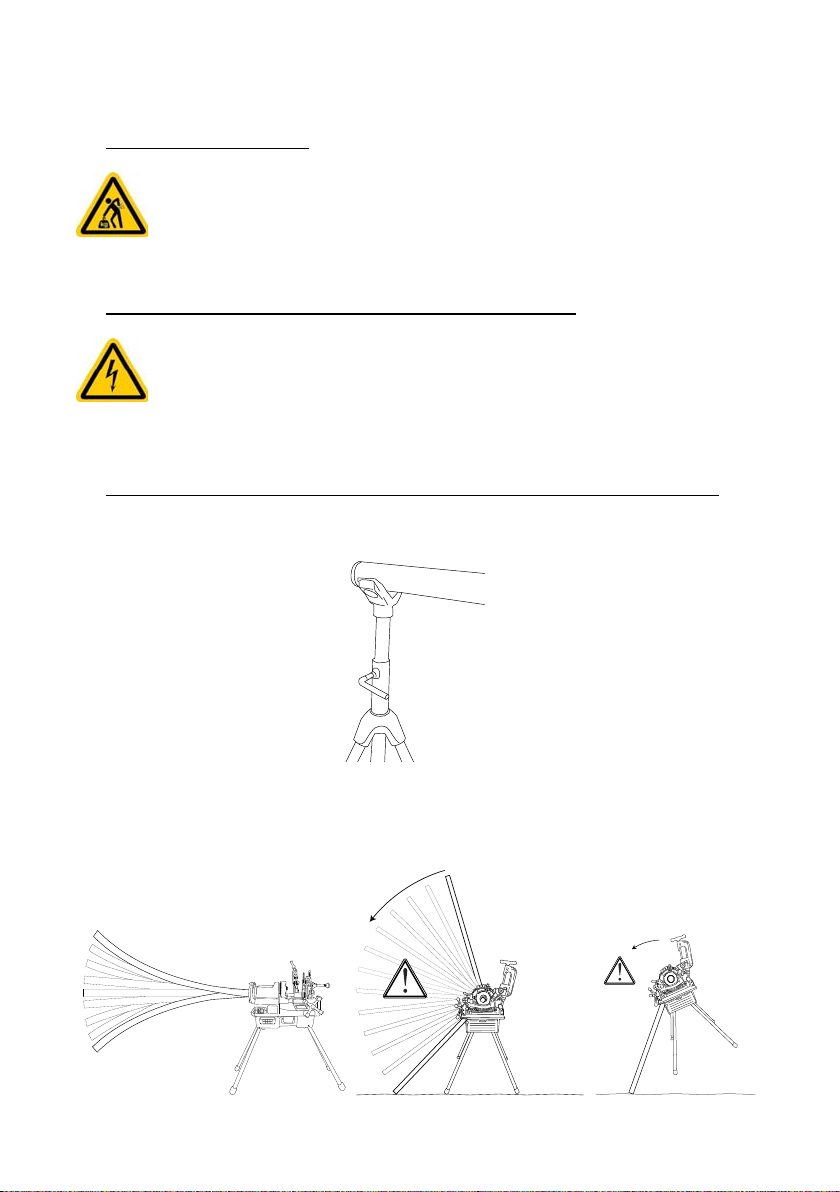
Transporting the machine ................................................................................................. 7
Instructions relating to the machine electrical power supply. ............................................ 7
Instructions relating to your protection and the protection of those around you ............... 7
Maintenance instructions .................................................................................................. 9
Storage instructions .......................................................................................................... 10
General description of the 162120 threading machine............................ 11
Basic functions ................................................................................................................. 11
Diameters of tubes which can be threaded ...................................................................... 11
Tubes which can be threaded, cut or reamed .................................................................. 11
Available thread types ...................................................................................................... 12
Setting the length and outside diameter of the thread ...................................................... 12
Option of installing a groover ............................................................................................ 12
General characteristics ..................................................................................................... 13
Moving and setting up the machine .......................................................... 14
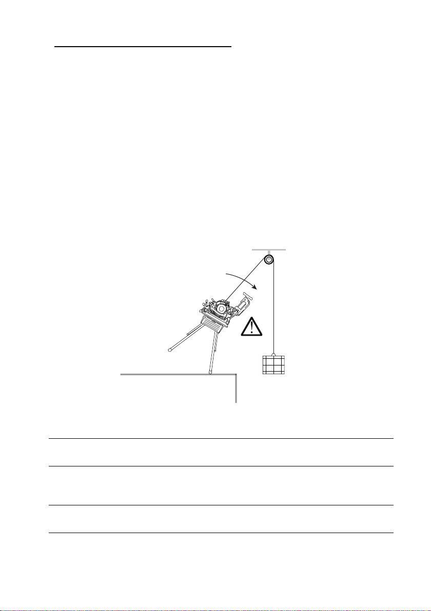
Moving by lifting equipment .............................................................................................. 14
Moving manually ............................................................................................................... 15
Moving using a trolley ....................................................................................................... 15
Slope of the machine ........................................................................................................ 17
Positioning a tube ....................................................................................... 18
Positioning short tubes ..................................................................................................... 18
Cutting a tube .............................................................................................. 19
Reaming a tube............................................................................................ 20
Threading a tube.......................................................................................... 21
Producing a thread ........................................................................................................... 21
Producing double threads on short tubes (nipples or reels) ............................................. 22
Using the 2” die head (Part no. 162151) ................................................................ 25
Installing the head ............................................................................................................ 25
Adjusting the threading diameter ..................................................................................... 26
Adjusting the thread outside diameter .............................................................................. 27
Adjusting the thread length ............................................................................................... 27
EN

4
Using the 1/4 – 3/8” head (part no. 162150) .......................................................... 28
Installing the head ............................................................................................................ 28
Adjusting the threading diameter ..................................................................................... 29
Adjusting the thread outside diameter .............................................................................. 29
Manually opening the dies ................................................................................................ 29
Replacing the dies.................................................................................................. 30
Replacing dies on the automatic opening 2” head ........................................................... 30
Replacing dies for the 1/4 – 3/8” head .............................................................................. 32
Maintenance operations ............................................................................. 34
Cleaning the oil system .......................................................................................... 34
Replacing the motor brushes ................................................................................. 35
Taking up shaft slack .............................................................................................. 36
Replacing the cutter wheel ..................................................................................... 36
Replacing the tube cutter ....................................................................................... 37
Replacing the reaming cone .................................................................................. 38
Replacing the reamer ............................................................................................. 38
Replacing the front chuck jaws .............................................................................. 39
Replacing the front chuck jaw holders ................................................................... 41
Diagnostics and fault xes......................................................................... 44
Machine operating problems .................................................................................. 44
Thread cutting problems ........................................................................................ 45
Tube cutting problems ............................................................................................ 47
Reaming problems ................................................................................................. 47
Exploded views............................................................................................ 48
Exploded view of the frame .................................................................................... 48
Exploded view of the motor and the oil pump ........................................................ 49
Exploded view of the transmission ......................................................................... 50
Exploded view of the saddle .................................................................................. 51
Exploded view of the automatic opening 2” die head............................................. 52
Exploded view of the 1/4” - 3/8” die head............................................................... 53
Exploded view of the tube cutter ............................................................................ 54
Exploded view of the reamer.................................................................................. 55
Components of a nipple holder .............................................................................. 56
EN

5
Safety instructions
The Virax 162120 threading machine is an electro-mechanical machine which presents certain
hazards. It is therefore important to obey the following instructions to avoid causing yourself or
others possible serious injuries or lesions.
General safety instructions
Choice of tool
Use a suitable tool. Do not use low-power adaptable tools or devices for carrying out heavy work.
Do not use tools for purposes other than those for which they have been designed.
Maintenance and storage
Store your tools in a safe place. Unused tools must be stored in a dry, closed location out of the
reach of children.
Maintain your tools carefully. Maintain your own tools so that you can work better and in greater
safety. Observe maintenance indications as well as those relating to the changing of accessories.
Keep handles dry and free of oil and grease.
Check whether the tool is damaged. Before using the tool, always carefully check that all the
parts are operating correctly. Check that the parts move correctly, that they do not seize and that
other parts are not damaged. All the components must be installed correctly and full the
conditions needed to ensure that the tool is in perfect working order. All safety devices, switches
or other damaged or defective parts must be appropriately repaired or replaced by a qualied
technician.
Warning! Be sure to use the tool and its accessories in accordance with the safety instructions.
Consider the range of options for the tool taking into account the working conditions and the task
to be carried out. It can be dangerous to use the tool for tasks for which it is not intended.
This tool complies with current safety regulations. All repairs must be carried out by qualied
professionals using original spare parts, failing which the tool may become dangerous to use
and the warranty will be nullied.
Safety instructions for the user
Keep children away. Do not allow other people to touch the tool; keep them away from your
working area.
Wear appropriate working clothes. Do not wear loose clothing or jewellery; they could be caught
in the moving parts.
When working in the open air, you are recommended to wear rubber gloves and shoes with
nonslip soles. If you have long hair, tie it back with a hair net.
Do not increase your range. Avoid adopting a posture which you nd tiring; make sure you have
a rm footing and always maintain your balance.
Always concentrate. Look at your work, use your common sense and do not use the tool when
you are tired.
–
–
–
–
–
–
–
–
–
–
–
EN

6
Safety instructions relating to the work area
Keep your work area tidy. Untidiness increases the risk of an accident.
Take into account the environment around your work area. Do not expose electric power tools to
the rain. Do not use electric power tools in a damp or wet environment.
Make sure the work area is well lit. Do not use electric power tools in the neighbourhood of
inammable liquids or gases.
Prohibited uses
The machine is not intended for tightening or loosening joints.
You may be tempted to use the power of the machine for tightening or loosening joints. Doing
this is prohibited as the force of the motor is much greater than the force exerted by the hand
holding the joint whether directly or using a spanner. When loosening, you risk fracturing your
hand or forearm or having the spanner thrown at you or one of your colleagues. (Moreover, when
loosening, if the joint has not been released, you will subject the motor to a force which may
damage it.)
The machine is not a winch.
You may be tempted to use the force of the motor to raise or lower loads. This use is prohibited
as the machine could topple over and jettison its load. (Moreover, you may damage the motor).
The machine is not intended for coating the threads with sealing paste.
As the paste is naturally applied by hand, this exposes the operator to the risk of being cut.
Important: Virax may in no respect be held liable for accidents which occur arising from the
machine being used for purposes other than those for which it was intended.
Do not use tools other than those designed for use with the machine.
Only the cutting, reaming and threading tools designed for the machine may be mounted on the
machine.
Important: Virax may in no respect be held liable for accidents which occur arising from the use
of tools other than those specically intended for use with the 162120.
–
–
–
–
–
–
–
EN

7
Handling and working instructions
Transporting the machine
The machine weighs about 60 kg. So two people are needed to carry it. Two handles
are provided at either end of the frame for this purpose.
To move the machine using a hoist or crane, proceed as indicated in page 14.
In addition, a trolley has been especially designed for transporting the machine.
(This is described on page 15).
–
Instructions relating to the machine electrical power supply.
The machine must be provided with a 230V electrical power supply.
The plug and any extension lead must have a grounding pin connected to a ground
connection in the workshop.
Do not pull the machine by its power cable. (This is not a rope!). Likewise, do not
disconnect the machine by pulling on the cable.
–
–
–
Instructions relating to your protection and the protection of those around you
It is essential to place the tube on one or more pipe holders, also called benches. (Virax part
numbers: pipe holder without feet: 161100 ; pipe holder with feet: 161110).
If the free length of the tube behind the machine is too long (typically more than 1m empty), you
risk the tube starting to oscillate (which you may not realize in time as your attention will be on
the tube being machined) which then causes the machine to become unstable causing it to
topple towards you.
–
EN

8
Do not wear a tie, scarf, pendants, loose clothing, chain bracelets, rings etc.
or wear your hair long... any of which could be caught by the rotating parts of the
machine.
–
Wearprotectivegoggles toprotectyour eyesfrom oilspatter and,most importantly,
from any metal turnings which are thrown up. In the case of oil spatter, wash your
eyes copiously with water and consult an ophthalmic doctor if you experience any
problems with your vision. If a metal turning is thrown up, do not try to remove it or
have it removed by anyone else but consult a specialist service immediately.
–
It is essential to wear a helmet with ear defenders.
In compliance with standard EN 61029-1 (refer to the standard published in your
language) and standard ISO 3744, laboratory tests have given the following
results:
Acoustic power level: LwA = 92 dB(A)
Acoustic pressure at the user’s ears: LpA = 84 dB(A)
LpMaxPeak < 130 db(C)
–
Be careful not to cut yourself on contact with sharp items, in particular: cutter
wheel, thread dies, reaming cone, internal edges of the tube.
–
Wear gloves for handling metal turnings: these can cause bad, ne and deep
cuts.
Wear gloves if you are allergic to lubrication oil.
–
–
Pay attention to crushing hazards, in particular when lowering the tube cutter, the
die head or the reamer and when the saddle is moving.
–
Wait for the motor to stop before carrying out any work.
Disconnect the machine when carrying out assembling, dismantling and cleaning
operations in order to guard against the risks of the machine being accidentally
started up: you or one of your work colleagues could accidentally step on the control
pedal or press the start button while your hands are in the machine.
Warning: The machine is protected against accidental starting by a relay. After the
electrical power is cut, you can only start the machine by pressing the start button.
You must not under any circumstances short circuit the start button under the
pretext of «helping you with your work».
Likewise, you must not use a machine whose start or stop button is not
working.
–
–
EN

9
Before starting the machine, check there are no tools (Allen key, screwdriver, open-
end wrench, etc.) on the machine: when the motor starts, the tool may be thrown
towards you or one of your colleagues.
Check that no unauthorized person is in the vicinity of the machine.
–
–
Stop the machine immediately if you notice anything unusual about the way it is
running: motor slowing down or stalling, sparks, smoke, burning smell, vibrations,
etc.
Refer to the “Diagnostic and fault xing” chapter in this manual. If the indications
given do not enable you to resolve the problem, contact Virax or one of its
representatives.
–
Do not work on the machine if you do not feel well: drowsiness, fever, feeling very
tired. Many accidents in the workplace are due to a lack of vigilance.
–
Maintenance instructions
Regularly check the state of the machine. Identify, as much as possible, any cracks, overlarge
play etc. and in general any anomaly.
Regularly change the four dies of the die head, especially when the turnings become less
whole and more broken up.
Regularly check the oil level. You must not thread your tubes without a sufcient oil ow.
You must use one of the oils supplied by Virax as all mechanical tests have been carried out
using these oils.
Oils which can be used:
Oil for cutting steel tubes
Possible packaging:
1 L drum (part no. 110101)
5 L drum (part no. 110105)
1 case of 12 x 1L drums (part no. 110112)
20 L drum (part no. 110120)
500 ml aerosol (part no. 110200)
Case of 12 x 500 ml aerosols (part no. 110202)
Oil for cutting stainless steel tubes
Possible packaging:
5 L drum (part no. 110505)
1 case of 4 x 1L drums (part no. 110506)
Synthetic cutting oil
Complies with sanitary standard DVGW (identication no. DW-0201AT2541).
Possible packaging:
5 L drum (part no. 110605)
Important: The warranty will be invalidated if any oil is used which has not been supplied by
Virax.
–
–
–
–
●
●
●
EN

10
Besides the tasks shown in the Maintenance chapter, you must not carry out dismantling and
assembly operations yourself. These operations must only be carried out by personnel
approved by Virax.
Important: Virax may not be held liable for accidents which occur as a result of an unauthorized
maintenance operation.
Storage instructions
Store the machine powered off in a dry place where there is no risk of water or dust spatter, and
cover it with a tarpaulin.
–
–
EN

11
General description of the 162120 threading machine
Basic functions
The 162120 threading machine carries out the following three functions:
cutting tubes
threading tubes by stock removal
reaming
Diameters of tubes which can be threaded
The die head supplied with the machine (part no. 162151) can be used to thread tubes with
diameters from 1/2” to 2”.
Optionally available is a manual die head (part no. 162150) which can be used to thread tubes with
diameters from 1/4” to 3/8”.
Tubes which can be threaded, cut or reamed
The tubes which can be used on the 162120 are dened by the following standards (refer to the
editions published in your language):
1. Stainless steel tubes
EN ISO 1127 June 1996
Stainless steel tubes - Dimensions, tolerances and conventional linear densities
EN 10216-5 March 2005
Seamless steel tubes operating under pressure - Technical delivery conditions
Part 5: Stainless steel tubes
EN 10217-7 August 2005
Welded steel tubes operating under pressure - Technical delivery conditions
Part 7: Stainless steel tubes
2. Carbon steel tubes:
EN 10208-2 October 1996
Steel tubes for carrying combustible uids - Technical delivery conditions
Part 2: Tubes of specication class B
EN 10216-1 December 2002
Seamless steel tubes operating under pressure - Technical delivery conditions
Part 1: Tubes in unalloyed steel with characteristics specied at ambient temperature
EN 10217-1 December 2002
Welded steel tubes operating under pressure - Technical delivery conditions
Part 1: Tubes in unalloyed steel with characteristics specied at ambient temperature
EN 10255 March 2005
Unalloyed weldable and threadable steel tubes - Technical delivery conditions
Important: not all tubes mentioned in standards prior to standard EN 10255 can be threaded.
Depending on diameter, the thicknesses must be greater than or equal to the thicknesses dened
by standard EN 10255.
–
–
–
EN

12
Available thread types
The machine can produce the following thread types:
with the 2” head
BSPT (British Standard Pipe Taper thread)
NPT (National standard taper Pipe Thread)
Metric
BSPP (British Standard Pipe Parallel)
BSW (British Standard Whitworth)
UNC (Unied National Coarse)
NPSM (National Pipe Straight Mechanical)
with the 3/8” head
BSPT
BSW
Note: The 2” head is tted with a BSPT + NPT scale as standard.
Setting the length and outside diameter of the thread
The heads allow the length and outside diameter of the thread to be set.
Option of installing a groover
In addition to the three basic functions (cutting, reaming, threading), the machine can be used with
a Virax groover (part no. 162400, available as an option) for hollow tubes in carbon steel with
diameters from 1 to 6” and maximum thickness of 3.4 to 5.5 mm in compliance with the standards
given on the previous page: EN 10208-2, EN 10216-1, EN 10217-1, EN 10255 W and S:
●
–
–
–
–
–
–
–
●
–
–
EN

13
General characteristics
Power: 1100 W
Rotational speed: 34 rpm
Weight of machine only, without mounting feet and without die head: 51.5 kg
Weight of feet: 6.2 kg
Weight of 2” die head: 6.6 kg
Overall dimensions of the machine on its feet
(length x width x height, in mm): 1170 x 705 x 1100
Acoustic power level: LwA = 92 dB(A)
Acoustic pressure at the user’s ears: LwA = 84 dB(A)
LpMaxPeak < 130 db(C)
Machine supplied with:
4 feet
1 x 5L drum of cutting oil for steel tubes
1 x 2” automatic die head
1 set of dies, 1/2” - 3/4”
1 set of dies, 1” - 2”
1 set of 2 carbon brushes
1 spare cutter wheel
●
●
●
●
●
–
–
–
–
–
–
–
EN

14
Moving and setting up the machine
There are three ways of moving the machine:
by a lifting device such as a hoist or winch
manually
on the Virax trolley especially designed for the 162120 threading machine (part no.
162160)
Important:
1) The oil tank must be drained before moving the machine any great distance.
2) Whatever method of transportation is used, the machine must always be transported with a
tube clamped between the chucks and the die head, the tube cutter lightly tightened against
the tube.
Moving by lifting equipment
Raise the die head (see pages 25 and 28 for the procedure for installing the various heads).
Warning: Do not forget to do this as the die head is simply xed to its shaft and
can therefore fall off during transport.
Use a 2” tube of sufcient length to overlap the two sides of the machine by about 30 cm.
Carefully ream each tube end to avoid the tube edges cutting the lifting cable (see page 20
for the reaming procedure).
Insert the tube into the machine and check that the ends leaving the machine are as equal in
length as possible and tighten both chucks. (See page 18 for instructions for mounting a
tube):
Place the tube cutter on the tube and tighten it so it is held rmly in place.
Pass the lifting cable through the tube and move the machine thus carried by the tube. (Once
the machine is suspended, you can, if necessary, unscrew the feet to facilitate transport):
–
–
–
●
●
●
●
●
●
EN

15
Moving manually
The machine has two transporting handles at each end:
Warning: Two people are needed to raise the machine. Raise and move the machine only by using
its handles. (The other parts of the machine do not give a secure grip).
Moving using a trolley
The folding trolley designed by Virax (part no. 162460) enables the 2” machine to be transported
and used without setting it back on its feet:
EN

16
To place the machine on its trolley:
Remove the retaining hook by depressing the handle using the foot, lift the handle until the
trolley is fully unfolded and lock the two retaining levers (levers turned downwards):
Placethemachineonitssupport,rear of the machine towards the handle, and x the retaining
screws provided with the trolley.
To transport the trolley with the machine and load it onto a lorry:
Drain the machine.
Unlock the two retaining levers (the gas cylinders are designed to support the weight of the
machine).
Lower the trolley handle, fold up the trolley completely, lock the retaining hook
(Warning: don’t forget to do this!) and transport the trolley holding it by its handle.
Place the front wheels on the edge of the lorry and raise the rear section of the trolley so as
to be able to load it fully into the lorry.
Warning:
1) Secure the machine rmly to its trolley using the screws supplied whether the machine is being
transported or used.
2) The trolley must not be used as a platform.
3) When loading the trolley-machine assembly remember to bend your legs and never lift
using the back.
4) When transporting on a lorry, remember to chock the trolley wheels.
●
●
●
●
●
●
Retaining
hook
Retaining
hook
Retaining leversRetaining levers
EN

17
Slope of the machine
The machine placed on the level on its feet or on its trolley slopes 2° to the front:
2 °
This slope prevents oil owing towards the back in the tube. Check therefore that this slope is
maintained where work is to be carried out.
Be careful to secure the feet rmly to avoid the machine falling.
EN

18
Positioning a tube
Open the two chucks sufciently.
Insert the tube from the rear, if the working conguration allows this, such that the end of the tube
to be machined is level with the tool to be used.
Centre the tube and tighten the chucks starting with the front chuck.
Note: The front chuck is a hammer chuck: strike several blows towards you (when you are on the
operator’s side) to tighten the jaws onto the tube.
To loosen the chuck, give successive blows in the opposite direction.
Positioning short tubes
Place the tube in the front chuck and tighten the chuck just so it holds the tube.
Lower the die head and move the saddle so that the dies come into contact with the tube
end:
Use the dies in the die head to centre the tube and tighten the front chuck.
●
●
●
●
●
●
EN
Table of contents
Other Virax Industrial Equipment manuals