LAUNCH TECH LAUNCH KWA-300 User manual

LAUNCH KWA-3003DWheelAligner
i
TrademarkInformation
LAUNCH isaregisteredtrademarkof LAUNCH
TECH. CO.,LTD. (LAUNCHforshort) inChinaand
other countries. All other LAUNCH trademarks,
service marks, domain names, logos, and company
names referred to in this manual are either
trademarks, registered trademarks, service marks,
domain names, logos, company namesof or are
otherwise the property of LAUNCH or its affiliates. In
countries where any of the LAUNCH trademarks,
service marks, domain names, logos and company
names are not registered, LAUNCH claims other
rights associated with unregistered trademarks,
service marks, domain names, logos, and company
names. Other products orcompanynames referred
to in this manual maybe trademarks of their
respective owners. You may not use any trademark,
service mark, domain name, logo, or company
name of LAUNCH or any third party without
permission from the owner of the applicable
trademark, servicemark, domain name, logo,or
company name. You may contact LAUNCH by
visiting Launch at http://www.cnlaunch.com,or
writing to LAUNCH, Xinyang Building, Bagua4th
Road, Shenzhen, Guangdong Province, P.R. C., to
request written permission to useMaterials onthis
manual for purposes orfor allother questions
relating to this manual.
CopyrightInformation
Copyright 2000 by LAUNCH TECH. CO., LTD. All
rights reserved. No part of this publication may be
reproduced, stored in aretrieval system,or
transmitted in any form or byany means, electronic,
mechanical, photocopying, recording or otherwise,
without the priorwrittenpermissionof LAUNCH.
The informationcontained herein isdesigned only
for the useof this unit.LAUNCHisnot responsible
for any use of this information as applied to other
units.
Neither LAUNCH nor its affiliates shall be liable to
the purchaser of this unit or third parties for
damages, losses, costs, or expenses incurred by
purchaser or thirdparties asaresultof: accident,
misuse, or abuse of this unit,or unauthorized
modifications, repairs,or alterations tothis unit,or
failure to strictly comply with LAUNCH operating
and maintenance instructions.
LAUNCH shall not be liable for anydamagesor
problems arising from the useof anyoptions orany
consumable products other than those designated
as Original LAUNCH Products or LAUNCH
Approved Products by LAUNCH.
General Notice
Other productnames used hereinarefor
identification purposes only and may be trademarks
of their respective owners. LAUNCH disclaimsany
and all rights in those marks.

LAUNCH KWA-3003DWheelAligner
ii
Precautions
lPlease read the User’sManual and the
Installation and Parts Manual carefully before
operating KWA-300 3D.
lOnly the qualified techniciancanoperate the
WheelAligner.
lThe operator must haveknowledgeof computer
application and basic theory of wheel
alignment.
lThe power voltage of KWA-300 3D is
AC220V±10% 50±1Hz/ AC110V±10% 60±1Hz
It canbe customized accordingto the
requirements of customer).The 3-terminal
socket must be used, and the earth terminal
must be well grounded. If the power voltage is
not stable, please purchase and use AC voltage
stabilizer.
lBefore installing3D wheel aligner,thelift should
be installed at firstaccording to the
requirements. Regularly check the lift for
fastening and leveling, ensuring the test
accuracy and personnel safety; Take away the
roadblocks around the lift toprevent influencing
operation.
lDon’t place KWA-300 3D on a vibrated object or
an oblique surface. Avoid direct sunlight and
moisture.
lTurn offthepower afteroperation.Check all
bolts and partsaftermaintenance,and tighten
the slackened bolts and parts in turn for safety.
lUsing the computer visual technology,and
recognizing the targets mounted on the wheels
through the camerawith high resolution, it is
necessary for KWA-300 3Dto prevent the
outside infrared rays (e.g. sun-lights) from
directly lighting to the targets and reflectingto
the cameras, and it is necessary to avoid
blocking the light way fromthe targets and the
cameras for along timeduring theinstrument is
working.
lThe targets of KWA-300 3D wheel aligner are
the key components for testing, do not damage
their structures when using and storing, keep
the surface of target clean.Please use the soft
cloth dipped with aappropriate amount ofthe
neutral detergentor theabsolutealcoholto
wipe the surfaceof targetlightly ifthere are
some smuts on it.
lThe wires inside the cabinet andthe camera
posts are connected compactly.Don’tmove
them after first installation.
lThe precision position calibration has been
performed for the cameras after first installation,
the user cannot moveor wobblethe camera
post no matter during or after using it.
lIf without approvalof thesupplier,please do not
disassemble the mainunit and camera post in
order to avoid damaging the components,
influencing the test accuracy and increasing the
cost sand difficulties of maintenance and repair.
For the damage caused by un-ratified
disassembling will not be covered by the
Warranty.
lThe fastening method should be selected
correctly and flexibly according to the actual
conditions of the rim, the turning force should
be equal when fastening, after fastening, please
pull the wheel clamp lightly to check it for
fastening and connect safety cordwell.
lThe force should be equal when using each
knob, please don’tfasten it too tight in orderto
avoid damaging the locking mechanism or other
parts.
lAfter using, please cut offallpower supply
timely.
lThe cameras of KWA-300 3D wheel aligner are
the key optical componentsfor testing, do not
impact them when using, keep the surface of
the camera lens clean. Please use the lens
paper to wipe the surfaceof the camera lens
lightly if there are some smuts on it.

LAUNCH KWA-3003DWheelAligner
iii
TableofContents
Introduction...............................................................1-1
Definition................................................................1-1
When Is WheelAlignment Required.......................1-1
Main VehicleAlignment Parameter........................1-1
Toe-in and Toe-out.............................................1-1
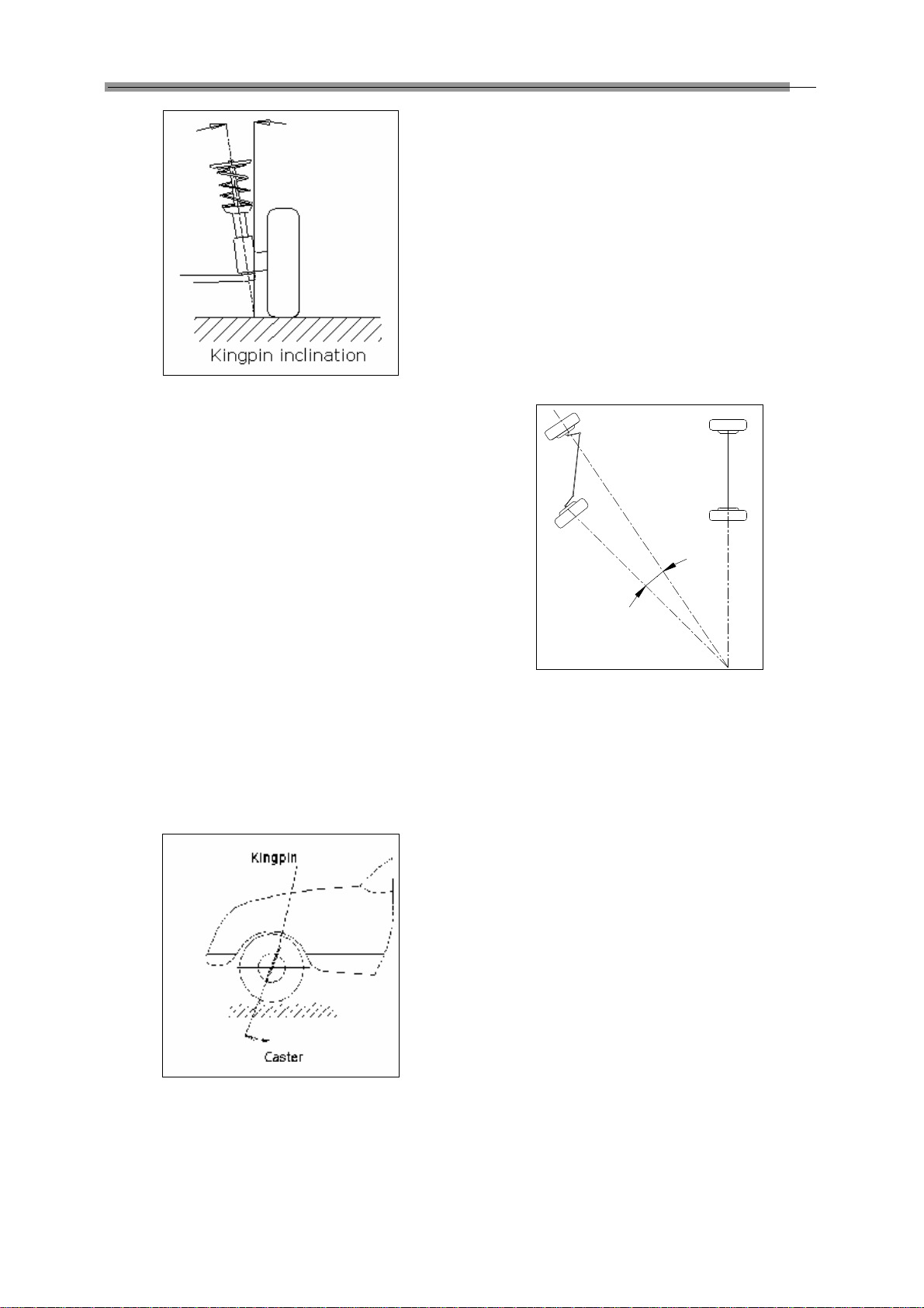
Kingpin Inclination..............................................1-1
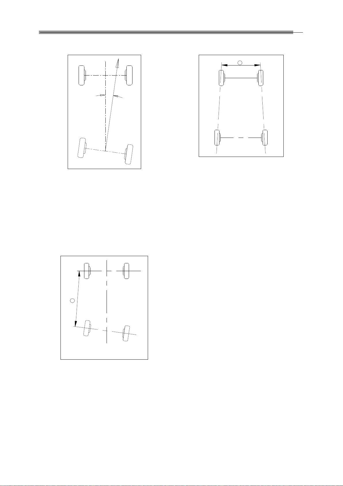
Caster................................................................1-2
Toe-out on Turns................................................1-2
Thrust angle.......................................................1-2
Wheelbase Difference........................................1-3
Tread Difference................................................1-3
Left (right) lateral offset angle............................1-3
Axle offset angle................................................1-3
Delay angle........................................................1-3
Included angle...................................................1-3
Functions and Features.........................................1-4
Specification...........................................................1-4
Requirements on Surroundings..............................1-4
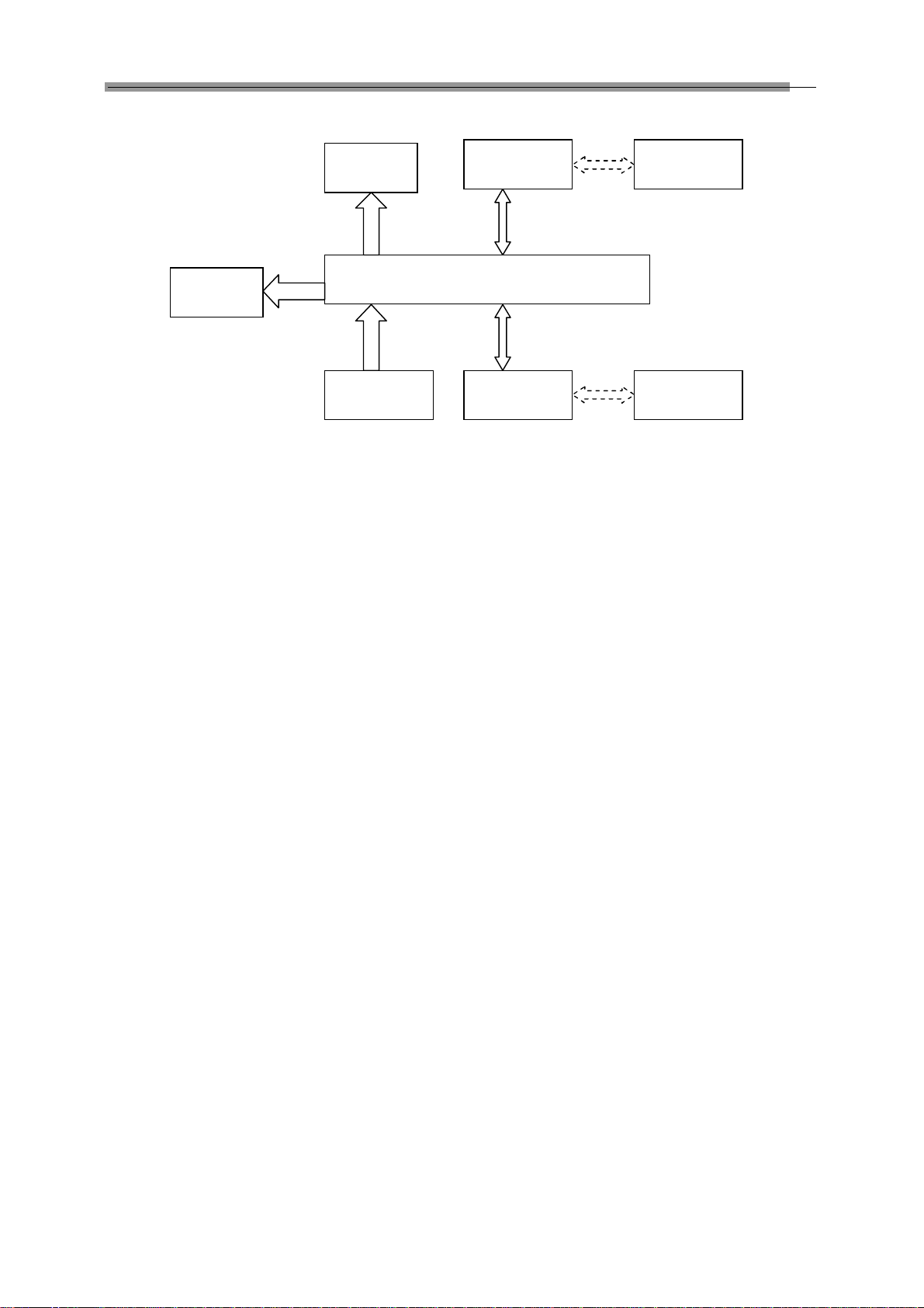
Working Principle...................................................1-4
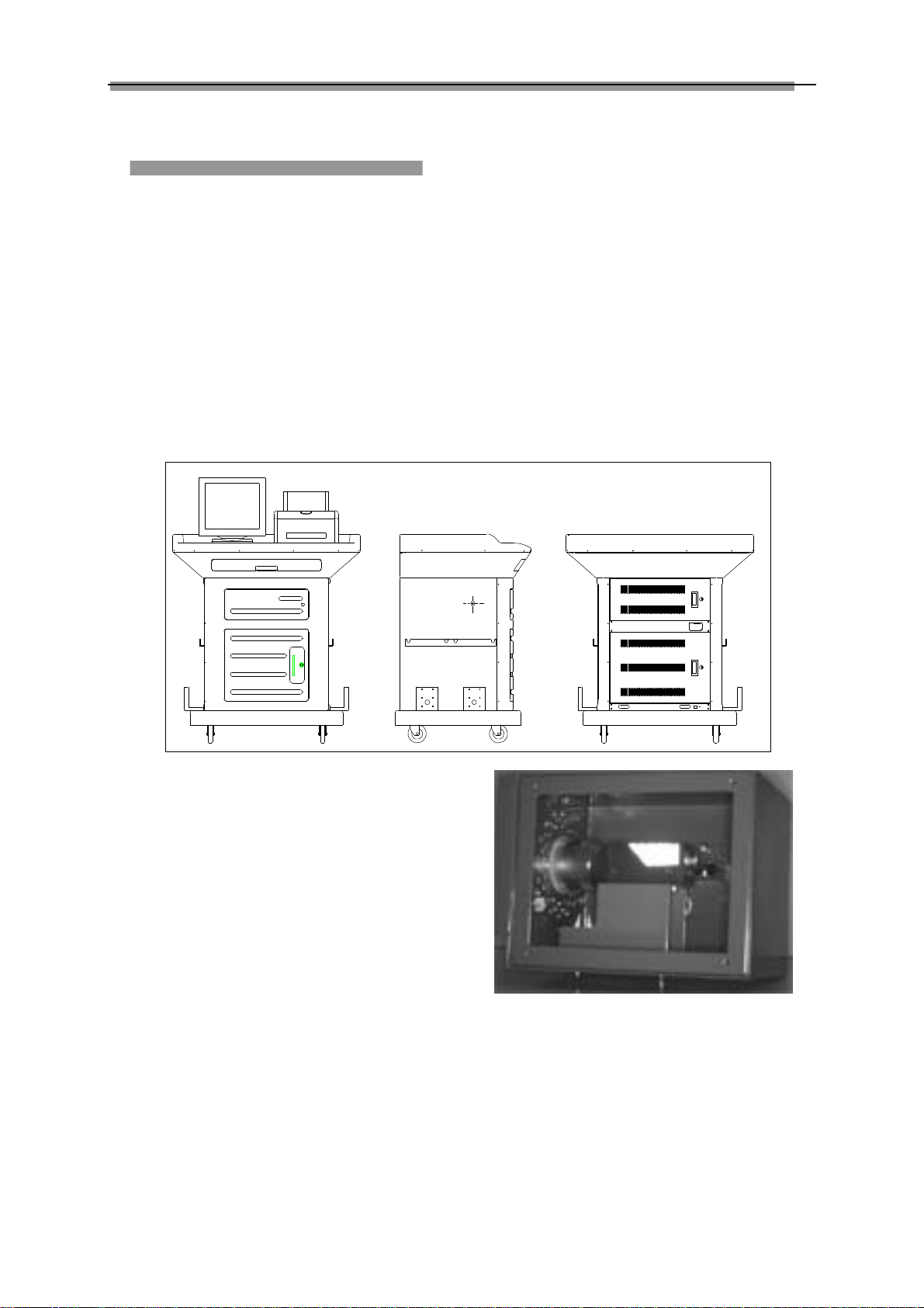
Structures..................................................................2-1
Overall Structures..................................................2-1
WheelAligner Main Unit.........................................2-1
Cameras and their posts........................................2-1
Wheel Clamps and Targets....................................2-2
Communication cables...........................................2-2
Turntables..............................................................2-2
Steering Wheel Holder...........................................2-2
Brake Pedal Depressor..........................................2-3
Wheel Clamp Tie....................................................2-3
Basic Operation Procedures...................................3-1
Get Vehicle Information..........................................3-1
WheelAlignment Checking....................................3-1
Adjustment.............................................................3-1
Test-drive................................................................3-1
Operation Instructions.............................................4-1
Preparation.............................................................4-1
Descriptions for pushbuttons..................................4-1
Vehicle Standards..................................................4-1
Data Query........................................................4-2
Data Edit............................................................4-3
User Management.............................................4-3
Client Management................................................4-3
AlignmentTest........................................................4-3
Register the Information of Vehicle to be Tested4-3
Test Setting........................................................4-4
StartTest............................................................4-7
System Calibration.............................................4-7
Target Monitoring...............................................4-7
CheckTest Result..............................................4-7
Language Setting...............................................4-7
Help........................................................................4-8
Exit.........................................................................4-8
Frequently Asked Questions (FAQ)........................5-1
Industrial Computer Cannot Start Up, WithoutAny
Prompts..................................................................5-1
Computer Cannot Enter Windows2000..................5-1
Mouse and Keyboard does not Respond...............5-1
Printer does not Respond......................................5-1
KWA-300 3D Program Does Not Run....................5-1
Why the blocking tip box does not appear when you
turn the steering wheel and block the rear target?.5-1
When you turn the steering wheel, the tip box
appears in case of the light path has been blocked,
how to handle it?....................................................5-1
Why does it have obvious difference between left
and right minimum turning radius after alignment?5-1
Maintenance..............................................................6-1
Computer...............................................................6-1
Wheel Clamp and Target........................................6-1
Printer.....................................................................6-1
Posts and signal cables.........................................6-1
Turntables..............................................................6-1

LAUNCH KWA-3003DWheelAlignerIntroduction
1-1
Introduction
Thank youfor using KWA-3003D wheel aligner
manufactured by LAUNCH TECH CO., LTD.
Definition
KWA-300 3D Wheel Aligner is aprecision
measurement instrument designed to measurethe
wheel alignment parameters and compare them
with the specifications provided by vehicle
manufacturer.It also gives instructions to the user
for performing corresponding adjustments so as to
get the beststeeringperformanceandreducetire
wear.
WhenIsWheelAlignment
Required
lThe driver mustfirmlyhold thesteering wheel
to maintain a straight-ahead driving.
lAbnormal wear of tires occurred, such as single
side wear,concave-convexity wear and
featheriness wear.
lToo heavy ortoolight steering, orshakingat
high-speed driving.
lWhen the tire(s), steering joint or shock
absorber are replaced.
lWhen the vehicle is impacted.
lWhen the vehicle has driven for the first
3000km or 10000km.
MainVehicleAlignment
Parameter
The wheel alignment mainlyconsistsof camber,
caster,toe-in, kingpin inclination, toe-out on turns,
wheelbase difference, tread difference, etc. They
are designed mainly toimprovethe steering
performance and driving stability of the vehicle,and
reduce tire wear.
Toe-inand Toe-out
The toe settingisthe amountbywhich thefrontor
rear wheels point inwardsor outwards atthe frontof
the wheel in relation to each other (see Fig.1.1).
When the wheels point inwards they are saidto
toe-in. Toe-in figures aregiven apositive value.
Conversely when the wheels point outwards they
are said to be toe-out and the figures are shown as
a negative value.
Fig.1.1
The purpose of correct toe isto ensure that the
wheels run parallel when thevehicle is driving.An
incorrect toe setting may affect the stabilityand
controllability of the vehicle.
Camber
Camber is the leaning of the wheel inwardsor
outwards from the vertical.
If the road wheel leans outwards from the vertical, it
is said to have positive camber and when leaning
inwards from the vertical -negative camber,looking
from the front or rear of the vehicle. See Fig.1.2.
Fig.1.2
Camber is measured in degrees.
KingpinInclination
Kingpin Inclination (KPI) is the angle ofinclinationof
the king pin towards thecentre-line of the vehicle
from the vertical (see Fig.1.3).

LAUNCH KWA-3003DWheelAlignerIntroduction
1-2
Fig.1.3
Correct KingpinInclination can equalizethe loads
applied on bearings so that the life of bearings can
be prolonged and thecontrollabilityof steeringis
improved.
Without the inclination, thecontrollability ofthe
steering may beaffected; further more,the vehicle
weight and the ground counterforce may cause
significant stress inthe axleand finallydamagethe
axle.
Correct inclinationof king pinis also helpfulforthe
vehicle to restore itsstraight-aheadposition after
steering.
Kingpin Inclination is determined when the vehicle
suspension is designed. It is not service adjustable.
Caster
Caster is thetilting ofthe kingpin eitherforwardsor
backwards from vertical, as viewed from side of the
vehicle. See Fig.1.4
Fig.1.4
When the king pin is tilted backwards from the
vertical, caster is positive. When the king pin istilted
forwards, caster is negative.
Caster angle influences thedirectional stabilityof
the steering. Toincreasethe tendency ofthe
steering to self-centre, the steering will normally be
designed with positive caster.
Toe-outon Turns
Toe-out on turns isdefined asthe difference ofthe
steering angle between the two front wheels when
turning left or right by 20°as shown in Figure 1.5.
The inner wheel will turn more degrees than the
outer wheel when the vehicle is steered, the
difference is usually about 2°.This angle is
designed to reduce steering resistance.
Fig.1.5
Note: This angle can be tested when aturntable
is equipped for KWA-300 3D.
Thrustangle
The trust angle is defined according to the driven
mode of vehicle.
lRear wheel driven: the thrust angle equals half
of the toe-in difference between the tworear
wheels.As shown in Fig.1.6.
lFront wheeldriven: the thrustangleequals half
of the toe-in difference between the two front
wheels.
lFour-wheel driven: the thrust angle equals half
of the toe-in difference between the two front
wheels plus half of the toe-in difference
between the two rear wheels.
The trust angle isdefinedas positivewhenthe trust
line is towards left, and negative when the line is
towards right.
If the thrust angle is not zero, the vehicle will have
the side-moving trend. In this case, adjust the front

LAUNCH KWA-3003DWheelAlignerIntroduction
1-3
toe-in of the drive wheels first, and then adjust the
toe-in of driven wheels.
Fig.1.6
Wheelbase Difference
Wheelbase difference is defined as the angle
between the jointline ofthe centreof two rear
wheels and thatof the front wheels.It is positive
when distance between the centre of the right
wheels is large than that of left wheels; and
negative otherwise. If the tread is available from the
vehicle specifications, then the wheelbase
difference can be also expressed byangle. See Fig.
1.7
+
Fig. 1.7
TreadDifference
Tread difference is defined as the angle between
the joint line of the ground-contact point of left
wheels and that of the rightwheels. It is positive
when distance between the centre of the rear
wheels is large than that of front wheels; and
negative otherwise. If the wheelbases are available
from the vehicle specifications, thenthe tread
difference can be also expressed byangle. See Fig.
1.8.
+
Fig. 1.8
Left(right)lateral offsetangle
The relative offset in lateral direction between front
axle and rear axle of vehicle is axle offset. When
rear wheel axle isoffset to right fromthe front wheel,
the axle offsetis positive, otherwise isnegative. The
angle between the bisector of the tread difference
angle and the thrust line is axle offset angle.
Axleoffsetangle
The relative offset in lateral direction between front
and rear axle of vehicle is axleoffset. When LR (RR)
wheel is offsetoutside fromLF (RF) wheel, theleft
(right) lateral offset is positive, otherwise is negative.
The angle betweenthe connectingline fromthe
front wheel center point to the rear wheel center
point (same side) and the thrust line is left (right)
lateral offset.
Delay angle
The angle between the connecting line from the LF
(LR) wheel center pointto theRF(RR) wheel center
point and the perpendicular ofthe longitudinal
geometry center line is called front (rear) delay
angle. Whenthe rightwheelon thefront (rear) axle
is behind the left wheel, the front (rear) delay (angle)
is positive, otherwise is negative.
Includedangle
The sum of the KPI (Kingpin inclination) and the
wheel camber is called included angle.

LAUNCH KWA-3003DWheelAlignerIntroduction
1-4
FunctionsandFeatures
lComplete test: The KWA-300 3D Wheel
Aligner can be usedto measurethe most
wheel alignmentparameters,such asfront
wheel toe-in, front wheel camber,caster,
Kingpin inclination, maximal steering angle,
thrust angle, toe-out on turns, rear wheel
toe-in, rear wheel camber,thrust angle,
wheelbase difference, tread difference, etc.
lBrand new 3D computer vision measurement:
automatically test the aligning angles with high
performance camera.
lPositive targets: thereare anyelectronic
elements inside the targets, and no cables
between the targets and the main unit, so the
targets are easy to be fastened onthe wheel
clamps.
lProvides many kinds ofauto testprocesses
and diagram operating interfaces, verysimple
and clear to operate;the whole test process
can be performed automatically,and there are
some humanitytips onthe corresponding
interfaces.
lComplete databank: wheel alignmentdata of
over 20,000 vehicle models is stored in the
system. User can also add new data to the
databank.
lAutomatically recordthe historydata, easy for
customer measurement.
lStandard printer to print test result.
lProvide real-time help with help system.
Specification
Item Resolution Test Range
Total toe-in ±0.03º0~±20º
Camber ±0.03º0~±20º
Caster ±0.06º0~±25º
Kingpin Inclination ±0.06º0~±25º
Maximal steering angle ±0.06º0~±30º
Maximal rim size 20 inches
Maximal wheelbase it can measure 4000mm
Notes:
1. The right of changing the design will be reserved by manufacturer;
2. The above accuracy can be confirmed only when the user follows the specified operation procedures.
RequirementsonSurroundings
Item Specification
Ambient temperature
0~+50℃
Relative humidity ≤85%
Light requirement No direct strong lights irradiate
the target and reflect to the
camera
The height difference
between the left rail <1mm (left to right); <2mm
(front to back)
and right rail of lift
Working Principle
The working frameworkof KWA-300 3D Wheel
Aligner is as shown in Fig.1.9. The whole system is
composed of data collecting system and data
processing system.

LAUNCH KWA-3003DWheelAlignerIntroduction
1-5
Fig.1.9
The data collecting system consists of 4cameras
with high resolutionand 4targets. The left and right
cameras capture the imageson theleft and right
targets, and transmit them to the data processing
system via the image collector.The targetsare
attached on the wheel rimsvia wheel clamps.So
the geometrical relationships among 4wheel rims
are calculated accordingto the images capturedby
cameras from thetargets andfurther toconfirmthe
aligning parameters of the wheels.
The data processing system is the main unit of
KWA-300 3D.It consistsof an industrial computer,
power supplysystem and interfaces. Itsfunctionis
to execute the operation commands, process the
data and display theinformation together withthe
original dataof vehiclemanufacturer.Italso gives
instructions for making adjustment to the vehicle
and print out corresponding report.
The wheel aligner comparesthe measured results
with the original data of vehicle manufacturer and
gives instructions to the user for adjustment, so its
databank should containenough information.
KWA-300 3DWheelAlignercontains wheel
alignment databank of over 20,000 vehicle types all
over the world. User can also add newvehicle
wheel alignmentdata inthedatabank when
necessary.
Industrial computer, image collector
keyboard、mouse
Printer
Monitor
Left camera
Right camera
Right
target
Lefttarget

LAUNCH KWA-3003DWheelAlignerStructures
2-1
Structures
Overall Structures
KWA-300 3D Wheel Aligner mainly consists of the
wheel aligner main unit, cameras and their posts,
wheel clamps, targets, communication cables,
mechanical turntables, steering wheel holder and
brake pedal depressor, etc.
WheelAlignerMainUnit
The main unit is an operation control platform. It
consists of cabinet, computergroup,interface circuit
system and power supplyassembly,etc.,as shown
in Fig.2.1.
The computer group includes industrial computer,
monitor,keyboard, mouse,printer and image
collector, etc. The monitor, mouse and printer are on
the top of the cabinet. The industrial computer is
inside the upper compartment ofthe cabinet,the
image collector is inside the industrial computer and
the keyboard is installed on the keyboard drawer.
The power supply assembly includes power lead,
power socket, tubefuse andthe powersupply main
switch. The power supply master switch pushbutton
is installed attheupper partof the leftsideboardof
cabinet, the tube fuse(AC2205A) is installedatthe
power supplysocket, and thepowersupply socket
is at the lower compartment of the cabinet.
Fig.2.1
Camerasandtheirposts
KWA-300 3D wheel aligner includes 4CCD
cameras, whichrespectivelycapturethe images
from the 4targets attached on the vehicle wheels.
The cameras are mounted inside the steel housings
as shown in Fig. 2.2. The accurate calibration for
camera has been performed during first installation,
so it isnot necessary foruser tocalibrateit when
using the instrument.
Fig.2.2
The two posts KWA-300 3D wheel aligner are used
for containing and fastening theCCD cameras and
their signal cables. The two posts are respectively
mounted on the ground with anchor bolts, and the
position relationship between the posts and the
cabinet is as shown in Fig. 2.3.
(Note: No matter during or after using, ensure to

LAUNCH KWA-3003DWheelAlignerStructures
2-2
prevent thepostsfrom swaying, otherwise the
position of camerawill be changed, influencing
the test result ).
Fig.2.3
Wheel ClampsandTargets
KWA-300 3D wheel aligner totally has 4
target-clamp assemblies, whichare thekey
components forwholetest system, andarethe
objects monitored by cameras. There are some
bull-eye signs for installing the wheel on the targets
as shown in Fig.2.4.
Fig.2.4
Whether the wheelclampsare fastenedcorrectlyor
not has the greatrelations withthe testresult. Turn
the adjusting knob to adjust the spanbetween
wheel claws until itis proper,and thenattachthe
clamp to the wheel rim. Adjust the knobto makethe
wheel clamp fixed on wheel rim tightly.Use the
wheel clamptie tobindthe wheelclampandthe
wheel rim together.
The installation of wheelclamp iscrucialto thetest
result. The claws should be in even contact with the
wheel rim without touching the lead weight.
Avoid hitting during operation. Otherwise, distortion
may be causedand thetest result maybe
influenced.
Communicationcables
There are 4signal cables and 2power supply
cables for infraredlight between the main unitand
the cameras of KWA-300 3D wheel aligner,which
should be fixedon theground atfirst installation,
and should be protected with the bushing. Ensure to
prevent the liquid from entering the inside of the
cable bushing or to avoid putting the heavy on it, in
order to prevent the bushing from being damaged.
Turntables
KWA-300 3D has two mechanical turntables
(standard configuration, see Fig.2.5).
Fig.2.5 mechanical turntables
The turntables are placedat the front wheel
positions of the vehicle on the lift.
Use the lock pin tolock the turntable before driving
the vehicle on.Pullout thelock pin afterthe vehicle
is stopped andthefront wheels areat thecentersof
the turntables.
While testing, try your best to keep the vehicle front
wheels at the centers of the turntables.
SteeringWheelHolder
KWA-300 3Dhas asteering wheel holderas shown
in Fig.2.6. Use the steeringwheel holderto lockthe
steering wheel according to the tips on the screen.
Fig.2.6 Steering wheel holder

LAUNCH KWA-3003DWheelAlignerStructures
2-3
Brake Pedal Depressor
KWA-300 3D hasabrake pedal depressoras
shown in Fig.2.7. It is used to hold the brake pedal
down.
Fig.2.7 Brake pedal depressor
Wheel ClampTie
The wheel clamp tie is shown in Fig.2.8. It is used to
bind the wheel clamp to the wheel rim. The hooks of
the tie catch on the wheel rim to prevent the wheel
clamp from accidentally falling, which may damage
the target and wheel clamp.
Fig.2.8 wheel clamp tie

LAUNCH KWA-3003DWireless WheelAlignerBasicOperationProcedures
3-1
BasicOperation
Procedures
Get VehicleInformation
Ask the owner for vehicle drivability problems,
symptoms, and wheel alignmenthistory,andfind
out vehicle information suchas make,modeland
year, etc.
Check each chassis part carefully,including rubber
boot, bearing, rock arm, tripod end, shock absorber,
tie rod end andsteering mechanism, forany
looseness or wear.Then check to see if thetire
pressure, tire treads of the left and right wheels are
alike.
WheelAlignmentChecking
Perform the wheel alignment checkingafterthe
initial condition is known.
Adjustment
If the measured values are not in accordance with
the specificationsgivenin thedatabank,the wheel
alignment adjustment should be performed.
Test-drive
After finishing thewheel alignment, testthe vehicle
to see if the abnormal conditions are eliminated.
Re-perform the wheel alignment if necessary.

LAUNCH KWA-3003DWireless WheelAlignerOperationInstructions
4-1
Operation Instructions
Preparation
I. Ask the owner for vehicle drivability problems and
symptoms, wheelalignmenthistory,andfind out
vehicle information such as make, model and
year, etc.
II. Drive the vehicle onto the lift or overthe pit,
ensure that the front wheels are centered with
the turntables; Apply hand brake to ensure
human safety.Topreventthe turntable from
turning, lockthe turntables withthelock pins
before drivingthe vehicle; releasethelock pins
after the vehicle is placed well.
III. Check each chassis part carefully,include dust
cover,bearing, rockarm, tripodend, shock
absorber,tie rod end and steering mechanism,
for any looseness orwear.Then check to see if
the tire pressure and treads of the left and right
wheels are alike.
IV. Install the wheel clamp-target assembly on the
wheel and turn the knob to lock the wheel clamp.
The claws of the wheel clamp should be fixed on
the external orinternaledge ofthe rim according
to the practical condition. Ensure equal depth for
each claw and avoid attaching it on the distorted
area. Use the safety belt to bind the wheel clamp
to the wheel rim to avoidfalling accidentally.
Please see Fig.4.1.
Fig.4.1
V. Insert the power plug of thewheel aligner into the
standard 3-pole power receptacle.
VI. Turn on the powersupply switch,start the
computer and enter the WINDOWS operating
system. Click the icon of KWA-300 3D Wheel
Aligner program to run the program.The screen
will displaythe mainfunctionmenu. There are6
functions available in themain menu, they are:
[Vehicle Standard],[User Management],
[Alignment Test], [Help System], [Language
Setting] and [Exit]. See Fig.4.2.
Fig.4.2
Descriptionsforpushbuttons
The meaningof themain functional pushbuttons in
this system is as follows:
for NEW;for EDIT;
for SAVE; for PRINT;
for DELETE for OK;
for STOP; for HELP,
for EXIT;for PREVIOUSE;
and for NEXT.
VehicleStandards
In the main function menu, please click icon of
[Vehicle Standard], thescreen willdisplay the
interface as shown in Fig.4.3.

LAUNCH KWA-3003DWireless WheelAlignerOperationInstructions
4-2
Fig.4.3
There are three functional options on this interface:
Data Query: to query alignment data of corresponding
vehicle models;
Data Edit: to edit and add the alignment data of new
vehicle models;
User Management:to provideawindow foruser to
input own information whichcan beprinted out when
printing the report forms.
DataQuery
Click the icon of [Data Query], the screen will display
the map of the world as shown in Fig.4.4.
Fig.4.4
Please click on the desired area on themap to the
corresponding database of the vehicle models in this
area, and the screen will display the automobile
manufacturers of the area you have selected, as
shown in Fig.4.5.
Fig.4.5
Double click on the manufacturer selected to enter
the database of this manufacturer,the screen will
display the manufacture year asshown in Fig.4.6.
Fig.4.6
Double click on theyear youhave selectedto enter
the specific vehicle modeldatabase of thisyear,the
screen will display the specific vehicle (and its model)
manufactured by the corresponding manufacturer at
this year as shown in Fig.4.7.
Fig.4.7
Double click onspecific vehiclemodel, thealignment
standard data will be shown on the right column. Click
[OK] pushbutton to finish selecting the standard data
of the vehicle model. If aselection error has been
made, please click [Previous] pushbutton to make
selection again.

LAUNCH KWA-3003DWireless WheelAlignerOperationInstructions
4-3
DataEdit
Click the icon of [Data Edit], the screen will display
the interface as shown in Fig. 4.8.
Fig. 4.8
Add thealignmentdataofnewvehicle
model
Please select area, manufacturer in turn and then
click the icon of [NEW], adding the vehicle model,
start year,end year,and then double click “…” edition
column; after the edition column becomes white, you
can add new data, and then pressthe iconof [SAVE ]
at last to finish adding data.
Modifythealignmentdataofoldvehicle
model
First, please selectthe corresponding area,
manufacturer and model of old vehicle, and then click
[MODIFY] pushbutton, and double click edition
column, you can modify the olddata, andthen press
the icon of [SAVE] at last to finish adding data.
UserManagement
Click the icon of[USER MANAGEMENT],the screen
will display the interface as shown in Fig.4.9.
Fig.4.9
Click [MODIFY] pushbutton, the adding column at the
lower part of the screen is highlighted, then you can
perform the edition modification; aftermodification,
please click [OK] pushbutton to savethe item
modified.
ClientManagement
Client informationis automatically savedin the client
information database after each test. In the main
function menu, pleaseclick the icon of [CLIENT
MANAGEMENT], the screen will display the interface
as shown in Fig.4.10.
Fig.4.10
After finding the desired client information, please
click [PRINT] pushbutton to print the client information,
and you can check the next client record by clicking
[NEXT] pushbutton.
AlignmentTest
In main function menu, please select the icon of
[ALIGNMENTTEST], the screen will display the
interface as shown in Fig4.11.
Fig4.11
There are several functions availablein above
interface: Register the Informationof Vehicleto be
Tested; Test Settings; Start Test; System Calibration;
Target Monitoring and ViewTest Result.
RegistertheInformation ofVehicletobe
Tested
Click the icon of [REGISTER THE INFORMATION OF
VEHICLE TOBE TESTED], the screen will display

LAUNCH KWA-3003DWireless WheelAlignerOperationInstructions
4-4
the interface as shown in Fig.4.12.
Fig.4.12
After searchingor addingtheinformationof the
vehicle to be tested, please click [OK] pushbutton to
save the information and return to the previous
interface.
TestSetting
Click the icon of [Test Setting], the screenwill display
the interface as shown in Fig.4.13.
Fig.4.13
In above interface, youcan selectAuto Test Itemsor
Manual Type Items, and can select Lifting Status Test
item. “√”indicates Starting This TestItem; “×”
indicates Not Starting This Test Item. First, please
select Auto Test Items orManual Type Items, and
then select the testcontent according to thedifferent
test requirements; please click the circular pushbutton
in front of thetest item toselect therequired test
content.
After selecting the testitem, please click[OK]
pushbutton to perform the test.
TestToe-in,Camber,KPI&Casterand
PrintTestResult
Note: 1) When testingtoe-inand chamber,please
move the wooden wedges away,fix the steering
wheel to pull and push vehicle, keep the force
equably during pulling and pushing; when testing
the kingpin, please movethe steering wheel
holder away in order to turn the steering wheel;
press downthe brake pedalwiththe brake pedal
depressor,andthen turn the steering wheel
equably.2)The system canautomatically identify
whether the installation of targets has satisfied
the conditions or not, andautomatically test
whether the targets have been blocked or not,
whether there is the strong infrared sources
which will influencethe testinside thevision field
of the cameras. Once the target has been blocked
during testing, the system will automatically pop
up atip boxfor blocking; after move blocking
materials away,the tip box will disappear,andthe
system will run normally again.
Select Test Toe-in, Camber,KPI &Caster andPrint
Test Result underthe Auto Test Itemscolumn, and
then click “√”(OK) pushbutton, thescreen will
display the interface as shown in Fig.4.14.
Fig.4.14
First, please click the icon of [Starting Test] to test the
Toe-in and Camber,the screen willdisplay the
interface as shown in Fig.4.15.
Fig.4.15
There is agreen arrow head on each wheel,which
instructs the operatorto pushthe vehicleslowly as
per the arrowdirection, after 20cm(approximately)

LAUNCH KWA-3003DWireless WheelAlignerOperationInstructions
4-5
passed, the screen will display the interface as shown
in Fig.4.16.
Fig.4.16
There is ared arrow head on each wheel, which
instructs the operator topullthe vehicleslowlyas per
the arrow direction,after 20cm(approximately)
passed(return to the original position), the screen will
display the interface as shown in Fig.4.17.
Fig.4.17
Several seconds later,the screen will display the
kingpin test interface as shown in Fig.4.18.
Fig.4.18
Please center thesteering wheel accordingto thetips
on the aboveinterface,andthen click theicon of
START TEST,thescreen will display theinterface as
shown in Fig.4.19.
Fig.4.19
Turn the steeringwheel right slowly according to the
tips on the aboveinterface, when the turning angle is
more than 20º,please turn the steering wheel left
slowly,the screen will display the interface as shown
in Fig.4.20.
Fig.4.20
Continue to turnthe steeringwheelleft accordingto
the tips on the interface, when the turning angle is
less than -20º,please turn the steering wheel right
slowly; when the littleball stay in 0ºposition, its color
become green from red, indicating that the steering
wheel has beencentered, andthen please lock the
steering wheel, the screen will display the interface as
shown in Fig.4.21.
Fig.4.21

LAUNCH KWA-3003DWireless WheelAlignerOperationInstructions
4-6
Click icon of [OK] to printthe reportform, andthen
click the icon of [Exit] to return to the main interface of
ALIGNMENTTEST.
Adjustthefrontwheels
Click the status symbol in front of the Auto Test Items
let it be “X”,then select Front Adjust under the
Manual Type Items, click [OK] pushbutton to enter the
FrontAdjust interface as shownin Fig.4.22.
Fig.4.22
Click the icon of [Start Test], the screen willdisplay
the value of fronttoe-in and front camberas shown in
Fig.4.23.
Fig.4.23
When the pointer foracertain parameter isout ofthe
green area, please adjust the corresponding wheel to
make the pointerbe inside thegreen area. Click the
icon of [Print] to enter into the interface of Print
Report, then click the icon of [OK] to print;Click the
icon of [Exit] toreturn tothe maininterface of
AlignmentTest.
The test procedures for the other test items are same
as the above test procedures, please perform them
according to the tips on the screen.
Generally speaking,only thestatic testneeds tobe
performed, the alignment parameter valuescan be
measured in case of the vehicle is stable. But inorder
to reduce the error caused bythe distortion of the
wheel rim and tire, it is suggested toselect wheel
static compensation test function to ensure
measuring accuracy.
In the interface of [Test Option] as shown in Fig.4.13,
please click the Static Compensation pushbutton,
then click [OK] pushbutton to enter into the[Static
Compensation] interface as shown in Fig.4.24.
Fig.4.24
In the aboveinterface, please clickthe iconof
to select thewheelto beadjusted, and thenpress the
icon of to perform the wheel compensation
test as shown in Fig.4.25.
Fig.4.25
After finishing compensationtest for four wheels,
please press the icon of to calculate toe-in
and camber compensated as shown in Fig.4.26.

LAUNCH KWA-3003DWireless WheelAlignerOperationInstructions
4-7
Fig.4.26
StartTest
After all settings have been finished, you can perform
the wheel alignmenttest. Pleaseclick Start Test icon
in the Alignment Test interface, the instrument will
perform the test according to the test items and the
test methods set above.
SystemCalibration
Only the specializedperson fromLaunch can perform
this kind of operation, itis not necessary foruser to
do it. Pleasereferto KWA-300 3D WheelAligner
Installation and Parts Manual for details.
TargetMonitoring
Target monitoringneedsto performed before test,
click the icon of [Target Monitor], the screen will
display the interface as shown in Fig.4.27.
Fig.4.27
The upper column ofthe aboveinterfaceis the
functional pushbutton display area, the middle part of
the interface is the target image display area, and the
bottom column of the interface is the target centers
position displayarea. The targetmonitoringinterface
can display the fourtarget images at thesame time
(default interface), also it can display any one of the
four target images,you can select the image to be
displayed by clickingthe corresponding functional
pushbutton on theuppercolumn ofthe interface. The
functional pushbuttons, such as Restore Target
Image, Zoom in Target Image, Zoom out Target
Image and Move Target Image, etc. are available only
in case of the single target image is displayed.
If the greyscaleof thetargetcan not bedistinguished,
please adjust the target and its corresponding camera
in order to let the target be onthe appropriate
position.
Check TestResult
Click the icon of [Check Test Result] in the main
interface, the screen willdisplaythe interface as
shown in Fig.4.28.
Fig.4.28
This function is used to check the data saved in the
previous test, e.g. after finishingthe test forthe single
wheel, the screen will not display the testresult, you
can check the test result by entering this function
interface. Click pushbutton to change over the
adjustment result interfaces; click [Exit]pushbutton to
return to the previous interface.
LanguageSetting
Click [Language Setting] icon on the main interface,
the screen will display language setting dialogue box
as shown in Fig.4.29:
Fig.4.29

LAUNCH KWA-3003DWireless WheelAlignerOperationInstructions
4-8
After selecting thedesired language:Simplified
Chinese or English, please click [OK]pushbutton to
confirm.
Help
User can press F1 key or click [HELP] button to enter
the help system on any interface. The help subject
depends on the content of the current screen. User
can also select [Content] or [Index] to enter the
interested help subject after entering the help system,
see Fig.4.30.
Fig.4.30
The help system includes the following information:
lOperation of wheel aligner software
lBasic knowledge on 4-wheel alignment
Exit
Click [Exit] button on the mainmenu, thecomputer
will exit the wheel alignment program and enter the
Windows operating system.
Table of contents