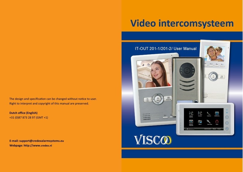
Visco IT-OUT250 User manual

The design and specicaon can be changed without noce to user.
Right to interpret and copyright of this manual are preserved.
Dutch office (English)
+31 (0)87 87 32897 (GMT +1)
E-mail: support@credexalarmsystems.eu
Webpage: http://www.credex.nl
IT-OUT250 / User Manual

Contents
1. Parts and Funcons..............................................................................................03
2. Terminal Descripons...........................................................................................03
3. Door Staon Mounng.........................................................................................04
4. System Wiring and Electric Lock Connecon........................................................06
5. DIP Switches Seng..............................................................................................12
6. ID Card Registraon..............................................................................................14
7. Unlock Operaons................................................................................................16
8. Precausons..........................................................................................................17
9. Specicaons........................................................................................................17
10. Cables Requirements............................................................................................18
! Please read this manual carefully before using the product, and keep it well.
www.viscoo.eu
www.viscoo.eu

www.viscoo.eu
10. Cables Requirements
The maximum distance of the wiring is limited in the DT system. Using dierent
cables may also aect the maximum distance which the system can reach.
IT-MPIN
www.viscoo.eu
1. Parts and funcons
2. Terminal Descripons

www.viscoo.eu
• JP/LK (Lock Control Jumper): To select the lock type: see secon 4
• Doorstaon Code DIP: Total 4 door staons can be supported, see secon 5
• RS485: Used to update the program for door staon
• MIC: Adjust the volume of Microphone
• SPK: Adjust the volume of Speaker
• Main Connect Port: To connect the bus line and the electronic locks.
• BUS: Connect to the bus line, no polarity.
• PL: External lock power input, connect to the power posive (power +).
• S1+, S2+: Lock power(+) output, to connect 2 locks.
• S-: Lock power(-) output, connect to the power(-) input of locks(only when using the
camera to power the locks, if using the external power supply for the locks, the S-
will not be connected).
IT-OUT250 Mounng
3. Door Staon Mounng
www.viscoo.eu
• You can acvate the electric door strike by pressing the request to exit buon con-
nected to the unit. Pressing request to exit buon 1 releases relay 1, and pressing
request to exit buon 2 releases relay 2.(The unlock funcon will work when the
request to exit buon is pushed, even while the proximity access is forbidden.
1. If show the authorized user card,the buzzer will sound of beep+,and the
LED indicator will light up.
2. If show the unauthorized user card, the buzzer will sound of beep, beep,
beep.
8. Precausons
•Please clean the unit with so coon cloth, don't use the organic impregnant or
chemical clean agent. If necessary, please use a lile pure water or dilute soap
water to clean the dust.
•The unit is weather resistant. However do not spray high pressure water on ac-
cess control keypad directly. Excessive moisture may cause problems with the
unit.
•You must use the right adaptor which is supplied by the manufacture or approved
by the manufacture..
•Pay aenon to the high voltage inside the products, please refer service only to
a trained and qualied professional.
9. Specicaons
•Power Supply: DC 24V (supplied by PS4-24V or PS5-24V);
•Power Consumpon: Standby 60mA; Working status 200mA;
•Camera: Pinhole Sharp Color CCD; 420 TV Lines;
•Lock Power supply: 12Vdc, 300mA (Internal Power);
•Number of relay circuits: 2
•Mounng: surface mounng(IT-OUT250) Flush mounng (IT-OUT250-F)
•Working temperature: -10ºC ~ +45ºC
•Wiring: 2 wires, non-polarity
•Dimension: 176(H)×90(W)×28(D)mm(DT596/ID)
220(H)×119(W)×52(D)mm(DT596F/ID)

www.viscoo.eu
By default,there are two master cards marked MASTER CARD ADD and MASTER
CARD DELETE ,but you should know that the master card can be authorized by users
at any me.That means any two user cards can be authorized to master cards,When
registered new master cards, the old master cards are invalid automacally.
Authorize master cards:
7.Unlock Operaons
Unlocking of ID Card
When the registered user card has been shown to ID card window, the LED indicator
(the rst lock:red; the second lock:blue) lights up, the buzzer sounds,and the electric
door strike is unlocked.
Note1:if the user card control one lock only,show the user card to release the rst
lock.red indicator lights up.
Note2:if the user card control two locks,show the user card to ID card window in
standby mode,the red&blue indicator blink for 1.5s alternately. During this -
me,press "CALL" buon to release the second
lock.Otherwise,release the rst lock if there
isn't any operaon within 1.5 seconds.
• If 10 mes unauthorized access cards are connuously aempted, the release
funcon is forbidden and the showing card operaon is disabled for 60 seconds.
• When DIP3 switch is set to 1,the relay 2 doesn't respond the second lock,that's to
say,showing user cards controlled two locks or pressing unlock 2nd on monitor
can not release the second lock.During this me,Aer connuously showing ac-
cess card 10 mes,the relay 2 will be closed for 60 seconds,the blue LED-relay 2
will be illuminated for 60 seconds,and the buzzer will connuously sound about 8
mes.If the system is connected alarm,the alarm funcon will be acvated.
www.viscoo.eu
IT-OUT250-F Mounng
Adjusng Camera Angle

Placing Name Label
www.viscoo.eu
Press the plasc cover on right/le side to move away the cover,insert a name paper,
then put the plasc cover back to the panel. RF
Basic Connecon
4. System Wiring and Electric Lock Connecon
IT-PS01 IT-PSU24
www.viscoo.eu

www.viscoo.eu
Bit-6 is used to match the video impendance, which have to be set to on if the monitor is in the
end of the bus, otherwise set to o.
Bit-1 to Bit-5 are used to User Code seng.The DT596(F)/ID responds to 0~15 .
•Up to 1000 user cards can be registered by the door staon.
•Easy management with LED status and sound hints.
•There are two master cards, one MASTER CARD ADD card and one MASTER
CARD DELETE card, When registered new master cards, the old master
cards are invalid automacally.
•Card reading distance is from 3 to 5 cm.
•The master cards are necessary when you add or delete user cards. Please
keep it well for future use.
Introducon:
6. ID Card Registraon
www.viscoo.eu
Electric Lock Connecon
Door Lock Controlled with Internal Power
Note:
1. Electronic lock of Power-on-to-unlock type should be used.
2. The door lock is limited to 12V, and holding current must be less than 250mA.
3. The door lock control is not med from Exit Buon(EB).
4. The Unlock Mode Parameter of Monitor must be set to 0 (by default). EB*
Door Lock Controlled with Dry Contact
Note:
1. The external power supply must be used according to the lock.
2. The inside relay contact is restricted to AC or DC 24V/1A.
3. The jumper must be taken o before connecng.
4. Setup the Unlock Mode of Monitor for dierent lock types.
• Power-on-to-unlock type: Unlock Mode=0 (by default)
• Power-o-to-unlock type: Unlock Mode=1

www.viscoo.eu
Note:
1.must connect IT-OUT250-F correctly before seng.
2.the parameter will be saved in IT-OUT250-F automacally, so you need only set on
one monitor.
3.the above diagram is t for icon menu series monitors only, to text menu series
monitors, please refer to the corresponding user manual.
www.viscoo.eu
DIP Switches Sengs of Door Staon
Total 4 bits on the DIP switches can be congured. The switches can be modied
either before or aer installaon.
5. DIP Switches Seng
There are 6 bit switches in total. The DIP switches are used to congure the user code
for each Monitor.
DIP Switches Sengs of Monitor

www.viscoo.eu
Extending Connecons with IT-CCTV unit
IT-MPIN
IT-CCTV
IT-CCTV IT-PS01 IT-PSU24
IT-MPIN
www.viscoo.eu
Mul Door Staons Connecon
IT-MPIN IT-PS01 IT-PSU24

www.viscoo.eu
Basic IN-OUT Wiring Mode
Mul Monitors Connecon
IT-PSU24
IT-PS01
www.viscoo.eu
With IT-MPIN Wiring Mode
IT-PS01 IT-PSU24
IT-MPIN
IT-MPIN
Table of contents
Other Visco Intercom System manuals