Vision UPS Systems Spirit G XL 1KVAS User manual

User manual
Spirit G XL
1-3 KVA –PF0.9
U
ninterruptible
P
ower
S
upply

SPIRIT G XL 1-3 KVA - PF0.9 -UPS www.visionups.com
2
All rights reserved.
The information in this manual is subject to change without notice.
Thank you for purchasing this series UPS. It is secure and reliable and requires only low maintenance.
Please read this manual carefully and entirely. It contains instructions about safety, installation and operation. These will help
you to reach maximum life time of your UPS. This manual explains the inner working principle and the corresponding
protective functions. Furthermore, it contains information regarding the use of the equipment.
Carefully follow the given instructions and warning messages in this manual or on the device itself. Only use the equipment
once you had fully read the safety and operation instructions.
Remark: Our products might differ slightly from the data in this manual due to continual improvements. If needed contact a
local representative to get further information.

SPIRIT G XL 1-3 KVA - PF0.9 -UPS www.visionups.com
3
TABLE OF CONTENTS
1. Introduction……………….…..…………………………….….…………………………………………..….……………………………. 5
2. Safety Warnings...….……...………………………........................................................................................... 6
3. Installation …………………………………………….…………………………............................................................... 7
3.1. Unpacking and Inspecting the Equipment..………………...…….................................................. 7
3.2. Checking the accessories..….……..….……….………………………..................................................... 7
3.3. Rack mount Installation..………………………………………………..………….......................................... 8
3.4. Rack mount Wiring Installation……...…….……………………………................................................. 9
3.5. Connecting the Battery Packs (EBPs)…………….……….………….................................................. 11
3.6. Rack mount converted to Tower Installation…………………………………….…............................... 12
3.7. UPS Initial Start-up……………….……………….…………………………………………………………………………. 14
4. Display Monitor, Operation and Control………………………..….…...…....................................................... 15
4.1. Control functions…………………………………................................................................................ 15
4.2. Display Functions…….……………………………………………………...................................................... 17
4.3. Parameters Inquiring………….………..…….…………………………….................................................. 18
4.4. Parameter Settings………………..………………………..................................................................... 19
4.5. Start up and Turn off the UPS..……………………........................................................................ 23
5. Communication….……………………….….…………………............................................................................... 25
5.1. Communication Options and Control Terminals…................................................................. 25
5.2. RS232 and USB Communication Ports……….……..……………………………………………………………… 26
5.3. Connectivity Cards..…………………………………………………………………………….………………………...... 26
5.4. Emergency Power Off (EPO)…………….…………………………………………………............................... 27
5.5. Load Segments.......……………………………………………………………………………….............................. 28
5.6. UPSilon2000 Power Management Software…………………………………………………………………….. 28
6. Maintenance.……………………………………………………..……....….................................................................. 29
6.1. Maintenance of UPS and Batteries.………………….................................................................... 29
6.2. Storing the UPS and Batteries…..……………............................................................................. 29
6.3. Replacing the Batteries…………………………………...................................................................... 29
6.4. Replacing the UPS (R/T) and Battery Packs (EBPs)……........................................................... 30
6.5. Testing New Batteries…..…………......…………………................................................................... 30
6.6. Recycling the Used Batteries and the UPS………………………………………………………………………… 31
7. Specifications…..…………………………………………………..……....…................................................................ 31
7.1. Model Specifications..……………….…………………….................................................................... 31
7.2. Rear Covers……………………………..………………........................................................................... 35
8. Troubleshooting………...………………………………………..……....…................................................................ 36
CONTENT LIST OF TABLES
Table 1 Indicator descriptions…………………………………………………………………………………………………….. 15
Table 2 Button functions..…………………………………………………............................................................ 15
Table 3 Operating status corresponding to indications………..…………………………………………………….. 16
Table 4 LCD Display ……………………………………………………………..…………………………………………………….. 17
Table 5 Parameters inquiring..……………………………..…………………………………………………………………….. 18
Table 6 Parameters settings………………………………..……………….…………………………………………………….. 19
Table 7 Operation modes…………………………………….………………..…….…………………………………………….. 22
Table 8 Battery number configuration…………….……………………..………………………………………………….. 24
Table 9 Pin assignment of RS232 communication port….……………………………………………………………. 26
Table 10 Communication options…………………………………….......…………………………………………………….. 31
Table 11 Extended battery model…………………………………………………………………….………………………….. 31
SPIRIT G XL 1-3 KVA - PF0.9 -UPS www.visionups.com
4
Table 12 UPS models……..…………………………………………………………………………………………………………….. 31
Table 13 Weights and dimensions………..………………………………………………………………………………………. 32
Table 14 Electrical input A. ………………………………………………………………………………………………………….. 32
Table 15 Electrical input B. ………………………………………………………………………………………………………….. 32
Table 16 Electrical input connections…….…………………………………………………………………………………….. 32
Table 17 Electrical output…………………………………………………………………………………………………………….. 32
Table 18 Electrical output connections…………………………………………………………………………………………. 33
Table 19 Environment and safety………………………………………………………………………………………………….. 33
Table 20 Internal charger…….……………………………………………………………………………………………………….. 34
Table 21 Battery runtimes at 100% load….……………………………………………………………………………………. 34
Table 22 Battery...……..…………………………………………………………………………………………………………………. 34
Table 23 Troubleshooting….…………………………………………………………………………………………………………. 36
Table 24 Warnings messages and fault codes….…………………............................................................. 37
-----------------------------------------------
Class B EMC Statements –FCC Part 15
This equipment has been tested and found to comply with the limits for a Class B digital device, pursuant to part 15 of the
FCC Rules. These limits are designed to provide reasonable protection against harmful interference in a residential installation.
This equipment generates, uses and can radiate radio frequency energy and, if not installed and used in accordance with the
instructions, may cause harmful interference to radio communications. However, there is no guarantee that interference to
radio or television reception, which can be determined by turning the equipment off and on, the user is encouraged to try to
correct the interference by one or more of the following measures:
Reorient or relocate the receiving antenna.
Increase the separation between the equipment and the receiver.
Connect the equipment into an outlet on a circuit different from that to which the receiver is connected.
Consult the dealer or an experienced radio/TV technician for help.
Special Symbols
The following are examples of symbols used on the UPS or accessories to alert you to important information:
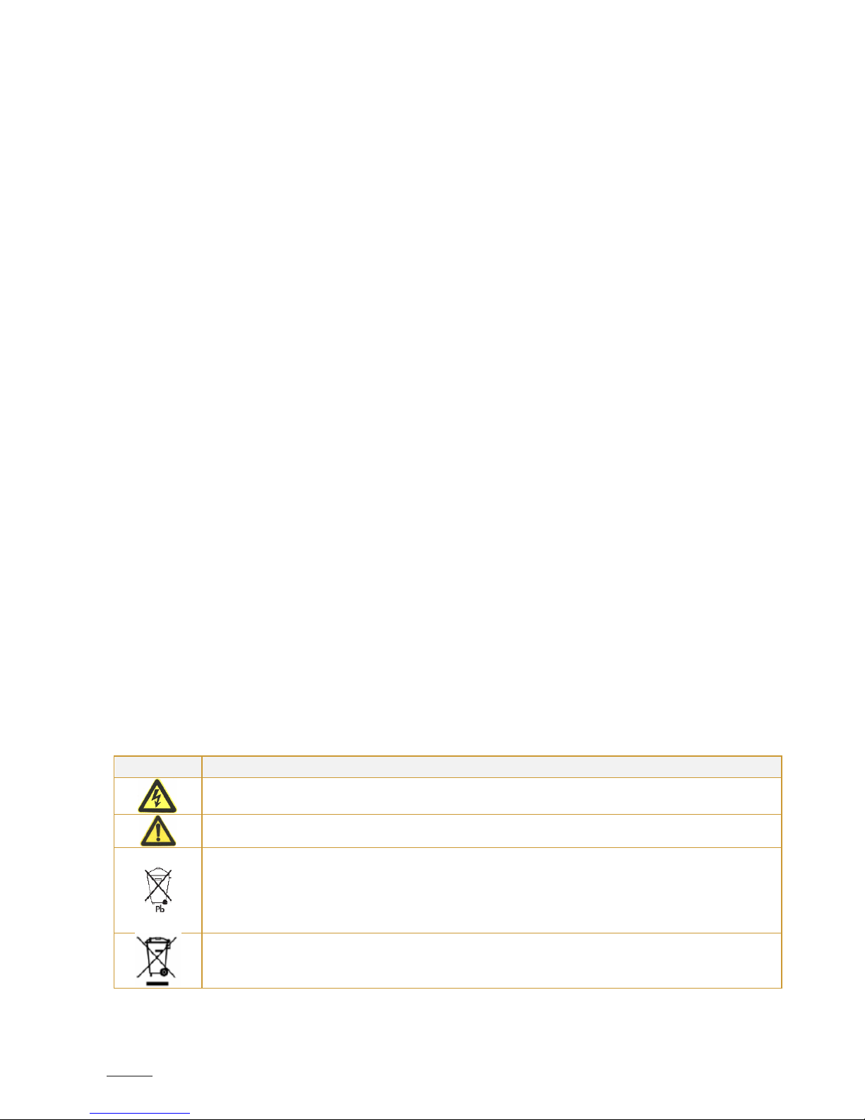
Symbol
Indication
Risk of electric shock – Observe the warning associated with the risk of electric shock symbol
Caution – need your attention
Indicates that you should not discard the UPS or the UPS batteries in the trash. This product contains
sealed, lead-acid batteries and must be disposed of properly. For more information, contact your
local recycling/reuse or hazardous waste center.
Indicates that you should not discard waste electrical or electronic equipment (WEEE) in the trash.
For proper disposal, contact your local recycling/reuse or hazardous waste center.
SPIRIT G XL 1-3 KVA - PF0.9 -UPS www.visionups.com
5
1. INTRODUCTION
This UPS protects your sensitive electronic equipment from most common power problems, including power failures, power
sags, power surges, brownouts, line noise, high voltage spikes, frequency variations, switching transients and harmonic
distortion.
Power outages might occur unexpectedly and power quality can be erratic. These power problems have potential to corrupt
critical data, destroy unsaved work sessions and damage hardware –causing hours of lost productivity and expensive repairs.
With the UPS, you can safely eliminate the effects of power disturbances and guard the integrity of your equipment. Providing
outstanding performance and reliability, the UPS’s unique benefits include:
True online double-conversion technology with high power density, utility frequency independence and generator
compatibility. Output power factor up to 0.9.
Three segment charging mode to increase battery service life, optimize recharge time.
Selectable High Efficiency mode of operation.
Cold start function to start-up the UPS without utility.
Standard communication options: one RS232 communication port, one USB communication port and relay output
contacts or SNMP card.
Power shedding function may turn off uncritical load in battery backup to make longer backup time for critical load.
Extended runtime with up to four Extended Battery Modules (EBPs) per UPS.
Emergency shutdown control through the Remote Emergency Power-off (EPO) port.
The content displayed on the interface is rich. The capacity of the loads and the battery can be seen directly and the
FLASH pictures and fan rotating icon can be displayed while charging. Enhance, it is easy to know its operation status.
When UPS fails, it can show the fault code; therefore, the UPS can be repaired as soon as possible by inquiring fault
code table.
NOTICE: In the manual, RT is short for Rack-Tower conversion.
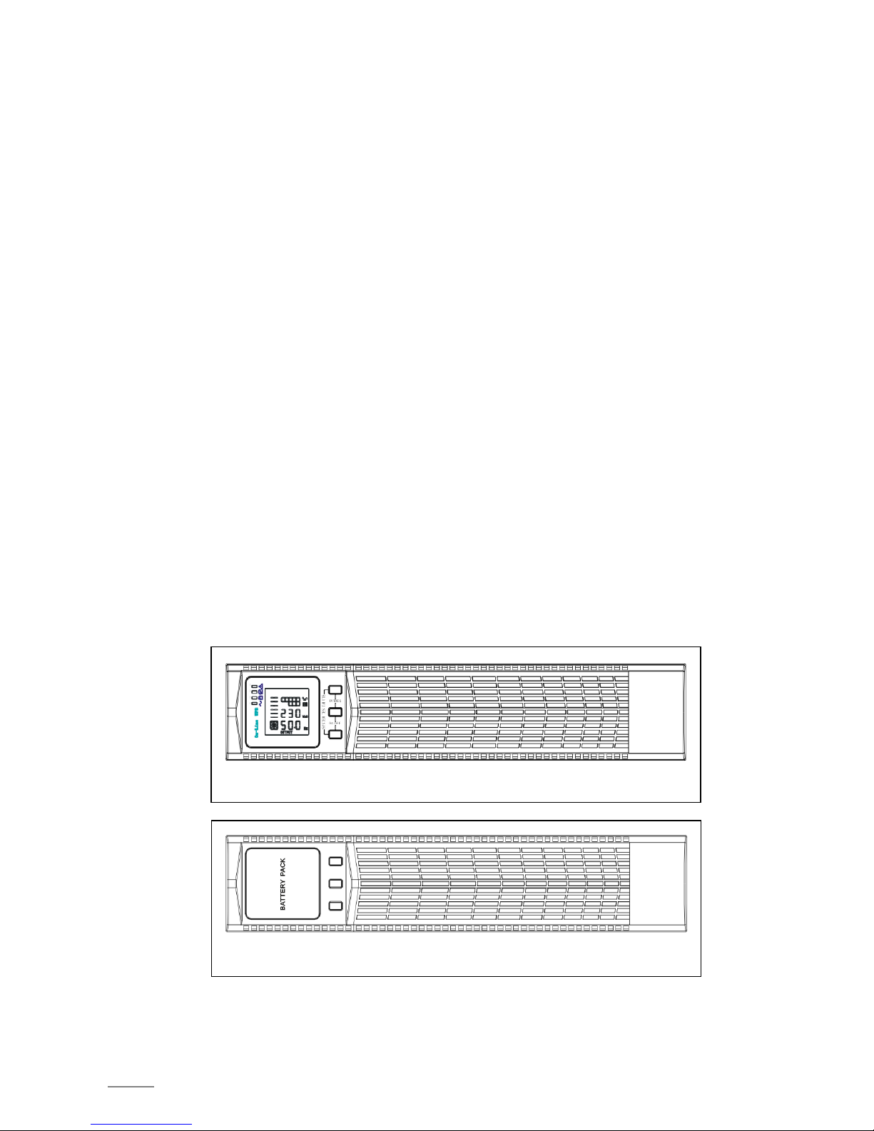
Rack/Tower convertible LCD design. No matter what angle required, only pressing the key slightly to reach your
perspective needs.
For RT model, it is equipped with hot swappable battery feature needed for 19“rack solution.
RT models in a space-optimizing 2U size fits any standard 19“rack.
Fig. 2 –The Rackmount EBP front view
Fig. 1 –The Rackmount UPS front view
SPIRIT G XL 1-3 KVA - PF0.9 -UPS www.visionups.com
6
2. SAFETY WARNINGS
This chapter contains important instructions that you should follow during installation and maintenance of the UPS and
batteries. Please read all instructions before operating the equipment and save this manual for future reference.
Following the safety instructions:
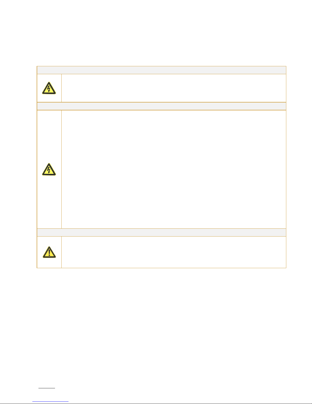
DANGER
The UPS contains lethal voltages. All repairs and service should be performed by authorized service
personnel only. Please follow the local safety regulations and corresponding laws during installation,
operation and maintenance; because otherwise it may result in injury and/or equipment damage. The
safety instructions in this manual serve in addition to the local valid safety regulations.
There are no user serviceable parts inside the UPS.
WARNING
The UPS contains its own energy source (batteries). The UPS output may carry live voltage even when
the UPS is not connected to an AC supply.
To reduce the risk of fire or electric shock, install the UPS in a temperature and humidity controlled,
indoor environment, free of water, corrosive gases, conductive contaminants or strong dust formation.
Ambient temperature must not exceed 40°C. But to preserve batteries lifetime, we advise you to an
operating temperature of 20°C to 25°C.
Do not place any liquids on the UPS cabinet in order to not trigger electrical discharges nor other
dangers.
To reduce the risk of fire, connect only to a circuit provided with branch circuit overcurrent protection
in accordance with the National Electrical Code (NEC), ANSI/NFPA 70.
Output overcurrent protection and disconnect switch must be provided by others.
To comply with international standards and wiring regulations, the sum of the leakage current of the
UPS and the total equipment connected to the output of the UPS must not have an earth leakage
current greater than 3.5 milliamperes.
If installing optional rack mount EBP(s), install the EBP(S) directly below the UPS so that all wiring
between the cabinets is installed behind the front covers and is inaccessible to users. The maximum
number of EBP(s) per UPS is four.
If the UPS requires any type of transportation, verify that the UPS is unplugged and turned off and then
disconnect the UPS internal battery connector.
CAUTION
Batteries can present a risk of electrical shock or burn from high short-circuit current. Observe proper
precautions. Servicing should be performed by qualified service personnel knowledgeable of batteries
and required precautions. Keep unauthorized personnel away from batteries.
Proper disposal of batteries is required. Refer to your local codes for disposal requirements.
Never dispose of batteries in a fire. Batteries may explode when exposed to flame.

SPIRIT G XL 1-3 KVA - PF0.9 -UPS www.visionups.com
7
3. INSTALLATION
This section explains:
-Equipment unpacking and inspection;
-Checking the accessory kit;
-Cabinet installation;
-Wiring installation;
-Initial start-up.
3.1. Unpacking and inspecting the Equipment
3.1.1. Unpack the UPS and check it for any transport damage. Do not put the unit into operation in case of damage
or of missing parts and keep all packing material for the forwarder and/or dealer. Inform the forwarder and
the dealer.
3.1.2. Check if the delivered equipment is indeed the one you wanted to buy. You can do that by checking the
model number on the unit rear side.
3.1.3. CAUTION:
Unpacking the UPS in a low-temperature environment may cause condensation to occur in and on the
cabinet. Do not install the cabinet until the inside and outside of the cabinet are absolutely dry (hazard
of electric shock).
The UPS is heavy (see page 32 «Weights and dimensions»). Be careful to unpack and move the
equipment.
3.1.4. Place the UPS in a clean and solid location. Avoid places with vibrations, dust, high humidity, flammable gas,
liquids and corrosion.
3.1.5. The ambient temperature must not exceed 40°C maximum. To preserve batteries lifetime, we advise an
operating temperature of 20°C to 25°C.
3.1.6. The UPS must be installed in a location with sufficient ventilation.
3.2. Checking the accessories
3.2.1. The accessory of inverter contains:
- UPS user’s manual;
- Software-Suite-CD;
- USB cable;
- Power cord (input and output);
- RS232 cable;
- In case of an ordered optional Extended Battery Module (EBP): manual of EBP.
Note: Discard the EBP user manual if you are installing the EBP with a new UPS at the same time. Use the
UPS user manual to install both –UPS and EBP.
3.2.2. The accessory of rail kit (options) –check if following rail kit items are included for each inverter:
a) Left rail assembly: left rail, rear rail, 3 x pan-head screws M5_8.
b) Right rail assembly: right rail, rear rail, 3 x pan-head screws M5_8.
c) Rail hardware kit: 8 x butterfly nuts M5, 2 x rear stop brackets, 8 x umbrella nuts M5.
d) Mounting bracket kit: 2 x mounting brackets, 8 x flat-head screws M4_8.
3.2.3. Tools required –to assemble the components, you need the following tools: cross-shaped screwdriver,
wrench or socket of 6mm.

SPIRIT G XL 1-3 KVA - PF0.9 -UPS www.visionups.com
8
3.3. Rack mount Installation
3.3.1. Rack Installation:
The rack mount cabinet is delivered with all accessories, which are required for installation on a standard
EIA or JIS seismic rack mount configuration with square and round mounting holes.
In 19”-racks, the rail assemblies can be adjusted in depth from front to rear around 50cm until approximately
80cm.
3.3.2. PRECAUTIONS during the Rack-Mount:
The cabinet is heavy. Removing it from its carton requires a minimum of two people.
If installing optional EBP(s), make sure to install the EBP(s) directly below the UPS in order that all wiring
between inverter and external batteries is installed behind the front cover and thus inaccessible to
users.
NOTE: mounting rails are required for each individual cabinet.
3.3.3. Installation of the rail kit:
①Assemble the left and right rails to the rear rails as shown in figure 3 below. Do not over tighten the
screws. Adjust each rail size for the depth of your rack.
②Select the proper size in the rack for positioning the UPS (see fig. 4). The rail occupies four positions
on the front and rear of the rack.
③Tighten four M5 umbrella nuts in the side of rail assembly (see fig. 3).
④Fix one rail assembly to the front of the rack with one M5x12 pan-head screw and one M5 cage nut.
Use two M5 cage nuts and two M5x12 pan-head screws to fix the rail assembly to the rear of the
rack.
Fig. 3 –Assembly of the rails
Fig. 4 –Fixing the rails

SPIRIT G XL 1-3 KVA - PF0.9 -UPS www.visionups.com
9
⑤Repeat the steps ③ and ④ to assemble the other rails.
⑥Tighten the four butterfly nuts in the middle of each rail assembly.
⑦If installing optional modules, then repeat step ① through step ⑥ for each rail kit.
⑧Place the UPS on a flat, stable surface with the front of the device facing to you.
⑨Align the mounting brackets with the screw holes on each side of the UPS and fix it all with the
supplied M4x8 flat-head screws (see fig. 5).
⑩If installing optional modules, repeat step ⑧ and ⑨ for each module.
⑪Slide the UPS and any other optional module into the rack.
⑫Secure the front of the UPS to the rack by using one M5x12 pan-head screws and one M5 cage nuts
on each side (see fig. 6). Install the bottom screw on each side through the bottom hole of mounting
bracket and the bottom hole of the rail. Repeat that for any optional module.
⑬Continue to the following section «Rackmount Wiring Installation».
3.4. Rack mount Wiring Installation
This section explains:
-
Installation of the UPS, including connecting the UPS internal batteries;
-
Connection of all optional EBP(s).
3.4.1. Installation of the UPS
NOTE: Do not make unauthorized changes to the UPS; otherwise, damage may occur to your equipment
and void your warranty.
NOTE: Do not connect the UPS power cord to utility before the installation is completed.
Fig. 5 –Installing the mounting brackets
Fig. 6 –Securing the front of the module
SPIRIT G XL 1-3 KVA - PF0.9 -UPS www.visionups.com
10
Follow these steps to install the UPS:
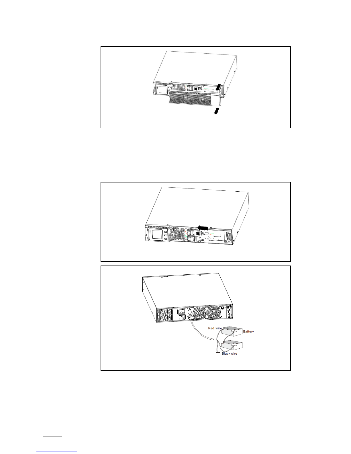
①Remove the front cover of each UPS, hold and extract the right cover part (without LCD) from the
panel (see fig. 7).
②Connect the internal battery connector red to red (see fig. 8). Press the connector firmly in to ensure
a proper connection.
Remark: Note that the above steps ① and ② are only concerning the replacement of batteries or
the addition of internal batteries. If the UPS is delivered with installed internal batteries, then the
plug is already connected.
CAUTION: A small electric arc may occur when connecting the internal batteries. This is normal and
will not harm personnel. Connect the cables quickly and firmly.
③If you are installing EBPs, then read the following section «Connecting the Battery Packs (EBPs)»
before continuing with the UPS installation.
④Replace the UPS front cover: if EBPs are installed, verify if the EBP cable has been well routed
through the knockout-opening in the knockout metal sheet before replacing the cover. Afterwards,
mount back the cover.
Fig. 7 –Extract the UPS front cover
Fig. 8 –Connection of internal batteries of the UPS
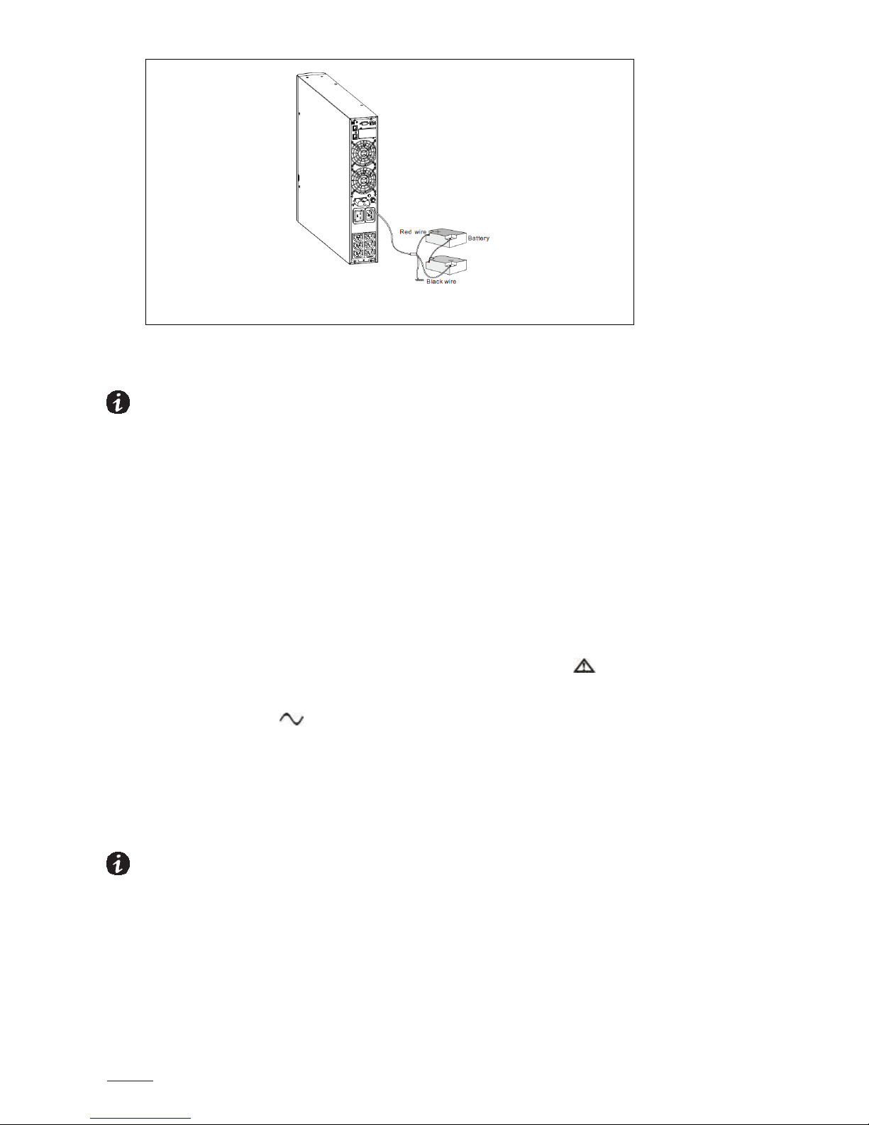
Fig. 9 –Connection of long backup external battery

SPIRIT G XL 1-3 KVA - PF0.9 -UPS www.visionups.com
11
⑤If you are installing a power management software, connect your computer to one of the
communication ports or optional connectivity card. For the communication ports, use an
appropriate cable.
⑥If your rack has conductors for grounding or for bonding of ungrounded metal parts, then connect
the ground cable (not supplied) to the ground bonding screw. See «Rear Covers» for the location
of the ground bonding screw for each model.
⑦If an emergency power-off (disconnect) switch is required by local codes, see «Remote Emergency
Power-Off (REPO)» to install the REPO switch before powering on the UPS.
⑧Continue under section «UPS Initial Start-up».
3.5. Connecting the Battery Packs (EBPs)
Follow these steps to install the battery packs (EBPs) for a UPS:
①Remove the front cover of each EBP and of the UPS (see fig. 11) as explained in section «Installation
of the UPS».
②Remove the small cable knockout metal sheet on the lower border of the UPS front cover, which is
intended for the EBP cable passages (see fig. 12).
③For the undermost EBP –as well as for a single battery pack -, remove also the small knockout metal
sheet on the upper border of the front cover. And if you are installing more than a single battery
pack (EBP), then remove for each additional pack this knockout metal sheet on the upper and lower
border of the front cover (see fig. 13 for the location of the knockouts for the EBP cable passages
coming from above). Except the lower metal sheet of the last pack does not have to be removed.
Fig. 10
Fig. 11 –Removing the EBP front cover
Fig. 12 –Removing the small knockout metal sheet for passing the cables

SPIRIT G XL 1-3 KVA - PF0.9 -UPS www.visionups.com
12
CAUTION:
A small electric arc may occur when connecting the internal batteries (EBP) to the UPS. This is normal and
will not harm personnel. Connect the cables quickly and firmly.
④Plug the EBP cable(s) into the battery connector(s) (see fig. 13). Up to four EPBs may be connected
to the UPS. Connect black to black. Press the connector tightly together to ensure a proper
connection.
⑤To connect a second battery pack (EBP), unclip the EBP connector on the first EBP and pull gently
to extend the wiring to the EBP connector on the second EBP. Repeat for additional EBPs.
Verify that the EBP connections are tight and the adequate bend radius and strain relief exist for
each cable.
⑥Replace the EBP front cover after verifying that the EBP cables are correctly routed through the EBP
cover knockouts and that the cover clips properly into the cover hooks on the left module side.
Repeat that for each additional EBP. Refer to «UPS Installation» for the installation of the front
cover.
⑦Ensure that all wires connected between the UPS and the EBP(s) are installed behind the front cover
and thus not accessible to users.
3.6. Rack mount converted to Tower Installation
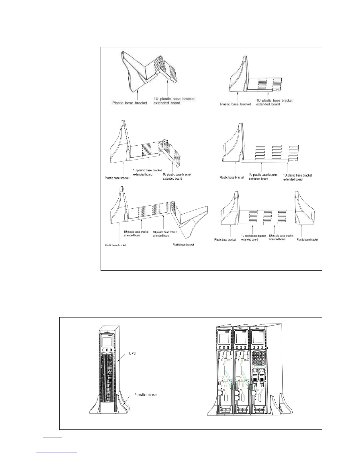
3.6.1. Rack mount converted to Tower by plastic base installation
For simple upright placing of the device, mount the plastic holders as follows:
① Nest the two plastic brackets as on fig. 14.
② Flatten the nested part.
Fig. 14 –Assembly of the plastic holder
SPIRIT G XL 1-3 KVA - PF0.9 -UPS www.visionups.com
13
③ Even when an EBP is needed to be placed in the middle, the assembly of the plastic holder stays
similar. The difference is that two extension pieces (1U) are added between the base brackets (see
fig. 15).
3.6.2. View of Tower Installation
The fig. 16-A shows one UPS in tower installation, and fig. 16-B shows the tower installation of UPS and battery packs
(EBPs). Install the base and then place the RT UPS one after another on the holders (see fig. 16-B). The cover
installation and the cable connection of the UPS and battery packs (EBPs) are the same as for RT.
③A ③B
③C ③D
③ E ③ F
Fig. 15 –Assembly of the plastic holder
Fig. 16-A –Tower installation of one UPS Fig. 16-B –Tower installation of UPS and battery packs
SPIRIT G XL 1-3 KVA - PF0.9 -UPS www.visionups.com
14
3.7. UPS Initial Start-up
NOTE: Before starting up, verify that the total equipment ratings do not exceed the UPS capacity in order to prevent
an overload alarm.
To start-up the UPS:
①If optional EBPs are installed, verify that the EBPs are connected to the UPS.
②Connect the equipment to the load to be protected, but do not turn on the protected equipment.
③It is necessary to make provisions for cord fastening and strain relief.
④Plug the detachable UPS power cord into the input connector on the UPS rear cover.
⑤Plug the UPS power cord into a power outlet. The display on front side illuminates.
⑥The UPS performs a self-test when starting. After that, the charger will charge the battery. If the output
displayed on LCD is «0», then there is no output. If you need output current without starting the UPS during
connection to the mains, then you need to set bPS option to «ON» in setting mode (refer to page 19 «Bypass
Mode Setting».
⑦Press the combination of start-up buttons on UPS front cover for at least ½ second. The UPS will start up
and the LED will turn on and off sequentially.
⑧Check the UPS front cover for active alarms or messages. Rectify any active alarms before continuing. Refer
for that on table 23 «Troubleshooting» on page 36. If the indicator is on, do not proceed until you have
removed all alarms. Check the UPS status on front cover to view the active alarms. Correct the alarms and
restart if necessary.
⑨Verify that the indicator is illuminated. It indicates that the UPS is operating normally and that any loads
are powered.
⑩If optional EBPs are installed, then refer to page 24 «Battery number configuration» to adjust the installed
number of EBPs.
⑪To change any other standard default factory settings, see on page 19 «Parameter Settings».
⑫If you installed an optional EPO, then test the EPO function: activate the external EPO switch. Verify the
status change on the UPS display. Deactivate the external EPO switch and restart the UPS.
a) NOTE: At initial start-up, the UPS sets the system frequency according to input frequency of the line (the input
frequency auto-sensing is enabled by default).
b) NOTE: At initial start-up, please set the needed output voltage before you are starting up the UPS. After the
subsequent start-up, the UPS will output the setting voltage.
c) NOTE: The internal batteries charge up to 80% of capacity in less than 5 hours. However, we recommend after
installation or long-term storage that the batteries are charged during 48 hours. If optional EBPs are installed, refer
to recharge times listed in table 21 «Battery runtimes at 100% load» on page 34.
Fig. 17 –Connection of long backup external battery

SPIRIT G XL 1-3 KVA - PF0.9 -UPS www.visionups.com
15
4. DISPLAY MONITOR, OPERATION AND CONTROL
This chapter contains information for use of the UPS, including front cover operation, operating modes, UPS start-up and
shutdown, transferring the UPS between the modes, configuring bypass settings, load segments and battery settings.
4.1. Control functions
The UPS has a LCD segmental display with three buttons and backlight. It provides useful information about the UPS itself,
load status, measurements and settings (see fig. 18).
TABLE 1 –Indicator descriptions
Indicator
Description
red
ON - The UPS has an active alarm or fault.
yellow
ON - The UPS is in bypass mode. The UPS is operating normally on bypass during ECO mode with high
efficiency operation.
yellow
ON - The UPS is in battery mode.
ON - The UPS is operating normally.
NOTE: When the UPS is powered on or is in start-up process, these indicators will turn on and off sequentially.
NOTE: On different operation modes, these indicators will indicate differently. Refer for that to table 7.
TABLE 2 –Button functions
Button
Function description
Start-up
combination
( + )
RT - Press and hold these keys longer than ½ second to turn on the UPS or to turn it off.
Rotating
combination
( + )
RT - Press and hold these keys longer than 2 seconds to circumrotate the LCD.
Battery
test/mute
combination
( + )
Press and hold these keys longer than 1 second in LINE mode or ECO mode: the UPS runs its self-test function.
Press and hold these keys longer than 1 second in battery mode: the UPS operates in mute function.
Scroll
or
Setting mode «without function»:
Press and hold this key longer than ½ second (but shorter than 2 seconds): indicates the items of LCD menu
orderly.
Press and hold this key longer than 2 seconds: indicates the items orderly and circularly (every two seconds);
when pressing and holding the key for some time again, it will return to the initial status.
Setting mode «with function»:
Press and hold this key longer than ½ second (but shorter than 2 seconds): select the set option.
Setting entry
Setting mode «without function»:
Press and hold the key longer than 2 seconds: function setting interface.
Setting mode «with function»:
Press and hold the key longer than ½ second (but shorter than 2 seconds): confirm the set option.
Press and hold the key longer than 2 seconds: exit from this function setting interface.
Fig. 18 –LED display functions

SPIRIT G XL 1-3 KVA - PF0.9 -UPS www.visionups.com
16
TABLE 3 –Operating status corresponding to indications
N
o
Operating status
Indication
Warning
Remarks
N
o
r
B
a
t
B
p
s
F
a
n
1
LINE mode
Voltage normal
●
none
Over- and undervoltage protection,
transfer to battery mode
●
●
★
every 4
seconds
2
Battery mode
Voltage normal
●
●
★
every 4
seconds
Battery voltage abnormal - warning
●
★
★
every
second
3
Bypass mode
Mains normal (AC) in bypass mode
●
★
every 2
minutes
Eliminate after starting the UPS.
Overvoltage of mains (AC), warning in
bypass mode
★
every 4
seconds
Undervoltage of mains (AC), warning in
bypass mode
★
every 4
seconds
4
Battery disconnect wanring
Bypass mode
●
★
every 4
seconds
Ensure that the battery disconnection switch is
closed.
Inverter mode
●
★
every 4
seconds
Ensure that the battery disconnection switch is
closed.
Mains connection or start
6 times
Ensure that the battery is connected properly.
5
Output overload protection
Overload, warning in LINE mode
●
★
2x per
second
Remove less important loads.
Overload in LINE mode, protection
●
●
long beeps
Remove less important loads.
Overload warning in battery mode
●
●
★
2x per
second
Remove less important loads.
Overload in battery mode, protection
●
●
●
long beeps
Remove less important loads.
6
Overload warning in bypass mode
●
★
every 2
seconds
Remove less important loads.
7
Fan fault (fan icon flashes)
▲
▲
▲
★
every 2
seconds
Check if the fan is e.g. blocked by an object.
8
Fault mode
●
long beeps
Contact service personnel if the fault code and
the symbol is displayed and if you can not
solve the problem by yourself.
Legend: ● The indicator lights for a longer period.
★The indicator flashes.
▲The indicator status depends on other conditions.
Explanatory note: If the UPS is in fault status, it is helpful to have the working status of the UPS and the detailed
information about the fault by means of the two below tables.

SPIRIT G XL 1-3 KVA - PF0.9 -UPS www.visionups.com
17
4.2. Display Functions
In case of a fault or after 5 minutes of inactivity, the LCD display shows the output parameters.
The backlit LCD dims automatically its lighting intensity after 5 minutes of inactivity. Press any button to restore the screen.
The LCD display comprises a numerical value section and graphical sections for capacity, fan status and charger status. For
more details, refer to table 4.
TABLE 4 –LCD display
Section
Description
Graphic
Numerical
value
section
Corresponds to the numerical value of the inquiring items (output, load,
temperature, input, battery). As adjacent graphic shows, the output voltage is
220V and the output frequency 50Hz.
Capacity
graphical
section
Graphical display of the capacity of battery and load. Each square represents 20%
of capacity. As the adjacent graphic shows, the load reaches 80%-100% (5
squares) and the capacity of battery is 40%-60% (3 squares). When the UPS is
overloaded, the icon will light. When the battery is weak or disconnected, the
icon will also light.
Fan status
graphical
section
Indicates graphically if the fan works normally or not. When it works normally, a
dynamic rotating fan blade will be shown. When the fan works abnormally, then
the icon lights as warning.
Charger
status
graphical
section
Graphical display of the charger status. When the charger works normally, then
the corresponding icon will vary dynamically and orderly. When the charger works
abnormally, then the icon remains flashing. When the UPS is in battery mode, the
number of icons of the charger status will vary according to the changeable
battery capacity (square).
SPIRIT G XL 1-3 KVA - PF0.9 -UPS www.visionups.com
18
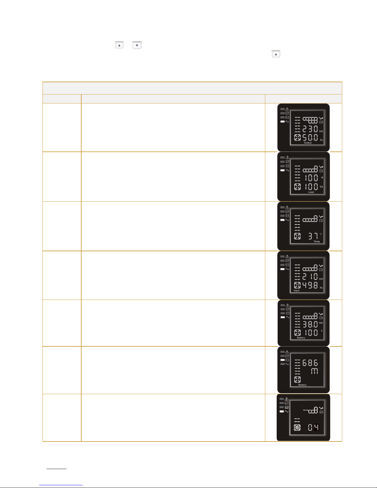
4.3. Parameters Inquiring
Press and hold the scroll key or longer than ½ second (but shorter than 2 seconds) to inquire about the items. The
inquired items include input, battery, output, load and temperature. Press and hold the key longer than 2 seconds and
the LCD begins to display the items circularly and orderly, transferring from one to another, every 2 seconds. Press and hold
the key again for some time, and it will return to initial status.
TABLE 5 –Parameters inquiring
Item
Description
Graphic
Output
Display of the output voltage and output frequency of the UPS. Adjacent graphic
shows an output voltage of 230V and an output frequency of 50Hz.
Load
Display of the numerical value of the active power (WATT) and the apparent
power (VA) of the load. As adjacent graphical example shows: the charge is 100
WATT and 100 VA (at disconnected load it is normal that the indicated
numerical value of WATT and VA is small).
Temperature
Display of the inverter temperature in the UPS. Adjacent graphic shows that the
temperature of inverter is 37°C.
Input
Display of the voltage and frequency of the input. The adjacent graphic shows
that the input voltage is 210V and the input frequency is 49.8Hz.
Battery
Display of the voltage and capacity of the battery. Adjacent graphic shows that
the battery voltage is 38V. The battery capacity is at 100% (it has been reckoned
approximately according to the battery voltage).
Remaining
battery
autonomy
Display of the remaining autonomy time of battery when the UPS operates in
battery mode. The number of minutes is from 0 up to 999. Adjacent graphic
shows the example of 686 minutes remaining for discharge.
System
Software
Version
Display of the system software version. Adjacent graphic shows that the system
software is the version 04.

SPIRIT G XL 1-3 KVA - PF0.9 -UPS www.visionups.com
19
4.4. Parameter Settings
The UPS has different setting functions. These settings can be done under any kind of UPS working mode. The applied settings
will take effect immediately if they correspond to standard guidelines. Below table describes how to set the UPS:
TABLE 6 –Parameter settings
Setting
function
(sequence
no.)
Setting procedure
Graphic
ECO mode
setting
① Enter the setting interface. Press and hold the function setting key longer
than 2 seconds to reach the setting interface. The letters «ECO» flash.
② Enter the ECO setting interface. Press and hold the function setting key
longer than ½ second (but shorter than 2 seconds). The letters «ECO» stop to
flash. The «ON» (or «OFF») below ECO flashes. Press and hold the scroll key
longer than ½ second (shorter than 2 seconds) to determine whether the
activation or deactivation of the ECO function.
③ Confirm the ECO selection. After selecting «ON» or «OFF», press and hold the
function setting key longer than ½ second (shorter than 2 seconds). The
setting of ECO function is completed now and the «ON» or «OFF» below «ECO»
lights without flashing.
④ If you choose «OFF», then continue at step 7, otherwise at step 5.
⑤ Set the ECO tolerance range. Press and hold the scroll key or longer
than ½ second (shorter than 2 seconds) to select the voltage range in percentage.
Select +5%, +10%, +15%, +25% (default is +25%). Then press and hold the function
setting key longer than ½ second (shorter than 2 seconds) to confirm the
selection.
⑥ Set the minus range in the same way.
⑦ After confirmation of the minus range, press and hold the function setting key
longer than 2 seconds to exit the setting menu.
Bypass
mode
setting
① Enter the setting interface. Press and hold the function setting key longer
than 2 seconds to reach the setting interface. Press and hold the scroll key
longer than ½ second (shorter than 2 seconds) to select bPS setting. The letters
«bPS» will flash.
② Enter bPS setting interface. Press and hold the function setting key longer
than ½ second (shorter than 2 seconds). The letters «bPS» stop flashing. The
«ON» (or «OFF») below bPS flashes. Press and hold the scroll key longer than
½ second (shorter than 2 seconds) to determine the activation or deactivation of
the bPS function.
③ Confirm the bPS selection. After selecting «ON» or «OFF», press and hold the
function setting key longer than ½ second (shorter than 2 seconds). The
setting of bPS function is now completed and the «ON» or «OFF» below «bPS»
lights without flashing.
④ If you choose «OFF», then continue at step 7, otherwise at step 5.
⑤Set the bPS tolerance range. Press and hold the scroll key or longer
than ½ second (shorter than 2 seconds) to select the voltage range in percentage.
Select +5%, +10%, +15%, +25% (default is +25%). Then press and hold the function
setting key longer than ½ second (shorter than 2 seconds) to confirm the
selection.
⑥ Set the minus range in the same way.
⑦ After confirmation of the minus range, press and hold the function setting key
longer than 2 seconds to exit the setting menu.
Output
voltage
setting
① Enter the setting interface. Press and hold the function setting key longer
than 2 seconds to reach the setting interface. Press and hold the scroll key
longer than ½ second (shorter than 2 seconds), select the function setting, choose
the interface for output voltage setting. The letters «OPU» will flash.
② Enter the output voltage setting interface. Press and hold the function setting
key longer than ½ second (shorter than 2 seconds). Then reach the setting
interface of output voltage OPU. The letters «OPU» will light for a long time. The
numerical value below «OPU» will flash. Press and hold the scroll key longer
SPIRIT G XL 1-3 KVA - PF0.9 -UPS www.visionups.com
20
than ½ second (shorter than 2 seconds), select the numerical value in accordance
with the «OPU» function. The provided voltages are 208V, 220V, 230V, 240V. You
can choose any of them by yourself (default is 220V).
③ Confirm the output voltage setting. After selection of the numerical value,
press and hold the function setting key longer than ½ second (shorter than 2
seconds). The setting of the OPU-function is completed now and the numerical
value below «OPU» lights without flashing.
④ Exit the setting interface. Press and hold the function setting key longer
than ½ second (shorter than 2 seconds), exit the setting interface and return to
main interface.
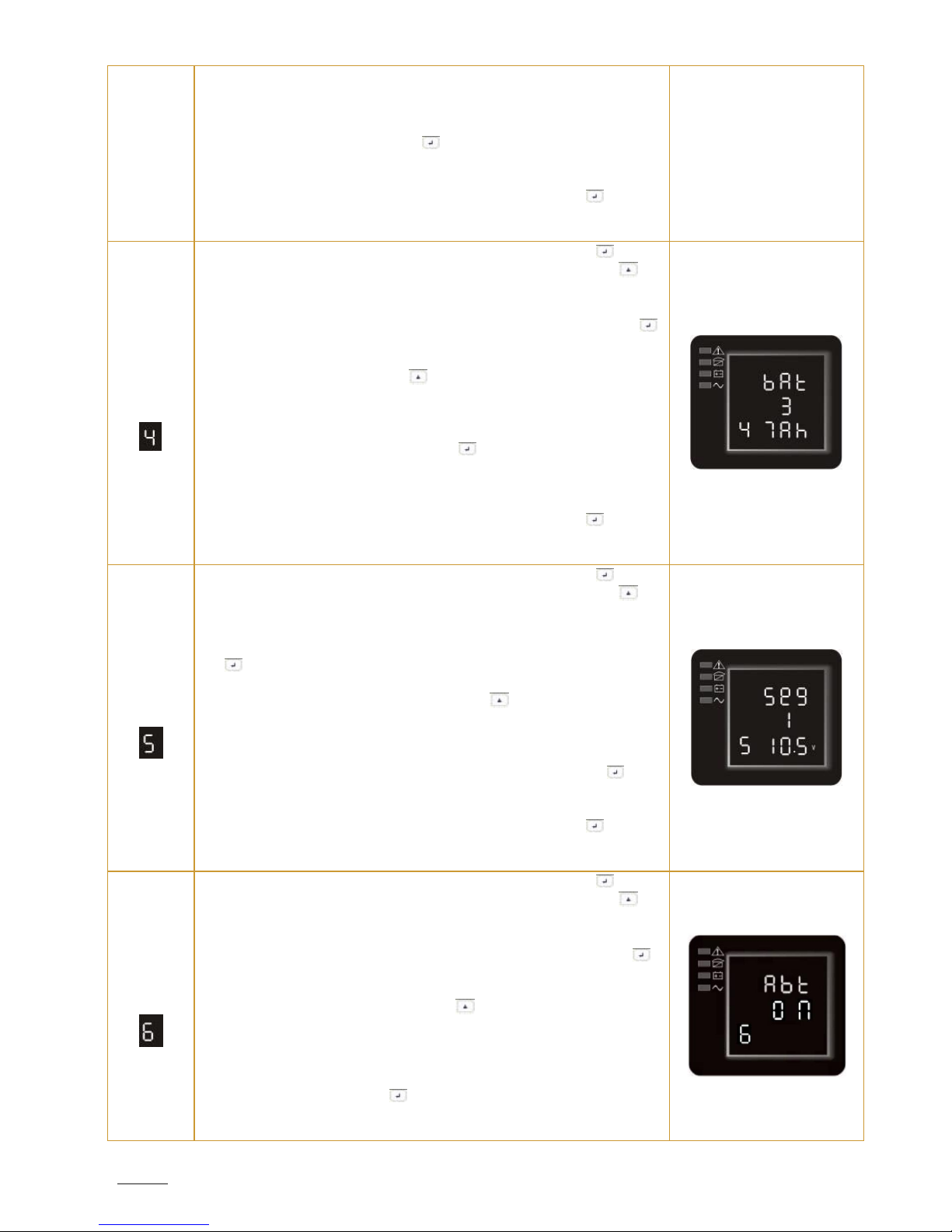
Battery pack
(EBP)
number &
type setting
① Enter the setting interface. Press and hold the function setting key longer
than 2 seconds to reach the setting interface. Press and hold the scroll key
longer than ½ second (shorter than 2 seconds), select the function setting, choose
the battery setting interface. The letters «bAt» flash.
② Enter the battery setting interface. Press and hold the function setting key
longer than ½ second (shorter than 2 seconds). Then reach the battery setting
interface. The letters «bAt» stop flashing. The numerical value below «bAt»
flashes. Press and hold the scroll key longer than ½ second (shorter than 2
seconds), select the numerical value in accordance with the real connected
battery strings.
③ Confirm the battery strings setting interface. After selection of the numerical
value, press and hold the function setting key longer than ½ second (shorter
than 2 seconds). Now, battery strings setting is completed and the battery
capacity value below will flash.
④ Set the battery type in the same way.
⑤ Exit the setting interface. Press and hold the function setting key longer
than ½ second (shorter than 2 seconds), exit the setting interface and return to
main interface.
Load
segment
setting
① Enter the setting interface. Press and hold the function setting key longer
than 2 seconds to reach the setting interface. Press and hold the scroll key
longer than ½ second (shorter than 2 seconds), select function setting, choose the
battery setting interface. The letters «Seg1» flash.
② Enter the load segment setting interface. Press and hold the function setting
key longer than ½ second (shorter than 2 seconds). Then reach the load
segment setting interface. The letters «Seg1» stop flashing. The numerical value
below «Seg1» flashes. Press and hold the scroll key longer than ½ second
(shorter than 2 seconds), select the battery voltage (10.5V, 11.0V, 11.5V –default
is 10.5V).
③ Confirm the battery voltage setting for the shutdown of segment. After
selection of the numerical value, press and hold the function setting key
longer than ½ second (shorter than 2 seconds). The battery voltage setting for the
segment shutdown is completed now.
④ Exit the setting interface. Press and hold the function setting key longer
than ½ second (shorter than 2 seconds), exit the setting interface and return to
main interface.
Automatic
battery test
setting
① Enter the setting interface. Press and hold the function setting key longer
than 2 seconds to reach the setting interface. Press and hold the scroll key
longer than ½ second (shorter than 2 seconds), select the function setting, choose
the automatic battery test setting interface. The letters «Abt» flash.
② Enter the «Abt» setting interface. Press and hold the function setting key
longer than ½ second (shorter than 2 seconds). Then reach the setting interface of
«Abt». The letters «Abt» light a long time. The word «ON» (or «OFF») below
«Abt» will flash. Press and hold the scroll key longer than ½ second (shorter
than 2 seconds) to determine the «Abt» function as used or as unused. If used,
the corresponding word is «ON», if unused the corresponding word is «OFF». It
can be determined by yourself.
③ Confirm the «Abt» setting interface. After selection of «ON» or «OFF», press
and hold the function setting key longer than ½ second (shorter than 2
seconds). Now, the «Abt» setting function is completed and the word «ON» or
«OFF» below «Abt» lights without flashing.
This manual suits for next models
7
Table of contents
Popular UPS manuals by other brands


Acumentrics
Acumentrics Rugged-UPS 2500 Series Operator's guide

MGE UPS Systems
MGE UPS Systems EXB 5 quick start

Sanyo Denki
Sanyo Denki S-A11KL202B0015SS 00 Series manual

AVIEM Systems
AVIEM Systems Spring MT 500 instruction manual

Huawei
Huawei PDU8000 Series Quick installation guide

SynQor Headquarters
SynQor Headquarters UPS-1500-S-2S Series Operator's guide

CyberPower
CyberPower BU600E user manual

Eaton
Eaton Power Xpert 9395 550/275 Installation and operation manual

Falcon
Falcon RACKMOUNT UPS PLUS FN3KRM-2 Owner's operating manual
 user manual")
AEG
AEG Protect C LCD 6000 (S) user manual

Toshiba
Toshiba Power Supply Specifications

Altronix
Altronix Maximal series installation guide