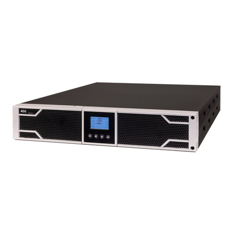
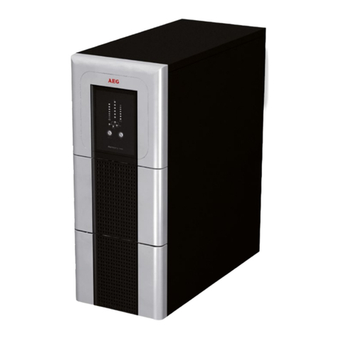
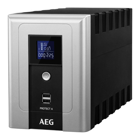
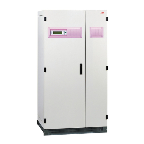
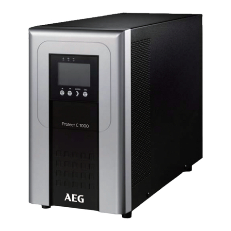
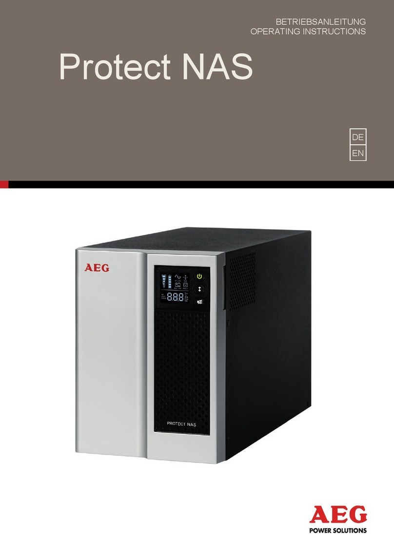
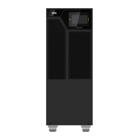
AEG Protect C LCD 6000 (S) User manual

PROTECT C
User Manual
Protect C LCD 6000 (S)
Protect C LCD 10000 (S)
Protect C LCD BP 6000
Protect C LCD BP 10000
EN

2
Status
Change
Date
Name
00
Created
18/03/2019
Smrekar
REVISION

3
Thank you for purchasing the AEG PS UPS Protect C LCD
from AEG Power Solutions.
Safety information and operating instructions are included in
this manual. To ensure correct use of the UPS, please read this
manual thoroughly before operating it. Use this manual properly.

4
1. NOTES ON THESE OPERATING INSTRUCTIONS ................................. 6
1.1 Duty to provide information ...................................................... 6
1.2 Operating instructions ............................................................... 6
1.3 Validity ...................................................................................... 6
1.4 Warranty and liability ................................................................ 6
1.5 Handling ..................................................................................... 7
1.6 Copyright ................................................................................... 7
2. SYSTEM OVERVIEW ........................................................................ 8
2.1 Technology ................................................................................. 8
2.2 System description ..................................................................... 9
2.3 Technical data .......................................................................... 11
3. SET-UP AND OPERATION .............................................................. 16
3.1 Unpacking and Inspection ........................................................ 16
3.2 Transportation to the site. ....................................................... 17
3.3 Point of installation .................................................................. 18
3.4 Overview: Connections, Operating / Display Elements ............ 20
3.4.1 Front panels ................................................................ 20
3.4.2 Rear panels ................................................................. 21
4. COMMISSIONING ......................................................................... 23
4.1 Protection for the personnel.................................................... 23
4.2 Mains connection general information .................................... 24
4.3 Mains connection .................................................................... 25
5. ELECTRICAL START UP ................................................................... 27
5.1 Operating modes ..................................................................... 27
5.1.1 Normal operation ....................................................... 27
5.1.2 Battery operation / autonomy operation ................... 27
5.1.3 Bypass operation ........................................................ 28
5.1.4 Manual bypass ............................................................ 29
5.1.5 Unit overload .............................................................. 29
5.2 Control panel ........................................................................... 30
5.3 LCD description ........................................................................ 34
5.4 Display functions ...................................................................... 37
5.5 User settings ............................................................................ 37
5.6 UPS startup and shutdown ...................................................... 39
5.6.1 Starting the UPS with utility ........................................ 39
CONTENT
S

5
5.6.2 Starting the UPS on Battery ........................................ 40
5.6.3 UPS shutdown with utility........................................... 40
5.6.4 UPS shutdown without utility ..................................... 41
5.7 LCD operation .......................................................................... 42
5.7.1 The main menu ........................................................... 42
5.7.2 The UPS status menu .................................................. 44
5.7.3 The measurement menu ............................................ 44
5.7.4 The event log menu .................................................... 45
5.7.5 The control menu ....................................................... 46
5.7.6 The identification menu .............................................. 48
5.7.7 The setting menu ........................................................ 49
6. COMMUNICATION PORTS ............................................................ 50
6.1 RS232 or USB communication ports ........................................ 50
6.2 Emergency Power Off .............................................................. 50
6.3 Dry input & Dry output contacts .............................................. 51
6.4 Intelligent Card (Optional) ....................................................... 51
6.5 UPS Management Software ..................................................... 52
7. TROUBLESHOOTING ..................................................................... 53
7.1 Silencing the alarm................................................................... 58
8. PARALLEL OPERATION .................................................................. 59
8.1 How to install a new parallel UPS system ................................ 59
8.2 How to join a new UPS to parallel system: .............................. 62
8.3 How to remove a single UPS from parallel system: ................. 63
8.4 How to remove all the UPS from parallel system .................... 64
9. MAINTENANCE ............................................................................. 65
9.1 Equipment care ........................................................................ 65
9.2 Storing the equipment ............................................................. 65
9.3 Replacing batteries .................................................................. 65
9.3.1 Replacing the External Battery Module ...................... 67
9.3.2 Testing new batteries ................................................. 68
9.4 Recycling the used equipment ................................................. 68
9.5 Disposal ........................................................................................
70
10. GLOSSARY .................................................................................... 71

6
1.1 Duty to provide
information
These operating instructions will help you to install and operate the
Uninterruptible Power Supply (UPS) Protect C series – safely and properly,
and for its intended purpose. These operating instructions contain
important information necessary to avoid dangers during operation.
Please read these instructions carefully prior to commissioning!
1.2 Operating instructions
The owner of this unit is obliged to communicate the full content of these
operating instructions to all personnel transporting or starting the Protect
C or performing maintenance or any other work on the unit.
1.3 Validity
These operating instructions comply with the current technical
specifications of the Protect C at the time of delivery. The contents do not
constitute a subject matter of the contract but serve for information
purposes only.
1.4 Warranty and liability
We reserve the right to alter any specifications given in these operating
instructions, especially with regard to technical data and operation, prior
to start-up or as a result of service work. Claims in connection with
supplied goods must be submitted within one week of receipt, along with
the packing slip. Subsequent claims cannot be considered.
The warranty does not apply to damage caused by non-compliance with
these instructions (such damage also includes damaging the warranty
seal). AEG will accept no liability for consequential damage. AEG reserves
the right to rescind all obligations such as warranty agreements, service
contracts, etc. entered into by AEG and its representatives without prior
notification in the event of maintenance and repair work being carried out
with anything other than original AEG spare parts or spare parts purchased
by AEG.
1.
NOTES ON THESE OPERA
TING INSTRUCTIONS

7
1.5 Handling
Protect C is designed and constructed so that all necessary steps for
start-up and operation can be performed without any internal
manipulation of the unit. Maintenance and repair work may only be
performed by trained and qualified personnel.
Illustrations are provided to clarify and facilitate certain steps.
If danger to personnel and the unit cannot be ruled out in the
case of certain work, it is highlighted accordingly by pictographs
explained in the safety regulations of chapter 3.
1.6 Copyright
© Copyright 2019 AEG Power Solutions GmBH, Warstein-Belecke,
Germany. All rights reserved.
This document must not be reproduced, either in whole or in part,
without the express permission of AEG Power Solutions GmBH.
AEG is a registered trademark used under license from AB Electrolux.
This product complies with the safety and environmental regulations in
EU.
If the time arises to throw away your product, please recycle all the
components possible.
Batteries and rechargeable batteries are not to be disposed in your
domestic waste! Please recycle them at your local recycling point.
Together we can help to protect the environment.

8
2.1 Technology
Protect C is an Uninterruptible Power Supply (UPS) for essential loads such
as PCs, workstations, servers, network components, telecommunication
equipment and similar devices.
It has the following model versions:
- Protect C 6000 LCD, 6kVA unit with integrated battery
- Protect C 6000S LCD, 6kVA unit with the bigger charger for long
backup
- Protect C 10000 LCD, 10kVA unit with integrated battery
- Protect C 10000S LCD, 10kVA unit with the bigger charger for
long backup
- Protect C 6000BP LCD, battery cabinet for 6kVA unit
- Protect C 10000BP LCD, battery cabinet for 10kVA unit
It consists of:
• Mains filter with overvoltage Protection (appliance Protection / class D)
• Rectifier section with PFC logic (power factor correction unit)
• Charger is buck topology from DC BUS
• Integrated sealed, maintenance-free battery system
(Protect C 6000 LCD / C 10000 LCD) as energy storage medium with
downstream DC/DC converter unit
• IGBT inverter for continuous supply of connected loads with sinusoidal
AC voltage
• Automatic electronic bypass (SBS = Static Bypass Switch) as additional
passive redundancy
• Manual bypass for maintenance and service purposes (with SBS
activation when activated)
• Digital signal processor control unit.
2.
SYSTEM OVERVIEW

9
2.2 System description
The UPS is connected between the public utility's mains and the loads to
be Protected.
The power section of the rectifier converts the mains voltage to DC voltage
for supplying the inverter. The circuit technology used (PFC) enables
sinusoidal current consumption and therefore operation with little system
disturbance. The charger is buck topology from DC bus.
The configuration of this charging REC means the harmonic content of the
charging current for the battery is almost zero, so the service life of the
battery is increased even more. The inverter is responsible for converting
the DC voltage into a sinusoidal output voltage. A microprocessor-
controlled control system based on pulse-width modulation (PWM) in
conjunction with digital signal processor technology and extremely quickly
pulsating IGBT power semiconductors of the inverter guarantee that the
voltage system on the Protected busbar is of the highest quality and
availability.
In the event of mains faults (e.g. current failures), the voltage continues to
be supplied from the inverter to the load without any interruption. From
this point onwards, the inverter draws its power from the battery instead
of the inverter. No switching operations are necessary; this means there is
no interruption in the supply to the load.

10
The automatic electronic bypass serves to increase the security of supply
further. It switches the public mains directly through to the load if there is
an inverter malfunction. As a result, the automatic bypass represents an
extra passive redundancy for the load.
The integrated manual bypass ensures in case of service and/or
maintenances a complete power supply of all connected loads. The
internal electronic circuit (with exception of the Protected manual bypass)
can be enabled by the input fuse.
The maximum security of supply for connected loads is achieved by
switching up to three Protect C UPS appliances parallel. The n+x
technology provides the highest possible availability by a single or double
redundancy. On the other hand, the power can be raised by using the
single redundancy. In case of no redundancy the highest power is reached
with the UPS. The relation between available power and active
redundancy is explained in the following table.
Parallel system with Protect C 6000 LCD.
Available po
wer
Number of UPS units
1
2
3
Active
redundancy
level
0
6 kVA
12 kVA
18 kVA
1
-
6 kVA
12 kVA
2
-
-
6 kVA
Parallel system with Protect C 10000 LCD.
Available power
Number of UPS units
1
2
3
Active
redundancy
level
0
10 kVA
20 kVA
30 kVA
1
-
10 kVA
20 kVA
2
-
-
10 kVA

11
2.3 Technical data
UPS MODEL LIST
Protect C 6000(S) LCD
6000VA / 6000W
Protect C 10000(S) LCD
10000VA / 10000W
Protect C 6000BP LCD
Battery pack for
Protect C 6000 LCD
Protect C 10000BP LCD
Battery pack for
Protect C 10000
LCD
WEIGHT AND DIMENSIONS
Protect C 6000 LCD
225x589x452 mm (WxHxD)
61
kg
Protect C 6000S LCD
225x353x452 mm (WxHxD)
14kg
Protect C 10000 LCD
225x589x452 mm (WxHxD)
7
1kg
Protect C 10000S LCD
225x353x452 mm (
WxHxD)
16kg
Protect C 6000BP LCD
225x589x452 mm (WxHxD)
111
kg
Protect C 10000BP LCD
225x589x452 mm (WxHxD)
11
5kg
ELECTRICAL INPUT
Selectable input Voltage range
208/220/230/240V
Voltage
at 100% Load
176~276Vac
Nominal frequency
50/60Hz
auto
-
sensing
Frequency range
40 Hz
–
70 Hz,
for
≤60% rated load
45 Hz
–
55 Hz (50Hz system)
54 Hz – 66 Hz (60Hz system)
for >60% rated load
Bypass voltage range
176~264 Vac (default)
Noise filtering
MOV for normal and common
mode noise
Input connection
Hardwired
Input cable
Not provided

12
ELECTRICAL INPUT CONNECTIONS
Protect C 6000 LCD
Nominal
Over load input current (maximum
charging current, low input voltage,
continuous over load)
230V / 31.2A
Up to 43A
Protect C 6000S LCD
Nominal
Over load input current (maximum
charging current, low input voltage,
continuous over load)
230V / 38.7A
Up to 53,4A
Protect C 10000 LCD
Nominal
Over load input current (maximum
charging current, low input voltage,
continuous over load)
230V / 49.9A
Up to 70.1A
Protect C 10000S LCD
Nominal
Over load input current (maximum
charging current, low input voltage,
continuous over load)
230V / 57.6A
Up to 79.3A
ELECTRICAL OUTPUT
Voltage regulation
Normal mode:
±
1%
Battery mode: ±1%
Efficiency
Normal mode:
> 98% (High Efficiency mode)
> 95%
Battery mode: > 93%
Frequency regulation
Normal
mode
: Sync with line ±10%
of nominal line frequency (outside
this range: ±0.1% of auto-selected
nominal frequency)
Battery mode: ±0.1% of auto-
selected nominal frequency
Nominal output
208V*, 220V, 230V, 240V (voltage
configurable)
6000/10000VA* 6000/10000W*
Frequency
50 or 60Hz, autosensing or
configurable as a frequency
converter
Output overload
100
-
105
%: no alarm

13
105
-
125
%
: load transfers to Bypass
mode after 10 minutes
Output overload (Bypass mode)
100
-
105
%:
no alarm
105-125 %: continue working and
alarm
125-150 %: UPS shuts down after
30s
Voltage waveform
Sinewave
Harmonic distortion
< 1%
THDV on linear load
< 5% THDV on non
-
linear load
Transfer time
Online mode: 0 ms (no break)
High Efficiency mode: 10ms
maximum (due to loss of utility)
Power factor
1
Load crest ratio
3 to 1
Output connection
Hardwired
Output cable
Not
provided
NOTE: * for 208V output, the load level will be derating to 90%.
ENVIRONMENTAL AND SAFETY
Certifications
EN 62040
-
1
IEC/EN 62040-2: Cat. C3
IEC/EN 62040-3
EN 60950
-
1
EMC (Emissions)*
Conduction C3 IEC/EN 62040
-
2
Radiation C3 IEC/EN
62040
-
2
EMC (Immunity)
IEC 61000
-
4
-
2, Level 3
IEC 61000-4-3, Level 3
IEC 61000-4-4, Level 4 (also on
signal ports), IEC 61000-4-5, Level 4,
Criteria B
IEC 61000-4-6, Level 3
IEC 61000-4-8, Level 4
IEC 61000
-
4
-
11
Agency markings
CE
Operating
temperature
0~40
℃
full load no derating
40~50℃ output power derating to
50% load, Charger current derating
50%
Storage temperature
-
15 to 40°C (32 to 104°F) with
batteries
-25 to 60°C (5 to 140°F) without
batteries

14
Transit temperature
-
25 to 55°C (
-
13 to
130°F)
Relative humidity
0 to 95% no condensing
Operating altitude
Up to 3,000 meters (9,843 ft) above
sea level with 10% derating per
1000m
Transit altitude
Up to 10,000 meters (32,808 ft)
above sea level
Audible noise
< 50 dBA at 1 meter
typical for 6kVA
models
< 55 dBA at 1 meter typical for
10kVA models
NOTE: * for output cable < 10m.
BATTERY
C
onfiguration
192
Vdc
,
16
x 12V,
9
Ah for
Protect C
6000 LCD
240Vdc, 20 x 12V, 9Ah for Protect C
10000 LCD
Fuses
100A for 10kVA models and BP
battery cabinets
Type
Sealed, maintenance
-
free, valve
-
regulated, lead-acid, with minimum
3-year float service life at 25°C
(77°F). Lifetime is reduced above 30
°C.
Monitoring
Advanced monitoring for earlier
failure detection and warning
Battery port
External ANEN
-
SA30 connector on
power module for connection to
E
xternal
B
attery
M
odule
E
xternal
B
attery
M
odule
battery
cable length
100
cm
COMMUNICATION OPTIONS
Communication bay
A
vailable independent
communication bay for connectivity
cards
Compatible connectivity cards
MODBUS card
NMC card
AS400 card

15
Communication ports
RS
-
232 (DB9): 2400 bps
USB 2.0: full speed
Dry out
2 pins jumper (normally closed)
Dry in
2 pins jumper (normally closed)
Emergency Power Off
3 pins jumper
(normally closed)

16
3.1 Unpacking and Inspection
It is recommended to move the equipment to the installation site by using
a pallet jack or a truck before unpacking. The system may be installed only
by qualified electricians in accordance with applicable safety regulations.
The cabinet is heavy, please install it with at least two peoples.
If any equipment has been damaged during shipment, keep the shipping
cartons and packing materials for the carrier or place of purchase and file a
claim for shipping damage. If you discover damage after acceptance, file a
claim for concealed damage.
Unpacking the unit in a low-temperature environment may cause
condensation occurred in and on the cabinet. Do not install the unit until
the inside and outside of the unit are absolutely dry (hazard of electric
shock). Remove the packing materials and lift the unit out with two people
at least.
UPS unit:
Battery cabinet:
3.
SET
-
UP AND OPERATION

17
Check the provided accessories
Verify that the following additional items are included with the unit:
Protect C
6000/10000 LCD
Protect C
6000/10000BP LCD
Battery power cable
S
USB cable
S
RS232 cable
O
Parallel cable
S
Dry
contractor
S
EPO contractor
A
Stabilizer bracket
S
S
User manual
S
O
S: standard configuration
A: assembled to unit
O: optional configuration
If you ordered other accessories, please contact with local sale center.
Notes:
The cabinet is heavy, please see spec weight provided on the carton/label.
Do not lift the unit’s front panel and rear panel.
Discard or recycle the packaging in a responsible manner or store it for
future use.
Packing materials must be disposed in compliance with all local regulations
concerning waste. Recycling symbols are printed on the packing materials
to facilitate sorting
3.2 Transportation to the site.
Please transport the UPS only in the original packaging (to protect against
shock and impact).

18
3.3 Point of installation
UPS unit
To keep air-flowing freely, it is recommended to keep a clearance with
500mm space both for front and rear side.
1. Place the unit on a flat, stable surface in its final location,
2. Install ‘Stabilizer bracket’ (optional): remove side’s screw from the unit,
then install ‘Stabilizer bracket’ to the unit.
3. Install the unit to a surface (optional): place 4pcs bolts (M8 is
recommended) to the final location previously, bolt’s position please refer
to below, then fix the unit to the bolts

19
External Battery Module unit
NOTE: The Protect C 6000/10000BP LCD cabinets are referred to as
External Battery Module.
1. Install the External Battery Module model----Refer to UPS model
installation as above.
2. Connect External Battery Module to UPS with ‘Battery power cable’.

20
3.4 Overview: Connections,
Operating / Display
Elements
3.4.1 Front panels
Protect C 6000 /10000 LCD Protect C 6000S /10000S LCD,
long backup version
This manual suits for next models
3
Table of contents
Other AEG UPS manuals

AEG
AEG Protect alpha. 1200 User manual

AEG
AEG Protect C.R User manual

AEG
AEG PROTECT 1 LCD User manual

AEG
AEG Protect B. 750 PRO User manual

AEG
AEG PROTECT A. 500 User manual

AEG
AEG PDU 10-1 User manual

AEG
AEG PROTECT B. 2000 User manual

AEG
AEG Protect D. 6000 (BP) User manual

AEG
AEG PROTECT 1 Series User manual

AEG
AEG PROTECT C Series User manual

AEG
AEG Protect A Series User manual

AEG
AEG Protect 1. M User manual

AEG
AEG Protect 3.M 2.0 User manual

AEG
AEG Protect A. 1000 User manual

AEG
AEG 600 KVA User manual

AEG
AEG IST7 User manual

AEG
AEG Protect D Series User manual

AEG
AEG UPS 10 kVA User manual

AEG
AEG Protect Home User manual

AEG
AEG PROTECT D LCD+ User manual