Vision Works VWIC700 User manual

7” Camera System
Owner’s manual
(VWIC700)
Warranty Information
Thank you for purchasing Vision Works camera system. We have taken great care to provide you with a top quality
product. Vision Works comes with a one year warranty that covers defective materials or workmanship, as long as no
wiring or parts are modified in any manner. If our product is found to be modified the warranty will be nullified.
Please read and follow the owner’s manual for installation and operation of your camera system.
Return Policy:
No merchandise should be returned to Vision Works for credit unless accompanied by a return authorization number from
our company. You will receive credit for the full amount of the return, if the merchandise is returned within 30 days of the
invoice date. Any merchandise that is not returned within 30 days of the invoice date is subject to a restocking fee of 15%.
Contact your Vision Works dealer for return information.
Merchandise that has been special ordered cannot be returned for credit. Non-stock items returned for credit will be
subject to vendor’s return policy.
Important!
1. To prevent short circuit, make sure that the system is not plugged in or receiving power while making system
connections. In the event of a system short circuit, replacement of the 3A fuse will be required. Fuses are
located under the threaded tip of the cigarette lighter, and inside the threaded barrel section of the RED 12volt
supply wire. Replacement fuses are not included with this kit.
2. To ensure that you do not drain your battery, it may be necessary to disconnect the cigarette adaptor when not
in use.
3. The camera is completely weatherproof but the monitor is NOT and should NOT be exposed to water. Please
ask about weatherproof monitors if you have no cab.

1
1.0 Specifications
Monitor Specifications Camera Specifications
Model
7”
Model
SONY
Screen Size
7 inch
Resolution
700 TVL
Aspect
Ratio
16:9
Lens
3.6 mm
Luminance
350cd/m2
No. of Pins
4
Resolution
800*R.G.B*480
Weatherproof
Rating
IP68
Audio &
Video
2 video/2 audio input (dual
channel, single image
display)
Low Temp
Rating
-20 C
-4 F
System
PAL & NTSC automatically
Magnet
Yes
Voltage
12V-24V
Auto Shading
Yes
Language
Multi-language
OSD Menu
Display menu, brightness,
color, contrast adjustable
Built-in
Speaker
Included
Bracket
Accessories
U type bracket
Sunshade
Removable
Set Up
Mirror for individual image,
can set reserve trigger delay
in clock settings
2.0 Parts Identification
Monitor
Quantity 1
Camera with Magnet
Quantity 1
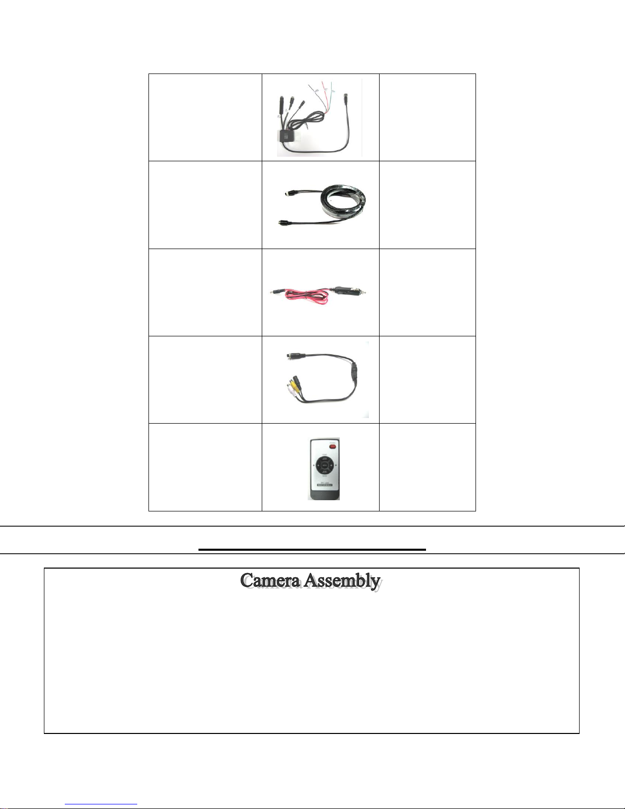
2
Main Harness
Quantity 1
Video Extension
Cable (30ft)
Quantity 1
Cigarette Lighter
Adapter
Quantity 1
AV Accessory Cable
Quantity 1
Remote Control
(CR2025 battery
included)
Quantity 1
3.0 Assembly Instructions
Camera can be mounted using magnet and attaching hardware. These are the steps required to attach the
magnet to the camera.
1. Position and align center hole of camera and bracket assembly on top of magnet.
2. Install bolt from underside of magnet and secure with flat washer and nut. Tighten this connection.
Tip: Although magnet contains 65lb pull force, it we recommend mounting your camera on a flat surface, and a zip
tie be used in addition to fasten the camera as a preventative measure in the event the camera is knocked off.
3
4.1 Installation Instructions:
1. Slotted holes of the universal base mount can be used to position and permanently attach the monitor
base to structure.
2. Installer must ensure that attaching hardware is suitable to support the weight of monitor and base.
3. Once the base has been fastened into position the monitor can be installed. Adjust monitor to desired
position and tighten the screws on the side of the monitor
4. Optional suction cup mounts are also available through your local dealer.
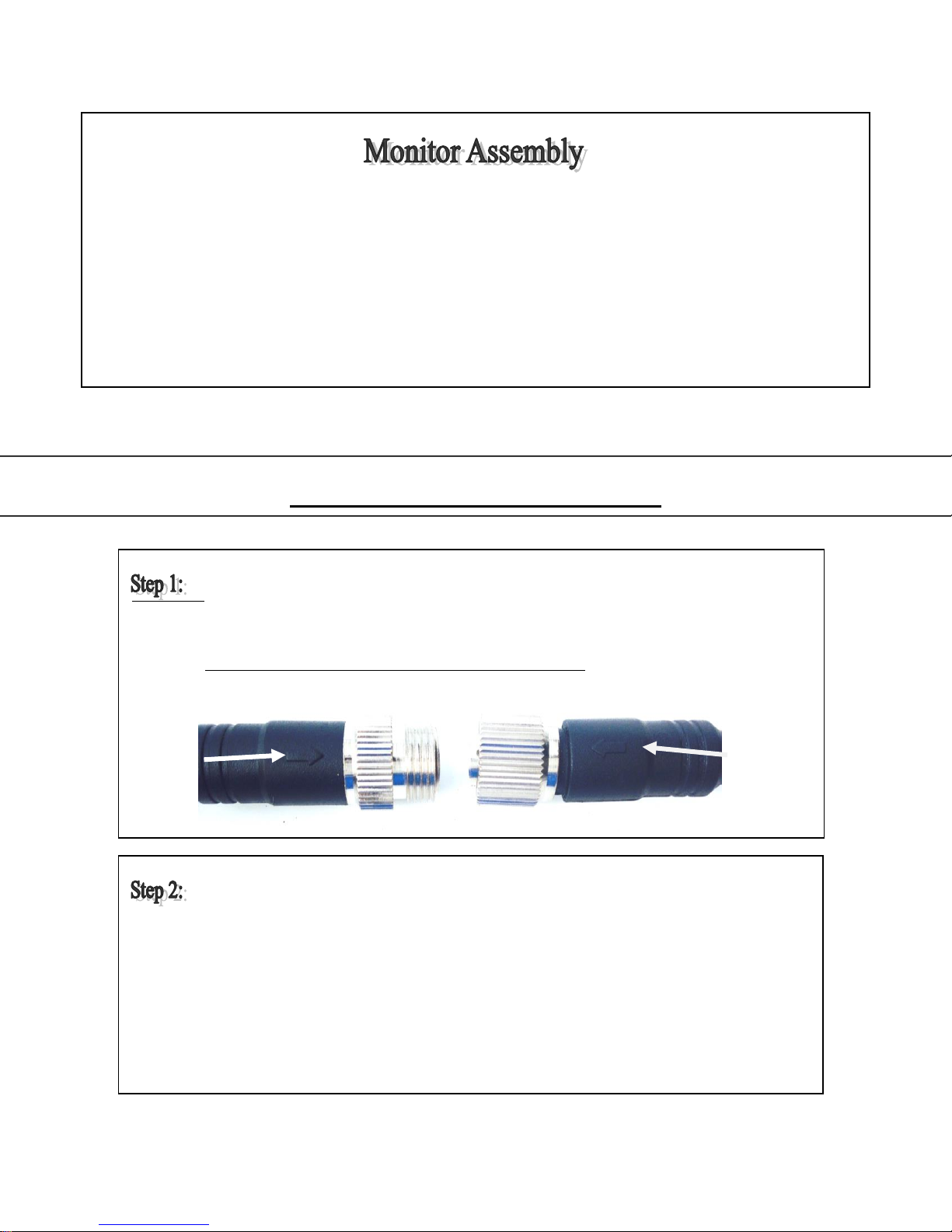
Connect MONITOR harness to the MAIN HARNESS MONITOR INPUT. Ensure arrows are aligned
on outer jacket of cable ends. Turn silver cable connector nut clockwise to secure connection of
the cables (IF YOU BEND THE PINS IT VOIDS THE WARRANTY). Ref. Picture Below & Fig.3
Connect VIDEO EXTENSION CABLE harness to C1 input on MAIN HARNESS.
Ensure arrows are aligned on outer jacket of cable ends.
Turn silver cable connector nut clockwise to secure the connection of the cables.
Do not over tighten. Pull rubber sleeve membrane over cable connection.
Ref. Fig.2

4
4.2 Power Cable Connection Installation:
Connect other end of VIDEO EXTENSION
CABLE harness to CAMERA harness
cable. Again, ensure arrows are aligned on
outer jacket of cable ends. Turn silver
cable connector nut clockwise to secure
the connection of the cables. Do not
overtighten.
Ref. Fig.2
The MAIN HARNESS included in this kit contains two video cable inputs. The cable input labelled C2 can be
used to accept a video signal from a second optional camera. C2 imaging can be selected from the remote
(Video Select) or monitor (V1/V2) controls. It will also activate and provide a video feed to the monitor if
12VDC power is supplied to the GREEN wire on the MAIN HARNESS.
Note: A common application for the C2 video feed is for rear view imaging when in reverse. For C2 video feed
for a reverse application, it is common to connect the GREEN wire to the reverse wire on the vehicle.
Ref. Fig.2
Included in kit is an AV Accessory Cable adaptor that will allow you to play videos from a DVD
player or alternate video source. It can be installed into C1 or C2 monitor inputs.
Cigarette Lighter Adapter - system can be powered by connecting the MAIN HARNESS CIGARETTE
LIGHTER INPUT to the mating connector of the CIGARETTE LIGHTER ADAPTER. The cigarette lighter
adapter can now be installed into a 12VDC power source. To verify that the system is receiving power, cup
your hands over the camera lens, and the LED lights will have a red glow. Ref. Fig.2
5
5 Operating Instructions:
Hardwire Option: - Connect BLACK wire of MAIN HARNESS to ground. Connect RED wire of MAIN
HARNESS to 12VDC power supply. To verify that the system is receiving power, cup your hands over the
camera lens, and the LED lights will have a red glow. The green wire is only used if you want the C2 input to
automatically display when the vehicle is put into reverse. If this is your preference please attach this wire to
the appropriate connection on your vehicle. Ref. Fig.2
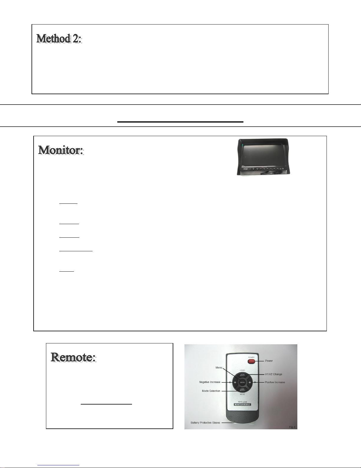
Ref. Figure >
Power Button –press to power on/off monitor and camera system.
Menu Button –press simultaneously to adjust Picture, System, Volume, Mirror Image, Clock/Trigger
Delay. Menu options will disappear 5 seconds after menu button is pushed. Ref. Fig.3
Picture - use AV button and + / - buttons to adjust brightness, contrast, color, and tint. Picture reset
can also be selected to reset picture to factory default settings.
System - use AV button and + / - buttons to adjust language, rotation, and system settings.
Volume - use + / - buttons to adjust monitor volume.
Mirror Image - use AV button to select Mirror option and + / - buttons to activate/deactivate mirror
image.
Clock - use AV button to select camera and + / - buttons to increase/decrease delay time of image
when the trigger wires are used in the system.
Mode Button –used to quickly alter the display for different pre-set brightness and contrast settings. When
you plug a second camera into the monitor harness…you can chose CH1 or CH2 for the camera that you
want displayed on the screen
Reverse Screen - To reverse image on screen press menu button until TCON is displayed. Press the up or
down button (this is a useful function when you want to mirror or un-mirror the image on the screen).
Note: Battery Protective Sleeve must be
removed prior to use.
Reference Monitor Functions in chapter
4.5 for definitions of Remote Control
button commands. Ref. Fig.4
Table of contents


