2
Table of Contents
Chapter 1 Introduction . . . . . . . . . . . . . . . . . . . . . . . . . . . . . .. . . . . . . . . . . . . . . . . . . . . . . . . 4
1.1 Key Features . . . . . . .. . . . . . . . . . . . . . . . . . . . . .. . . . .. . . . . . . . . . . . . . . . . . . . . . . . .. . . 4
1.2 .Technical Specifications . . . . . . . . . . . . . . . . . . . . . . . . . . . .. . . . . . . . . . . . . . . . . . . . . . . . . 4
1.3 .Hardware Overview . . . . . . . . . . . . . . . . . . . . . . . . . . .. . . . . . . . . . . .. . . . . . . . . . . . . . . . . . 5
1.3.1 Front Panel . . . . . .. . . . . . . . . . . . . .. . . . . . . . . . . . . . . . . . . .. . . . . . . . . . . . . . . . . . . 5
1.3.2 Back Panel . . . . . .. . . . . . . .. . . . . . . . . . . . .. . . . . . . .. . . . . . . . . . . . . . . . . . . . . . . . . 6
Chapter 2 Quick Install. . . . . . . . . . . . . . . . . . . . . . . . . . . . . . . . . . . . . . . . .. . . . . . . . . . . 7
2.1 Unpacking . . . . . . . . . . . . . . . . . . . . . . . . . . . . . . .. . . . . . . . . . .. . . . . . . . . . . . . . . . . . . . . . . . . . .7
2.2 The Procedure of Connection . . . . . . . . . . . . . . . . . . . . . . . . . . . . . . . . . . . . . . . . . . . . . . . . . . . . . . . .7
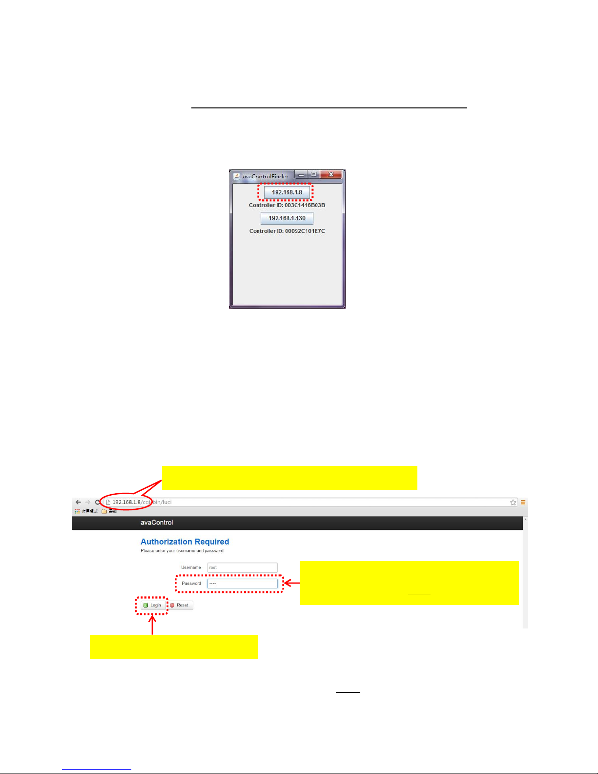
2.3Find the IP address of your
ZA1002US-5 . . . . . . . . . . . . . . . . . .. . . . . . . . . . . . . . . . . . . . . . .. . . . .. . . . .8
2.4 Setup Wi-Fi for your
ZA1002US-5. . . . . . . . . . . . . . . . . .. . . . . . . . . . . . .. . . . . . . . . . . . . . . . .. . . . .. . . . .8
2.4.1 System. . . . . . . . . . . . . . . . . .. . . . . . . . . . .. . . . . ... . . . . ... . . . . .. . . . . . . . . . . . .. . . . .. . . . .9
2.4.2 Network. . . . . . . . . . . . ... . . . . ... . . . . ... . . . . . . . . . .. . . . . . . . . . . . . . . . . . . . . . .. . . . .. . . . .10
2.4.2.1 General Setup. . . . . . .. . . . . ... . . . . . . . . . . . .. . . . . . . . . . . . . . . . . . . . . . .. . . . .. . . . .10
2.4.2.2 Advanced Settings. . . . . . . . . . . . . . . . . ... . . . . .. . . . . . . . . . . . . . . . . . . . . . .. . . . .. . . . .11
2.4.2.3 Physical Settings. . . . . ... . . . . ... . . . . ... . . . . .... . . . ... . . . . ... . . . . ... . . . . ... . . . ..12
2.4.2.4 Firewall Settingsb. . . ... . . . . ... . . . . ... . . . . ... . . . . ... . . . . ... . . . . ... . . . . ... . . . . ..12
2.4.3 Zwave. . . . . ... . . . . ... . . . . ... . . . . ... . .... . . . . ... . . . . ... . . . . ... . . . . ... . . . . ... . . . . ..13
2.4.4 Logout. . . . . . . . . .. . . . . . . . . .. . . . . . . . . .. . . . . . . . . .. . . . . . . . . .. . . . . . . . .. . . . . . . . . 13
2.5Initial setup procedure for ZA1002US-5 web
configuration . . . . . . . . . . .. . . . . . . . . . . . . . .. . . .. . . . .14
Chapter 3 Full web configurations . . . . . . . . . . . . . . . . . . . . . . . . .. . . . . . . . . . . . .. . . . . . . .15
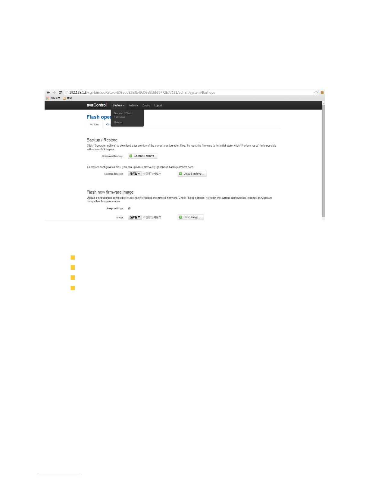
3.1 Enter web configure page . . . . . . . . . . . . . . . . . . . . . . . . . . . . . . . . . . . . . . . . . . . . . . . . . . . . 15
3.2 SetZwave– Z-Wave device settings . . . . . . . . . . . . . . . . . . . . . . . . . . . . . . . . . . . . . . . . . . . 17
3.2.1 The Z-Wave device configuration . . . . . . . . . . . . . . . . . . . . . . . . . . . . . . . . . . . . . . . . . . 17
3.2.1.1 Add a Z-Wave device . . . . . . . . . . . . . . . . . . . . . . . . . . . . . . . . . . . . . . . . . . . .. 17
3.2.1.2 Remove a Z-Wave device . . . . . . . . . . . . . . . . . . . . . . . . . . . . . . . . . . . . . . . . . . 19
3.2.2 Z-Wave Control and Log . . . . . . . . . . . . . . . . . . . . . . . . . . . . . . .. . . . . . . . . . . . . . . . .21
3.2.3 Topology . . . . . . . . . . . . . . . . . . . . . . . . . . .. . . . . .. . . . . . . . . . . . . . . . . . . .. . . . . . . . 22
3.2.4 Door Lock Security . . . . . . . .. . . . . . . . . . . . . . . . . . .. . . . . . . . . . . . . . . . . . . . . . . . . .23
3.2.5 Version Information . . . . . . . . . . . . . . . . . . . . . .. . . . . . . . . . . . . . . . . . . . . . . . . . . . . . 24
3.3 Room Setting . . . . . . . . . . . . . . . . . . . . . . . . . . . . . . . . . . . . . . . . . . . . . . . . . . . . . . . . . . . . 25