VisionTrack VT4000GE User manual

VER 1.0.0 1st Edition
VT4000
3G ENABLED VEHICLE RECORDER
USER GUIDE
• Thank you for purchasing the VT4000 Vehicle Recorder.
Model: VT4000GE (with 3G module for WCDMA
Band1(2,100MHz)/Band8 (900MHz))
Model: VT4000B (without 3G module)
• Please ensure that you read and understand this USER GUIDE
and use it before connecting and installing this Recorder.
• Please store the USER GUIDE in an easily accessible
location.

2
SAFETY ADVICE
GPS RECEPTION
CONTENTS
INTRODUCTION
FUNCTIONS
LEDS & BUZZER SPECIFICATION
INSTALLATION
OPERATION – ON SCREEN DISPLAY
AXIS ADJUSTMENTS BY DEVICE POSITIONS
CONFIGURATION TOOL USER GUIDE
SOFTWARE INSTALLATION
INITIALIZE SD CARD
DEVICE SETTINGS
RECORD SETTINGS
EVENT SETTINGS
SYSTEM SETTINGS
NETWORK SETTINGS
DMS5 SETTINGS
SOFTWARE USER GUIDE
PC VIEWER SOFTWARE SETTINGS
OPEN THE SD CARD
OPEN FILES
PLAYBACK
DRIVE DATA
TRACKING MAP
EVENT SEARCH
PRIVACY SETTINGS
SAVE JPEG AND MP4 FILE
PRINT IMAGE
BACKING UP FILES
BACKUP DATA LIST AND EXPORT
SPECIFICATION
APPENDIX RECORDING TIME TABLE
APPENDIX UPGRADE
TECHNICAL SUPPORT AND WARRANTY
INDEX
3
4
5
6
8
11
12
13
14
17
18
19
20
21
23
25
26
19
28
30
31
32
33
35
36
37
38
39
40
41
42
43
44
45
46

3
CAUTION
Damages due to production malfunction, loss of data, or other damages occurring
while using this product shall not be the responsibility of the manufacturer.
Although the product is a device used for recording videos, the product may not save
all videos in the caseof a malfunction. In the case of an accident, the sensor may not
recognize theshock when the impact is light and as a result it may not begin
recording automatically
.
SAFETY ADVICE
RISK OF ELECTRIC SHOCK
DO NOT OPEN
CAUTION: TO REDUCE THE RISK OF ELECTRIC SHOCK,
DO NOT REMOVE COVER.
NO USER-SERVICEABLE PARTS INSIDE.
REFER SERVICING TO QUALIFIED SERVICE PERSONNEL.
WARNING:
TO PREVENT FIRE OR ELECTRIC SHOCK HAZARD, DO NOT EXPOSE
THIS APPLIANCE TO RAIN OR MOISTURE.
CAUTION
Install the product where it does not block driver’s visibility and where there is
no airbag installed. This could cause an accident or might injure passengers in
case of accident
Please make sure you follow the safety advice/instructions
given in the user guide.
CAUTION
RISK OF EXPLOSION IF BATTERY IS REPLACED BY AN INCORRECT TYPE.
DISPOSE OF USED BATTERIES ACCORDING TO THE INSTRUCTIONS.
Battery for RTC (Real Time Clock) inside
CAUTION

4
GPS RECEPTION
1. Activate the product in an area without large buildings to
improve GPS reception.
2. The temperature range for optimum operation of the
GPS receiver in your car is -10 ~50°C.
3. When using the product for the first time or after a long
period (more than three days), it may take a little longer to
recognize your current location.
It may take between five and thirty minutes to get GPS reception.
GPS reception may be impaired under the following circumstances
1) If there is an object at the end of the GPS antenna
2) If your vehicle has metallic elements on the windshields
3) If equipment generating electromagnetic waves that interfere with the GPS
signal is installed in the vehicle e.g.: Other GPS devices such as a certain
type of wireless activated alarms, MP3 and CD players and camera alarms
using GPS.
4)
If you are using a receiver connected by cable, electric interference can be
avoided by simply changing the location of the receiver (antenna).
5) On heavily overcast or cloudy days, if the vehicle is in a covered location
such as under a bridge or raised roadway, in a tunnel, an underground
roadway or parking area, inside a building or surrounded by high-rise
buildings.
6) If GPS signal reception is poor, it may take longer to locate your current
position when the vehicle is moving than when it is stationary.
The commercial purpose GPS has the average range error of more
than 15 meters and the range error could be more than 100 meters
due to environmental conditions like buildings, roadside trees etc.

5
CONTENTS
VT4000
Vehicle Recorder
Camera input cable
Remote Controller
(with double sidedtape)
Power Cable
GPS Antenna module
Wire Splice clip and Velcro Sticker
3G Antenna (only for VT4000GE)
Audio/Video out cable

6
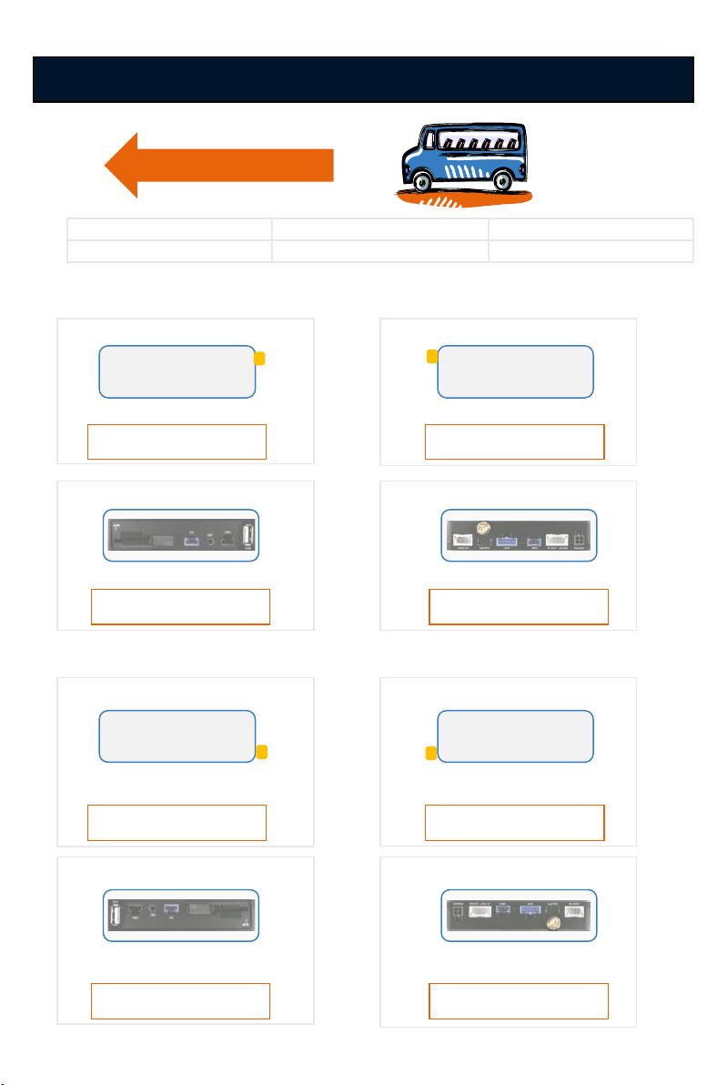
INTRODUCTION
Serial port
FRONT
REAR
SD Memory Card Slot
SD Locking Switch
External Microphone input
Debug port for
development
USB port for Wi-Fi dongle
Camera input
Remote Controller input
GPS inputUSB to Serial input
Audio/Video output &
Speed, RPM, Alarm inputs
Power input
3G antenna connector
(Only for VT4000GE) Internal Microphone
&Buzzer

7
INTRODUCTION
REMOTE CONTROLLER
M2 BUTTON M1 BUTTON
PANIC
BUTTON
POWER CABLE
Green LED (Network)
Blue LED (Record)
Red LED (Warning)
Black (Ground)
Red (Power Battery +)
White (Power ACC + )
Blue (Speed)
Brown (Alarm out2 ), Low(0V) to High (5V)
3 x Black (Ground)
Orange (Alarm out1 ), Low(0V) to High (5V)
ALARM IN/OUT CABLE
White (Alarm In1 , Voltage on/o(3~70V))
Green (Alarm In3, Voltage on/o(3~70V))
Gray (RPM)
Purple (Alarm In2, Voltage on/o(3~70V))

8
FUNCTIONS
Automatic Booting
Make sure the main unit and all components are properly connected.
Once the VT4000 has been wired to your car power source the VT4000 will
boot up, this will take around 30 seconds for the unit to be ready to record.
NOTE: The unit will not start recording immediately after power on. It takes
around 30 seconds for the built-in power backup system to charge.
Thereafter, the SD card will be ready to record.
NOTE: The DRV file consists of GPS and G-sensor data and it helps to find
specific data or driving behaviors. The DRV file overwrites the oldest data.
The DVR files will be made every 10 minutes.
Continuous Record (When Record mode set as “Continuous”)
This is the default mode for recording. In this setting the unit will begin
recording after boot up and record the entire time the unit is powered.
The resolution and frame rates can be set as per your requirements. You can
change the configuration of the recording using the VT4000 configuration
Tool. To do this, please see the ‘Settings’ section on page 21.
Event Record (When Record mode set as “Event”)
The unit will record when triggered by an impact(G-Sensor) or a push of the
‘PANIC’ button or Over speed or Alarm In1~3. Each event file contains up to 20
seconds prior & up to 20 seconds post event.
And the event file can be extended by 2nd trigger during event record.
When events are triggered continuously, for every event, 20 seconds post-re-
cording from the time of the event will be added to the event data file with a
maximum recording time of 3 minutes. When this 3 minutes is reached, the
file will be split and a new file will be created but the data will be continuous.
Dual Record (Continuous & Event Record)
The continuous record fps is 1fps and the file will be stored on the “Normal”
folder. Event record will work according to the fps setting for example
30frames per second recording and the file will be stored on the “Event”
folder.
DO NOT RECORD
The DRV (Drive Data) file will be recorded during driving at “Do Not Record”
mode. And the unit can send limited API like live track to Server.

9
FUNCTIONS
G-Sensor Calibration
1. Set G-Sensor Axis using the configuration tool.
2. “selfadj.ini”should be in the config folder of the SD card.
3. Install the unit and park the vehicle on a flat surface .
4. Turn on the unit and wait until it starts recording.
5. Press and hold the “M1”button more than 2 seconds.
6. You will hear “beep”when you press the “M1”button and then
you will hear another “beep”after 2 seconds. Then release the “M1”button.
7. Then calibration will be done within 2 seconds.
Built-in power backup (Super Capacitor)
When power to the unit is interrupted,VT4000 creates the last
file using the internal Super Capacitor.
Time and Date
Set your time zone using the configuration tool then VT4000 get’s the time
from the GPS satellite's.
SD Memory CardFormat
Please format [initialize] the SD card using the “Configuration Tool VT4000”
software.
G-Sensor Calibration is needed after installing theVT4000.
power and then check the BLUE LED light. Once the LED light
Power othe vehicle and take out SD memory card
Turn othe
is not on, you can now safely remove the SD memory card.
SAFELYREMOVE SDCARD

10
FUNCTIONS
Parking Mode Recording
Live Screening
To optimize use and prolong life of your SD cards please follow the below
instructions.
PRECAUTIONS FOR SD CARDS
Delayed Power Shutdown
With parking mode activated and on normal recording mode, the VT4000 will
change to parking mode when the vehicle is not moving for more than 5
minutes, recording at 1fps.
With an external monitor attached, the VT4000 oers the option to screen
video live.
Control the duration of time using the configuration tool. VT4000 stays
powered and recording/networking after shutdown.
1. Use only compatibly tested SD cards.
2. Only use dry and clean SD cards.
3. Format SD cards at least once every month or when the SD card seems
corrupted. This will wipe all data, images, and file names on the card
reducing recording errors.
4. Insert or remove SD cards only when the device is completely powered
o. Wait until the blue LED is completed o before removing SD card.
5. SD cards used for continuously recording equipment such as a drive
recorder typically lasts only 6-12 months.Change SD cards
periodically.

11
LEDS & BUZZER SPECIFICATION

12
INSTALLATION
Park your vehicle on a flat level surface.
Turn othe engine before installing the VT4000.
1) Find installation location for VT4000 like in the glove box,
under dash or trunk.
2) Use provided velcro adhesive to secure VT4000 recorder. Velcro can be
attached and detached freely.
NOTE: The adhesive will not stick well with dust or oil, etc.
Please make sure the surface is clean before applying.
3)
INTERIOR CAMERA
EXTERIOR CAMERA
4) Install the remote controller onto dash within reachof the driver using
provided double side tape.
5) Arrange the power cable neatly alongside of the windshield and door pillar
trim.TheVT4000 requires a continuous 12/24volt power source from the
vehicle.
Connect the “Red cable (Battery+)” to a fuse. It should be connected to a fuse
that has power all the time from car battery. And the “White cable(AC-C+)”
should be connected to a fuse that has power when you start the engine. The
ground cable should be contacted at the car body or battery negative.
Start on the car after installation.
Install the cameras (sold separately) with double side tape to the
windshield or other flat surfaces as been below. Adjust camera view.
Make sure the lens has an unobstructed view.

13
OPERATION–ON SCREEN DISPLAY
The following displays canonly be seen when a monitor is connected.
4CAMERAS(2x2) CAMERA1 CAMERA2 CAMERA3 CAMERA4
The default display is 2x2 with all cameras shown, to change, press
[M2] button to select which camera to view. Each press will change the
camera on display with the last option being all camera views.
14
AXIS ADJUSTMENTS BY DEVICE POSITIONS
Driving Direction
F: Front RR:Rear T:Top
B:Bottom R:Right-side L:Leftside
T
L
B
RRF
X: 0, Y: 0, Z:0
T
L
B
FRR
X: 0, Y: 0, Z:180
1) When device is in an upright position
T
F
B
LR
X: 0, Y: 0, Z:270
T
RR
B
RL
X: 0, Y: 0, Z:90
2) When device is in an upside down position
B
L
T
RRF
X: 180, Y: 0, Z:0
B
L
T
FRR
X: 180, Y: 0, Z:180
B
F
T
LR
X: 180, Y: 0, Z:270
B
RR
T
RL
X: 180, Y: 0, Z:90

15
AXIS ADJUSTMENTS BY DEVICE POSITIONS
3) When device is in a sideway position with the TOP to the left
R
L
RR
F
L
R
F
RR
X: 270, Y: 0, Z:0 X: 270, Y: 180, Z:0
F
RR
R
L
RR
F
L
R
X: 270, Y: 90, Z:0
4) When device is in a sideway position with the TOP to the right
L
R
RR
F
R
L
F
RR
X: 90, Y: 0, Z:0 X: 90, Y: 180, Z:0
F
RR
L
R
RR
F
R
L
X: 90, Y: 90, Z:0

16
AXIS ADJUSTMENTS BY DEVICE POSITIONS
5) When device is in a sideway position with the TOP facing front
L
R
B
T
X: 90, Y: 0, Z:270
R
L
B
T
X: 270, Y: 0, Z:90 X: 180, Y: 90, Z:0
F
RR
B
TR
6) When device is in a sideway position with the TOP facing rear
R
L
T
B
X: 270, Y: 0, Z:270
L
R
T
B
X: 90, Y: 0, Z:90 X: 0, Y: 90, Z:0
F
RR
T
BL
REMARK: Do no install the device with the Front facing down position.

17
CONFIGURATION TOOL USER GUIDE
Configuration Tool VT4000 Software
PC SYSTEM REQUIREMENT
If the PC does not meet the minimum system requirement, the
Configuration Tool Softwaremay not function properly.
OS Windows Vista. Windows 7, Windows 8/8.1
CPU Core 2 Duo 2.5GHz or Higher
RAM 2GB or Higher
Interface SD Memory Card Reader
HDD
Free space
Install : 55MB or Higher
Backup : 4GB or Higher
Display 1024 x 768 pixel/True Color or higher
Recommended PC specifications for Configuration Tool Software

18
1. Double click [setup.exe]
2. Select the language
3. Select destination location
4. Select Start Menu Folder then follow the dialog box prompts.
5. The “Configuration Tool VT4000” icon will be displayed on your desktop.
Please ask the Configuration Tool VT4000 Software to your distributor.
NOTE: To Un-install the Configuration Tool VT4000 Software
Make sure the program is not running and open the ‘Control Panel’ Select
‘Remove Program’ and remove the Configuration Tool VT4000 Software.
SOFTWARE INSTALLATION

19
Click!
INITIALIZE SD CARD
To initialize the SD card quickly, click on the above icon and you will be
presented with the following screen to choose the SD card to initialize. Click
‘OK’ when selected.
On the following screen, check the ‘Quick Format’ button and uncheck the
‘Keep current configuration files’ and Click ‘Start’ to begin initialization.

20
DEVICE SETTINGS
CAMERA CHECK BOX
Check all the cameras you wish to use.
CAMERA TITLE
Use the alphabet and numbers to rename (max 10 digits) the cameras. The
new names will be displayed on the all recordings.
VIDEO TYPE: Set the video type ”NTSC or PAL”
CAR PULSE TYPE: Select the vehicle’s car pulse type.
CAR PULSE STANDARD: Select the vehicle’s car pulse standard.
RPM TYPE: Select the vehicle’s RPM type.
G-SENSOR AXIS: Refer to page 14 in this manual and set Axis.
TV OUT: Check it to see live screen.
AUDIBLE CAMERA CHIME: Turn the Chime on or o
BUZZER ON: Turn the Buzzer on or o
SPEED SOURCE: Choose the speed source “GPS or Pulse” to use it on the unit.
DELAYED POWER SHUTDOWN: Set delayed power shutdown time.
This manual suits for next models
2
Table of contents
Popular Measuring Instrument manuals by other brands

TPI
TPI 621 instruction manual

Symmetricom
Symmetricom 4310 Operator's manual

Extech Instruments
Extech Instruments 461830 user manual

Zenner
Zenner zelsius C5 -ISF Installation and operating instructions

Swan Analytical Instruments
Swan Analytical Instruments AMI INSPECTOR Hydrogen Operator's manual

Perfect Prime
Perfect Prime TC0304 instruction manual


