manuals.online logo
Brands
  1. Home
  2. •
  3. Brands
  4. •
  5. SMC Networks
  6. •
  7. Measuring Instrument
  8. •
  9. SMC Networks IZH10 Series Manual

SMC Networks IZH10 Series Manual

ZH10-TFK19GB
Installation and Maintenance Manual
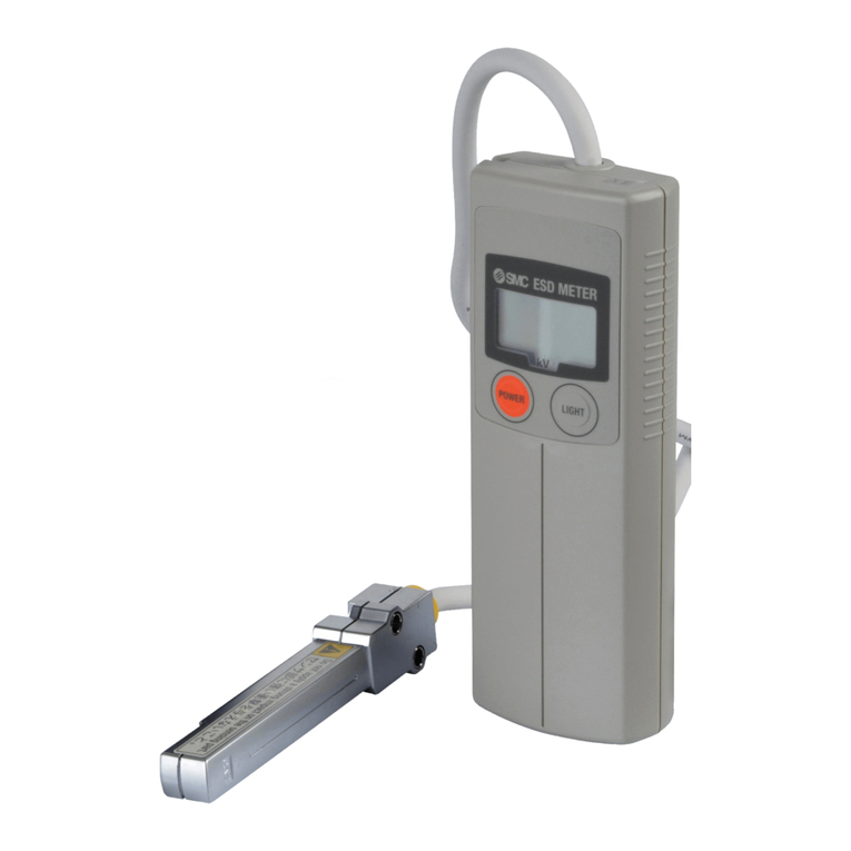
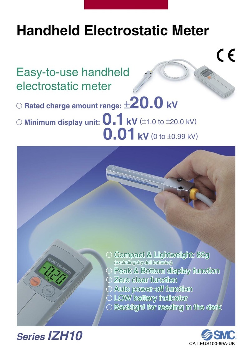
Handheld Electrostatic Meter
Type IZH10
Safety Instructions
• This manual contains essential information for the protection of users
and others from possible injury and/or equipment damage.
• Read this manual before using the product, to ensure correct
handling, and read the manuals of related apparatus before use.
• Keep this manual in a safe place for future reference.
• These instructions indicate the level of potential hazard by label of
"DANGER", "WARN NG" or "CAUT ON", followed by important safety
information which must be carefully followed.
• To ensure safety of personnel and equipment the safety instructions
in this manual and the product catalogue must be observed, along
with other relevant safety practices.
WARNING
• Do not disassem le, modify (including the change of a printed
circuit oard) or repair.
An injury or failure can result.
• Do not operate outside of the specification.
Fire, malfunction or damage can result.
Please confirm the specifications before use.
• Do not operate in an environment of flamma le, explosive or
corrosive gas.
Fire or an explosion can result.
The meter is not an explosion proof type.
• This instrument is supplied for the measurement of high voltage
up to ± 20 kV.
The user must take all necessary precautions to use it safely, as high
voltages are dangerous.
• Heavy impacts on the meter.
Do not drop, allow any collision or apply excessive shock to the meter
when handling. t can result in damage to the meter and accidents.
• Do not allow the sensor to come into contact with the
measurement target.
Failure and accidents may occur.
• Handling of ground wire.
To ensure safety and accurate measurements always use the ground
wire. f the ground wire is not connected properly, charge can
accumulate in the sensor and/or the ground terminal and then
discharge to operator. Handle the sensor and ground terminal
carefully.
Safety Instructions (continued)
NOTE
Follow the instructions given below when handling the meter.
f the instructions are not followed the meter may malfunction or become
damaged.
Notes for use
• Do not carry or swing the meter by the sensor cable. f the sensor cable
breaks, the meter can hit people or objects, causing injury or damage.
• Do not press setting buttons with sharp, pointed objects.
• Do not touch the detecting surface of the sensor by hand, directly or with
a metal object. Such action can result in damage and accidents as well
as a loss of specified function and performance.
• When measuring objects with a high charged potential, there is a risk of
electrostatic discharge to the hand of the user holding the sensor. n this
situation use the high voltage measuring handle (optional extra) and
wear protective rubber gloves. Starting from a safe distance, slowly move
the sensor closer to the measurement target. Stop immediately if the
display shows "HHH" or "LLL" as the charged potential is out of range.
This means the charged potential is very high, which can be highly
dangerous.
The display will not change if the sensor is moved closer to the charged
object.
• Do not place objects and cables other than the measurement target near
the detecting port of the sensor. Doing so will cause interference and
result in an inaccurate display reading.
• Handle cables carefully so they do not get tangled with userís equipment,
as this can be highly dangerous.
• The measurement distance is 50 mm. Refer to scales shown on the label
attached to the sensor.
• The meter is designed to measure static electricity and must not be used
for other purposes.
Environment for use/storage
• Do not use in areas where electromagnetic noise is generated.
t can result in malfunction (display of incorrect value), deterioration and
damage to internal components.
• Do not leave the meter in areas exposed to direct heat or sunlight, such
as inside a closed car or near a heating appliance. High temperatures
can cause deformation, discolouration and damage to the meter.
• Do not use in areas where the meter could be splashed by oil or
chemicals.
Maintenance and Other Precautions
• Use 2 of AA (LR6) alkaline dry cell batteries in the meter. Other batteries
are not suitable and their use may result in damage.
• When fitting the batteries pay particular attention to the polarity markings
("+" and "-") stamped on the body of the meter. f fitted incorrectly, the
batteries may leak or even burst.
• Remove the batteries when the meter will not be used for extended
periods.
• f the meter body becomes dirty, clean by wiping with a soft cloth.
For more stubborn dirt wipe with a cloth dampened with a dilute solution
of neutral detergent, then dry thoroughly with another clean, dry cloth.
Model Indication Method
Outline with Dimensions (mm)
Meter ody
Sensor
POWER
LIGHT
kV
BESTDETECTING POSITION 50mm
Do not apply a strong impact on the sensing part.
40 20 (5)
110
POWER
MeasuredPotential 20.0kV
BATTERY1.5V x 2 LR6
G
AUTOPOWER
-
OFFExtension
Press
for6sec
PEAK/ BOTTOM MODE Display
Normal Bottom
POWER POWER
Press! Press!
Peak
MADEIN JAPAN
Extendsat
15min
SMC
600
87.5
4.8
9
16.6
13
0.5
8.8
6.5
7
(7.5)
BEST DETECTING POSITION 50mm
2 3.4
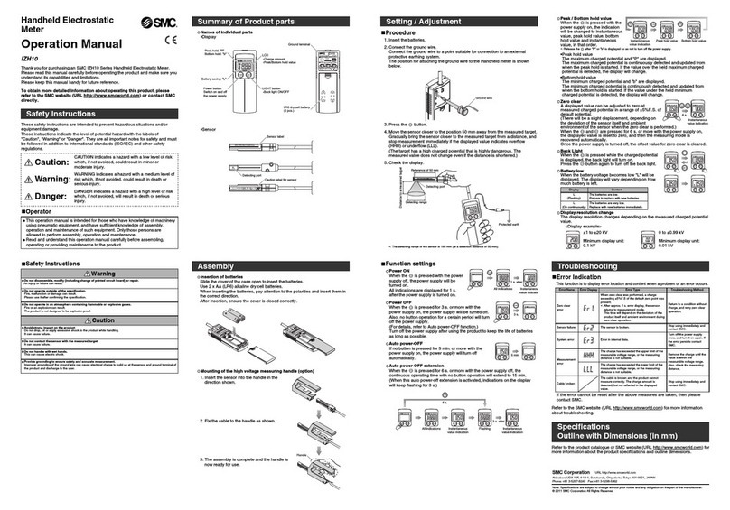
Names and Functions of Individual Parts
Meter ody
Sensor
kV
LCD
Charge amount
Peak / Bottom
hold value
LIGHT button
Backlight ON/OFF
AA (LR6) dry
cell battery
Battery saving: "L"
Peak hold: "P"
Bottom hold: "b"
POWER button
Power supply
ON/OFF
POWER
LIGHT
(2 pcs.)
POWER
Measured Potential 20.0kV
BATTERY1.5V x 2 LR6
G
AUTO POWER
-
OFF Extension
Press
for 6sec
PEAK / BOTTOM MODE Display
Normal Bottom
POWER POWER
Press! Press!
Peak
MADEIN JAPAN
Extendsat
15min
Ground terminal
BEST DETECTING POSITION 50mm
Caution label for sensor
Do not apply a strong impact on the sensing part.
Sensor label
Detecting port
Specification
Note 1) AA alkaline dry cell batteries (2 pcs.) are not included, and need
to be supplied separately.
Note 2) With 2 new alkaline dry cell batteries at room temperature.
CAUTION f instructions are not followed there is a
possibility of injury or equipment damage.
WARNING f instructions are not followed there is a
possibility of serious injury or loss of life.
DANGER n extreme conditions, there is a possibility of
serious injury or loss of life.
IZH10 -
Option
Symbol Contents
Nil None
H High voltage measuring handle
• Accessories and Options/Part Num er for Individual Parts
Description
Ground wire (1.5 m)
Soft case
High voltage measuring handle
Part number
ZH-A-01
ZH-B-01
ZH-C-01
*The ground wire and soft case are included with all products.
tem ZH10
Rated charge range +20.0 kV
Display resolution 0.01 kV (0 to +0.99 kV)
0.1 kV (+1.0 kV to +20.0 kV)
Measurement distance
50 mm
(between sensor and measurement
target)
Power supply Note 1)
1.5 V AA alkaline dry cell battery (2 pcs.)
(Battery life: >15 hours continuous use)
Note 2)
Display accuracy
Temperature
range
Humidity
range
Vibration
resistance
+5 %F.S. +1 digit
Operating: 0 to 40 oC,
Storage: -10 to 60 oC
(No freezing or condensation)
Operation and storage: 35 to 85 %R.H.
(No condensation)
10 to 150 Hz applied for 2 hours in each
direction of X, Y and Z with 1.5 mm
amplitude resistance and 98 m/s2
acceleration (with power OFF)
100 m/s2applied 3 times in each
direction of X, Y and Z (with power OFF)
Environmental
resistance
Enclosure P40
mpact
resistance
Material
Weight
Standard
Accessory
Meter body: PC/ABS, Sensor: ABS
85 g (excluding batteries)
CE marking
Ground wire, soft case
Power ON
When the "POWER" button is pressed with the meter off, the meter will
be turned on. All display segments are displayed for 1 second after the
meter is turned on.
Power OFF
When the "POWER" button is pressed for 3 seconds or more with the
meter on, the meter will be turned off. f no buttons are pressed for a set
time the meter will automatically turn off. (For details, refer to Auto
Power-off function.)
To conserve battery life turn the meter off immediately after use.
kV
POWER
LIGHT
kV
POWER
LIGHT
POWER
1 s after
kV
POWER
LIGHT
All display
segments are on
Instantaneous
value display
3 s
kVkV
POWER
LIGHT
POWER
LIGHT
POWER
ZH10-TFK19GB
Auto Power-off
f no buttons are pressed for 5 minutes or more the meter will turn off
automatically.
Auto Power-off Extension
When the "POWER" button is pressed for 6 seconds or more with the
meter turned off, the auto power-off display will extend to 15 minutes.
(When the auto power-off extension is activated, all the display
segments will flash for 3 seconds.)
When the meter is turned off again, the auto power-off extension will be
cleared.
5 min.
kVkV
POWER
LIGHT
POWER
LIGHT
3 s
after
6 s
POWER
kV
POWER
LIGHT
kV
POWER
LIGHT
kV
POWER
LIGHT
kV
POWER
LIGHT
kV
POWER
LIGHT
All display
segments are on
Instantaneous
value display
Instantaneous
value display
Flashing
Peak/Bottom Hold Value
When the "POWER" button is pressed with the meter turned on, the display
will be changed to instantaneous value, peak hold value, bottom hold value
and back to instantaneous value, in that order.
Note) Release the "POWER" button after "P" or "b" is displayed so the meter is not
turned off.
Peak hold value
The maximum charged potential detected and "P" are displayed.
The maximum charged potential is continuously detected and updated from
when the peak hold is started. f a value greater than the displayed charged
potential is detected, the display will update to show the new value.
Bottom hold value
The minimum charged potential detected and "b" are displayed.
The minimum charged potential is continuously detected and updated from
when the bottom hold is started. f a value less than the displayed charged
potential is detected, the display will update to show the new value.
kV kVkV
Instantaneous value Peak hold value Bottom hold value
POWER
LIGHT
POWER
LIGHT
POWER
LIGHT
POWER POWER POWER
Zero Clear
The displayed value can be adjusted to zero for a measured charged
potential if it is in the range of the factory zero setting +5 % F.S. (There
may be a slight deviation from the factory setting, due to variations in the
sensor itself and the ambient environment where the meter is used.)
When "POWER" and "L GHT" buttons are pressed simultaneously for 6
seconds or more (with the meter on), the displayed value is reset to zero
and the meter will then return to measurement mode. Once the meter is
turned off, the offset value for Zero Clear is cleared.
Backlight
When the "L GHT" button is pressed while the meter is in measurement
mode, the backlight will turn on. Pressing the "L GHT" button again will turn
the backlight off.
kV kV
LIGHT
POWER
LIGHT
LIGHT
POWER
6 s
POWER
Instantaneous
value display
kV kV
POWER
LIGHT
POWER
LIGHT
LIGHT
LIGHT
Battery LOW
When the power from the batteries is running low, "L" will appear on the
display. Depending upon how much power is left in the batteries, "L" will be
displayed differently.
Display resolution change
The display resolution changes depending upon the measured charged
potential value.
<Display example>
kVkV
POWER
LIGHT
POWER
LIGHT
kV
POWER
LIGHT
kV
POWER
LIGHT
Display resolution: 0.1 kV Display resolution: 0.01 kV
1.0 kV to 20.0 kV 0 to 0.99 kV
Error Indication
When a malfunction or an error occurs, information about the affected part
and type of error will be displayed.
Contact
URL http://www.smcworld.com (Global) http://www.smceu.com (Europe)
Specifications are subject to change without prior notice from the manufacturer.
© 2009 SMC Corporation All Rights Reserved.
Error Indication (continued)
Display
The batteries are low.
Prepare to replace with new batteries.
The batteries are very low.
Replace with new batteries immediately.
L
(ON continuously)
L
(Flashing)
Error name Error display Error contents Troubleshooting
A charged potential greater
than +5 %F.S. of the factory
zero setting was present when
Zero Clear was performed.
*The error display lasts for
approx. 1 s and then the
meter returns to
measurement mode. There
may be a slight deviation
from the factory setting, due
to variations in the sensor
itself and the ambient
environment where the meter
is used.
Return to
uncharged
condition, and
perform Zero
Clear again.
There is an internal data error.
Turn the meter
off and on
again.
f the error has
not cleared,
contact the local
SMC sales
branch.
Zero Clear
error
System
error
The sensor is broken.
Stop using
immediately and
contact the local
SMC sales
branch.
Sensor error
The value of charged
potential being
measured is higher than
the upper limit for the
sensor or the sensor is
too close to the
measurement target.
Eliminate static
electricity until
the charge is
within the
measurable
voltage range.
Also, check if
the sensor is
the correct
distance from
the
measurement
target.
The value of charged
potential being
measured is lower than
the bottom limit for the
sensor or the sensor is
too close to the
measurement target.
Measurement
error
Correct measurements
cannot be made if any
of the wires in the cable
are broken. Even if the
sensor is still,
functioning and detects
a charged potential the
display may not change.
Stop using
immediately
and contact the
local SMC sales
branch.
Cable
breakage -
Error nameError displayError contentsTroubleshooting
AUSTR A (43) 2262 62280 NETHERLANDS (31) 20 531 8888
BELG UM (32) 3 355 1464 NORWAY (47) 67 12 90 20
CZECH REP. (420) 541 424 611 POLAND (48) 22 211 9600
DENMARK (45) 7025 2900 PORTUGAL (351) 21 471 1880
F NLAND (358) 207 513513 SLOVAK A (421) 2 444 56725
FRANCE (33) 1 6476 1000 SLOVEN A (386) 73 885 412
GERMANY (49) 6103 4020 SPA N (34) 945 184 100
GREECE (30) 210 271 7265 SWEDEN (46) 8 603 1200
HUNGARY (36) 23 511 390 SW TZERLAND (41) 52 396 3131
RELAND (353) 1 403 9000 UN TED K NGDOM (44) 1908 563888
TALY (39) 02 92711
Setting

Other manuals for IZH10 Series

6

Other SMC Networks Measuring Instrument manuals

SMC Networks PPA100 Series User manual

SMC Networks

SMC Networks PPA100 Series User manual

SMC Networks ISA3-GCP-M1LB-L1 User manual

SMC Networks

SMC Networks ISA3-GCP-M1LB-L1 User manual

SMC Networks IZE11 Series User manual

SMC Networks

SMC Networks IZE11 Series User manual

SMC Networks PPA Series User manual

SMC Networks

SMC Networks PPA Series User manual

SMC Networks ISA3-G series User manual

SMC Networks

SMC Networks ISA3-G series User manual

SMC Networks PFM3 Series User manual

SMC Networks

SMC Networks PFM3 Series User manual

SMC Networks PPA100 Series User manual

SMC Networks

SMC Networks PPA100 Series User manual

SMC Networks PFG3 0 Series User manual

SMC Networks

SMC Networks PFG3 0 Series User manual

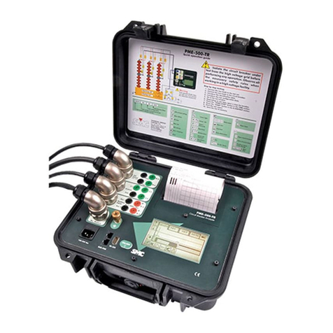
SMC Networks PME-500-TR User manual

SMC Networks

SMC Networks PME-500-TR User manual

SMC Networks IZH10 Series User manual

SMC Networks

SMC Networks IZH10 Series User manual

SMC Networks IN574-95 Instruction Manual

SMC Networks

SMC Networks IN574-95 Instruction Manual

SMC Networks IZH10 Series User manual

SMC Networks

SMC Networks IZH10 Series User manual

SMC Networks IZH10 Series User manual

SMC Networks

SMC Networks IZH10 Series User manual

SMC Networks IZH10 Series User manual

SMC Networks

SMC Networks IZH10 Series User manual

SMC Networks PFMV301 User manual

SMC Networks

SMC Networks PFMV301 User manual

SMC Networks PPA Series User manual

SMC Networks

SMC Networks PPA Series User manual

SMC Networks IZH10 Series User manual

SMC Networks

SMC Networks IZH10 Series User manual

SMC Networks PFG20 User manual

SMC Networks

SMC Networks PFG20 User manual

SMC Networks PFMV3 Series User manual

SMC Networks

SMC Networks PFMV3 Series User manual

SMC Networks ZSE10 Series User guide

SMC Networks

SMC Networks ZSE10 Series User guide

SMC Networks G46-L Series User manual

SMC Networks

SMC Networks G46-L Series User manual

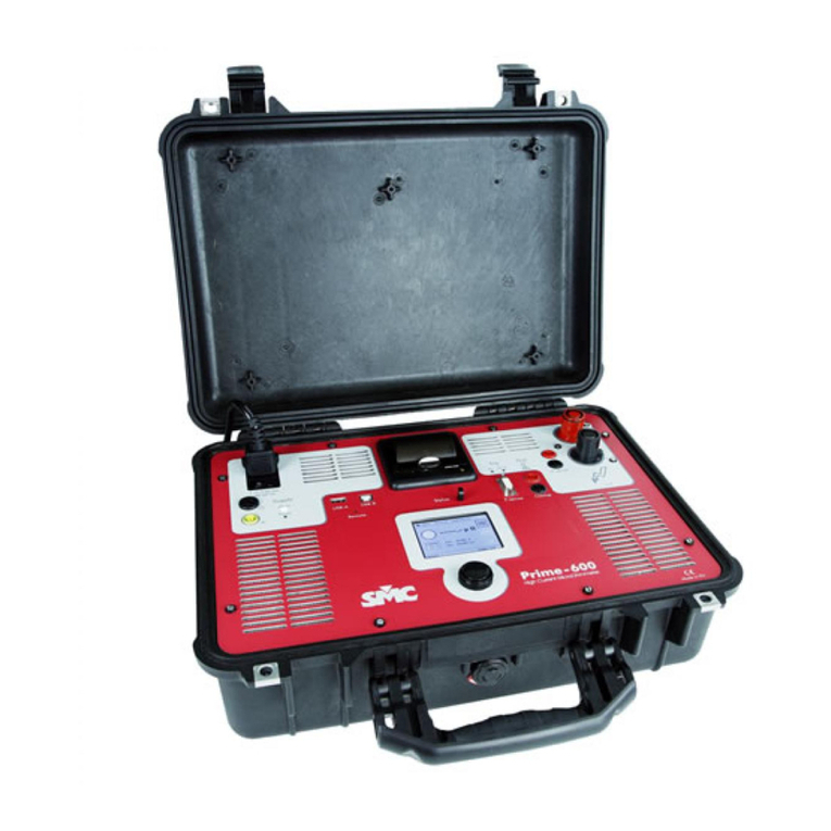
SMC Networks Prime-600 User manual

SMC Networks

SMC Networks Prime-600 User manual

SMC Networks PFMV3 Series User manual

SMC Networks

SMC Networks PFMV3 Series User manual

SMC Networks PSE201-A4C User manual

SMC Networks

SMC Networks PSE201-A4C User manual

Popular Measuring Instrument manuals by other brands

Hach POLYMETRON 8810 ORP Basic user manual

Hach

Hach POLYMETRON 8810 ORP Basic user manual

Heska Element DC5X Quick step guide

Heska

Heska Element DC5X Quick step guide

Leviton Verifeye 8000 Series Installation and user manual

Leviton

Leviton Verifeye 8000 Series Installation and user manual

KROHNE ALTOSONIC V installation manual

KROHNE

KROHNE ALTOSONIC V installation manual

GF DSR 100 instruction manual

GF

GF DSR 100 instruction manual

Megger DLRO10HD manual

Megger

Megger DLRO10HD manual

New Cosmos Electric SDM-73 instruction manual

New Cosmos Electric

New Cosmos Electric SDM-73 instruction manual

DAKOTA ULTRASONICS Z-304-0001 Operation manual

DAKOTA ULTRASONICS

DAKOTA ULTRASONICS Z-304-0001 Operation manual

WIKA IL-10 operating instructions

WIKA

WIKA IL-10 operating instructions

ddtop UFM Operation manual

ddtop

ddtop UFM Operation manual

ParTech 7300w2 Monitor instruction manual

ParTech

ParTech 7300w2 Monitor instruction manual

Emerson Rosemount Analytical CAT 100 instruction manual

Emerson

Emerson Rosemount Analytical CAT 100 instruction manual

Amprobe AC50A user manual

Amprobe

Amprobe AC50A user manual

Crompton Emotron VSR Series installation guide

Crompton

Crompton Emotron VSR Series installation guide

London Electronics INT2-P-DIFF manual

London Electronics

London Electronics INT2-P-DIFF manual

Meriam Instrument M2 Series user manual

Meriam Instrument

Meriam Instrument M2 Series user manual

Lumel N43 user manual

Lumel

Lumel N43 user manual

Hanna Instruments HI 8043 instruction manual

Hanna Instruments

Hanna Instruments HI 8043 instruction manual

manuals.online logo
manuals.online logoBrands
  • About & Mission
  • Contact us
  • Privacy Policy
  • Terms and Conditions

Copyright 2025 Manuals.Online. All Rights Reserved.