VistaVision 82026-630 User manual

InvertedMicroscope
Model
82026-630
OperatingManual

OperatingManualofInvertedMicroscope
-1-
Congratulations
ThankYouforyourpurchaseofaVWRVistaVisionMicroscope
Thisunitisaprecisionopticalinstrument.Ourproducthasbeendesigntoprovidethehighestlevelof
safety.However,improperoperationornegligence infollowing theinstructionsinthismanualmay
causepersonalinjuriesandpropertylosses.Inordertoensureyoursafety,tomaximize thelifeofthis
unitandtomaintainitproperly, pleasereadthrough thismanualcarefullybeforeoperatingthisunit.

OperatingManualofInvertedMicroscope
-2-
SafetyPrecautions &Reminder
1.Besuretoturnoff thepowerswitchandremovethepowercordplugbefore
installingthisunit,replacingthebulb/fuseorpluggingand unpluggingthe
powersupplyunit. Thisistopreventelectricshockorgettingfingersburnt.
2.Checkunitvoltageisincompliance withyourlocalpowersupplyvoltage,
otherwisecontactyoursupplier.Improperinputvoltagemay renderunitnot
workableorashortcircuitand damagetheunit.
3.Usespecifiedbulb, fuseand powercordwhichotherwisemay damagetheunit.
Anyextendedpowercordifused, mustbegrounded(PE).
4.Donotexposeunittohightemperaturesand dampness.Suitableoperating
environmentisbetween5 Cto35 C,andrelativehumidityof20%-80%(at
25 C). Donotsubjectunittodirectsunlight.
5.Donottouchthehalogenlampboxwhenusingtheunitasbulbsinside
generateexcessheatwhichcanburnyourhand.Donothandlebulbwithbare
hand within1
0minutesafterswitchingoff power
supplyasbulbisstillhot, especiallywhenchangingadefectivebulb.
6.Topreventfire,donotplace anyfibrousproduct,paper,flammableor
explosivematerial(e.g.,gasoline,petroleumether,alcohol)nearthehalogen
lampbox.
7.Whenusingcoarse/finefocusknobsorheightadjustmentknob,donot
continuetoturnthembeyond thelimitsortheinternalmechanismcanbe
damaged..
!
Warning!
!
Warning!
!
Warning!
!
Warning!
!
Warning!
!
Warning!
!
Warning!

OperatingManualofInvertedMicroscope
-3-
TableofContents
I. Characteristicsand applications ..................................................................................................-1 -
II. Structuralfeatures .............................................................................................................................-1 -
III. Installationofthisunit.....................................................................................................................-2 -
IV.Technicalspecifications ....................................................................................................................-4 -
V. Operation...............................................................................................................................................-5 -
VI. Replacementofbulband fuse......................................................................................................-13 -
VII. Maintenance.....................................................................................................................................-14 -
VIII.Troubleshooting.............................................................................................................................-15 -
OperatingManualofInvertedMicroscope
-1-
I. Characteristics andapplications
Theinvertedmicroscopeadoptsaninvertedstructurethatfocusesbylifting orloweringthe
objectives,andisprovidedwithlongworkingdistance planobjectivesandWide-fieldplaneyepieces.
Thelongworkingdistance condensersystemcanbeplacedintooroutofthelightpath,andissuitable
fortissueobservationinahighculturedish.Thephasecontrastdevice canbeattachedtothelightpath
toperformtransmittedphasecontrastmicroscopicobservation.Thisunitissuitableforthemicroscopic
observationofcells,tissuesandclearliquidtissues,andthedynamicmicroscopicobservationoftissues
culturedinaculturedish,andisapplicabletoscientificresearchinstitutions,collegesanduniversities,
medicalandhealth,inspectionandquarantineagencies,agricultural,animalhusbandryanddairy
industries.
II. Structuralfeatures
1 2 3 4
5
6
7
8
9
10
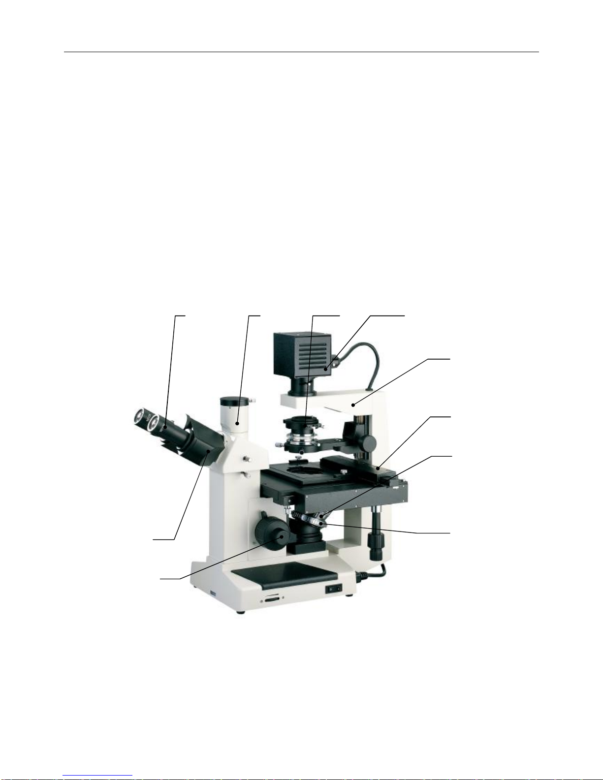
Fig.1
1. Eyepiece 2.Trinocularhead3. Phasecontrastcondenser4. Halogenlampbox5. Body
frame
6. Mechanicalstage7. Objective8. Nosepiece9. Coarse/finefocusing knob10. Eyepiece tube

OperatingManualofInvertedMicroscope
-2-
III.Installation
Caution
Beforeinstalling, besureeverycomponentsisclean, noscoreany
parts orglasssurface.
1
(2)
(2)
2
4
6
5
8
3
7
Fig. 2

OperatingManualofInvertedMicroscope
-3-
Thereare2styrofoamboxeswithinthecartonbox.
a) Thefirstboxcontains6objectives(3pcsplanobjectives10X,25X&40Xwithsingle
coloredringand3pcsplanphasecontrast10X,25X&40Xwithdoublecoloredringsand
marked PHP2”),1trinocular,2eyepieces,1centeringtelescope,3filters,1sparefuse
and1 sparelamp.
b) TheSecondboxcontains1bodyframe,1phasecontrastcondenser,3differentsize stage
bracketsholders.
Installationsteps
Thenumberinthefollowing installationstepsisshownintheinstalling diagram,suchas 1”is
Body”inFig.2
(1)Unpackthisunit,takeoutthebodyframe1 and place itonastableworkbench,andremovethe
supportingpackageandthedustcap(bag).
(2)Takeoutthephasecontrastcondenser4.Loosenthescrew onthecondenserholder3 and
theninstallthecondenserintotheholder,tightenthescrewagain.AsshowninFig. 3.
(3)Takeoutthestagebracket2 (whenthestagebracketisusedtocarryaspecimenorobservetissue
intheculturedish),putthedesiredspecificationstagebracketflatlyinthestagemoving device
rack ②.AsshowninFig. 3.
(4)Removethedustcapofeyepiece tube,inserttheeyepiece 5 intotheeyepiecetube,andturnthe
eyepiecessothatitfitstheeyepiece tubewell.
(5)Thereare6objectives.Thosewithsinglecoloredringareplanobjectivesandwithdouble
coloredringsarephasecontrastobjectiveswhicharealsomarked PHP2”.Installthemontothe
nosepiece.Usercanonlymount5objectivesontothenosepiece atanyonetime.Installthem
clockwiseintheascending orderofmagnificationAsshowninFig.4.
(6)Connectthepowercordtothepowersupplysocketofthebody.
(7)Checkiftheaboveinstallationissecureandsafe.
(8)Inspectandgathertheaccessoriesandtoolsenclosedinthepackageandkeeptheminasafe
place toavoidmisplacement.
Fig.3
①
②
Fig.4

OperatingManualofInvertedMicroscope
-4-
IV. Technicalspecifications
Totalmagnification
100X-400X(standard)
Mechanicaltube
length 160mm
Mainparameters
Conjugatedistance
ofobjective 195mm
WF10X fieldofview
number Ф20mm
Eyepiece Wide-fieldplan
eyepiece WF16X(optional)
fieldofview
number Ф11mm
Eyepiece
interface
Ф23.2mm
Parfocaldistance
10mm
TrinocularHingedbinoculartube,withanobservationangleof30°,and apupil distanceof53-75mm
Magnification Numerical
aperture Working distance
(mm)
Thickness of
cover glass
(mm) Remarks
10X 0.25 8.80 1.2
25X 0.40 4.78 1.2Objectives
40X 0.60 3.32 1.2
10X 0.25 8.80 1.2 Remark PHP2”
25X 0.40 4.78 1.2 Remark PHP2”
Phase-contrast
objective
40X 0.60 3.32 1.2 Remark PHP2”
Ultra-longworkingdistance condenserWorkingdistance 55mm, withphase-contrastdevice
longworkingdistancecondenser
(optional) Workingdistance 35mm, withphase-contrastdevice
Condenser
Longworkingdistance condenser
(optional) Workingdistance 70mm
Stage MechanicalStage,movingrange79mm(longitudinal)X130mm (transverse), detachablestage
movingdevice
Holder1 86mm (W)X129.5mm (L),optionalwithacircularculturedish Ф87.5mm
Holder2 34mm (W)X77.5mm (L), optionalwithacircularculturedish Ф68.5mm
Stagebracket
Holder3 57mm (W)X82mm(L)
Lightsource Transmitted
lighting6V/30Whalogenlamp, adjustableinbrightness

OperatingManualofInvertedMicroscope
-5-
V. Operation
●InvertedMicroscopeOperation.
1.Turningonthepowerswitchand brightness adjustment
Turnonthetoggleswitch ontherightofthebodyframe,sothatthetransmittedhalogenbulb
isilluminated.Turnthebrightness controlknob toadjustthebrightnessofthebulb,andmake
thebrightness ofthefieldofviewsuitableforvisualinspection.AsshowninFig. 5.
2.Adjustmentofthecondenserheight
Beforethisunitisreleasedfromthefactory,thecondenseralreadybearsacalibratedheightmark
①,Turnthecondenserheightcontrolknob ,tomovethecondenserintoworkingpositionuntil
thetwolinesonthecondensercoincidewhichisoptimumpositionformostapplications. asshown
inFig. 6.
②
Fig. 6
①
Caution
!
Donotkeepthebrightnesscontrol
knobatthebrightestpositionfora
prolongedperiodoftime,otherwisethelifeofthebulbmaybeshortened!
Whenthisunit isnotinuse,turnthebrightness adjustingknobtothelow
positiontomaintaintheelectricfunctionsofthisunit.
①
②
Fig. 5

OperatingManualofInvertedMicroscope
-6-
3.Adjustmentofphase-contrastdevice
Setthephasecontrastpuller ①tothecentrallighthole, asshowninFig.7.
4. Resetofdiopteradjustmentring
Turnthediopteradjustment ring ①onthelefteyepiecetube,sothatthe 0”diopter positionis
alignedwiththesidescale(remarkwhiteline), asshowninFig.8.
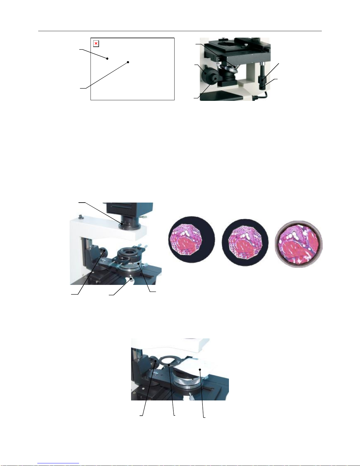
5.Adjustmentofinterpupillarydistance
Parallaxcanbeeliminatedbyadjustingtheinterpupillarydistance sothatthedistance ofthe
eyepiece tubeisidenticalwithyourinterpupillarydistance andenableyoutoobservemore
comfortablyandclearly.Whenyouobservethroughtwoeyepieces,ifthefieldofviewconsistsof
twooverlapping circles,asshownFig.8-a,youcanaltertheexitpupil centerdistance ofthe
eyepiece tubesbyturningtheleftorrightframebody untilthefieldofviewbecomesafully
overlappedcircle, asshowninFig. 8-b.
6. Inspectionoftransmittedlightingpath
Theopticalsystemofthisunithasbeencalibratedbeforefactoryrelease.Butthecenterofthe
lightingbulborcondensersystemmaydeviatefromthecenteroftheopticalsystemduetoany
possibleviolentvibrationorinclinationduring transport.Aftertheaboveinstallationand
adjustment,thelightpathoftheopticalsystemshouldbechecked.
(1)Inspectionofcenteroffielddiaphragm
A.Putthetestslide .asanexampleintheselectedStagebracket ②.Turnthe10Xplan
objective ③intothelightpath.Turnthestagemovingdevice controlknoband ④and ⑤
tomovethesliderightabovethe10Xobjective.Adjustthefocusbythecoarseandfinefocus
knobs ⑥and ⑦tomaketheimageofslideinthefieldofviewclear.AsshownFig.9.
①
Fig. 7
①
②
Fig. 8
a b
OperatingManualofInvertedMicroscope
-7-
B.opentheaperturediaphragm ④,andclosethesmall fielddiaphragm ①,whenalightspotas
showninFig.11-acanbeseeninthefieldofview.Iftheedgeofthelightspotisunclear,it
canbemadeclearbyadjustingthecondenserheightcontrolknob ②.
C.Ifthelightspotdeviatesfromthecenterofthefieldofview,asshowninFig.10-a,the
condensercenter(centerofaperturediaphragm)mustbeadjusted. Thecenterofthelightspot
cancoincidewiththatofthefieldofviewbyadjustingtwothecenteringscrews ③ofthe
condenserholder, asshowninFig. 10-b.
D.Openthefielddiaphragm,sothattheobservedspecimenimagefillsthevisualfield,asshown
inFig.10-c.
(2)Inspectionofalignmentofilluminator
A. Prepareapiece ofwhitepaper(about40mmX50mm) ③, unscrewthefilterholder onthe
phasecontrastcondenser, andplace thewhitepaperonthetopofthephasecontrast
condenser, asshowninFig. 11.
①
②
③
④
⑤
⑦
⑥
Fig.9
①
Fig.10
②
③
a
b
c
④
②
Fig.11
③
①

OperatingManualofInvertedMicroscope
-8-
B.Atthispoint, abrightlightspotwillbeshownonthewhitepaper, withafilamentimage
inside. Ifthefilamentimageisunclear, itcanbemadeclearbyadjustingthecollectorlens
adjustinghandle ④.
C.Ifthefilamentimagedeviatesfromthecenterofthebrightlightspot,asshowninFig.12-a,
thebulbmustbecentered.Todothis,loosenthescrews ⑦,andmovethelampholder ⑥
gentlyadjusttheleft-rightcenteringofthebulb, as indicatedbythearrowinthefigure.
D.IfitisnecessarytocenterthebulbfrontandrearasindicatedbythearrowintheFig.12,the
wholelampholder ⑩andthebulb ⑨,mustberemovedasshowninFig.13.Thiscannotbe
doneuntil thebulbiscool.Wrapthebulbwithacottonfabric ⑧,andadjustthebulb
verticallygently(inthedirectionindicatedbythearrowinFig.13).Thiscancenterthebulb
frontandrear.
7. Placementofspecimenslice orculturedish
(1)Toobserveaslidespecimen ,theslidecanbeplaceddirectlyonthestagebracket ②.To
observetissuesinaculturedish,determinethestagebrackettobeusedbasedontheexternal
dimensionsoftheculturedish(refertothetechnicalspecificationtablefortheallowableculture
dishdimensions), asshowninFig.14.
⑧
⑨
⑩
Fig. 13
Caution
!
Donotadjustthebulbtoohard,asthis
will addtothedifficultyofprecise
adjustment.Thebulbshouldnotbe
removedforadjustment
until it iscool.Do
notpull thebulbtoohard,otherwisethe
feetmayburst.
⑥
⑤
⑦
④
Fig.12
a b c
②
Fig. 14
①

OperatingManualofInvertedMicroscope
-9-
(2) Adjustthestagemovingdevice controlknob ①and sothattheobservedarea isrightabove
theobjectiveforeasyobservationandadjustment,asshowninFig. 15.
8. Coarseand finefocusingcontrolknoboperation
(1)Focuswiththe10Xobjective
Turnthenosepiece ①tomovethe10Xobjectiveintothelightpath(whenitturnsinplace,the
objectivewill snapautomatically), asshowninFig. 16.
(2)Turnthecoarsefocusing controlknob ③tolifttheobjectivetothehighestpoint.Thenobserve
throughtheeyepiece.Turnthecoarsefocusingcontrolknobslowlytolowertheobjective.When
aspecimenimageappearsinthefieldofview, stopturningthecoarsefocusingcontrolknob, as
showninFig. 16.
(3)Turnthefinefocusingcontrolknob ②forfinefocusing tomakethespecimenimageclear,as
showninFig.16.
(4)Locktheobjectiveliftinglimithandwheel ④asindicatedbythearrowinthefigure, asshownin
Fig. 16.
Whenyou’regoingtouseahigh-powerobjective, firstusethe10Xobjective
tofocusandsetthelimithandwheel.Whenmountingahigh-power
objective,raisetheobjectivetothelimit heightwithacoarsefocusing
control
knob directly, andthenfocusfinelywiththefinefocusing controlknob.
Reminder
!
①
②
Fig.15
Fig.16
①
②
③
④

OperatingManualofInvertedMicroscope
-10 -
9.Adjustment, assemblyand removalofstagemovingdevice
(1)Thelongitudinal(Y)andtransverse(X)movementofthestagemoving device ①isrealizedby
thelongitudinaladjustingknob andthetransverseadjustingknob ③thatarecoaxial,as
showninFig. 17.
(2)Ifobserving tissuesinabigculturedish,thestagemoving scale ①onthefixedstagemustbe
removed.Duringremoval,keepthecondensersystem ④outofthelightpath,removethestage
bracket,andlowertheobjective(turnthecoarsefocusing controlknobsothattheobjective
lifting mechanismislowered).Useascrewdrivertoloosenthe3mountingscrews ⑤atthe
bottomofthestagemovingdevice,removethestagemoving device ⑥,andlayitflatlyonthe
worktableupsidedown. Donotlayitlaterallyoroverhead, otherwiseitmaydroporbedeformed,
affectingtheprecisionofthisdevice. See Fig. 18 fortheoperatingprocess.
Caution
!
Thestagemoving deviceisdrivenbygearandrack. Incaseoflongitudinalor
transversemovementtothefixedposition(maximum),donotcontinuetoturn
theadjustingknob
asthisislikelytodamagethemovementadjusting
mechanism.Whenthestagemovingdevice protrudesfromthefixed
stage,the
rackwillextendoutward.Becarefulnottolettherackhit yourhandorany
otherpartofyourbody.
Y
X
①
②
③
Fig. 17
Fig.18
④
⑤⑥

OperatingManualofInvertedMicroscope
-11-
(3) Diopteradjustment
Dioptercanbeadjustedbythediopteradjustingring ①onthelefteyepiece tube,whichcan
correctanydiopterdifference betweenbotheyesofdifferentusers.
A.Turnthe40Xobjectiveintothelightpath,andobservethespecimenimageintheright
eyepiece (theeyepiece intheeyepiece tubewithoutthediopteradjustingring)withtheright
eyealone, andfocusuntil aclearimageisseen.
B.Observethespecimenimageinthelefteyepiecewiththelefteye.Iftheimageisunclear,itis
necessarytoadjustthediopteradjustingring ①sothatthelefteyecanalsosee aclearimage.
ThediopteradjustingrangeofthisunitisN=±5diopters, asshowninFig.19.
●PhaseContrastMicroscopicObservation
1.Adjustmentofphasecontrastdevice
Turnthe10Xphasecontrastobjectiveintothelightpath,andturnthephasecontrastturntable
orphasecontrastpullertothe 10”scale.Turncondenserheightcontrolknob,sothatthephase
contrastcondenserrisestothepositionofscale.
2. Positioningofspecimen
Laythephasecontrastspecimenflatlyonthestagebracket(see Fig.14)ordirectlyonthefixed
stage(removestagemoving device). Focustomakethespecimenimageclear.
Fig. 19
①
Caution
!
Thestagemoving device isthekeypartforcarryingthespecimenandtheculture
dish. Donotlayit laterallyoroverheadafterremoval,otherwiseit islikelytodrop,
affectingitsprecision.Itshouldbelaidflatlyontheworktableupsidedown.
Inthephasecontrastobservationmode,thephase
contrastobjectivemust
correspondtothephasecontrastring plateinthephasecontrastcondenser
,
i.e., themagnificationoftheobjectivecorrespondstothescaleofthepulleror
insertplate, otherwisetheimagingeffectofphasecontrastobservati
onwould
beaffected.
Reminder
!

OperatingManualofInvertedMicroscope
-12 -
a
①
③
④
⑤
b
c
d
Fig.20
②
3. Centeringofphasecontrastdevice
(1)Removeoneeyepiece fromtheeyepiece tube,andinsertthecenteringeyepiece intothe
eyepiece tube, asshowninFig. 20-a.
(2)Adarkring ④andabrightring ⑤canbeobservedinthefieldofviewofthecentering
eyepiece, asshowninFig. 20-c.
(3)Iftheedgeofthedarkringsandbrightringsisunclearinthefieldofview,theadjustingring ①
ofthecenteringeyepiece canbeadjustedtomaketheedgeclear.
(4)Inthephasecontrastobservationmode,thecenterofthedarkringshouldcoincidewiththatof
thebrightring. Iftheircentersdonotcoincide, asshowninFig. 20-c,itisnecessarytocenterthe
phasecontrast. Thiscanbedonebyadjustingthecenteringscrews ③ofthepullerphasecontrast.
TheadjustedthefieldofviewisasshowninFig. 20-d.
(5)Afterthephasecontrastdevice iscentered,thecenteringeyepiece canberemoved,andthe
workingeyepiece insertedagain.
Caution
!
Incaseofchangeovertoaphase-contrastobjectiveofadifferentmagnification, the
phase-contrastdevicemustbecenteredagain, otherwisetheeffectofobservation
phase-contrastwouldbeaffected.

OperatingManualofInvertedMicroscope
-13 -
●OperationofTrinocularDevice
Thisunitperformsvisualinspectionandphotographicobservationthroughpush-pull changeover.
1Loosenthefastening screws ofthephotographicoutputtube,andremovethedustcap ①of
thephotographicoutputtubeasshownonFig21
2Mountthephotographicdevice ontheoutputtube, andthentightenthefastening screws.
3Pulloutthephotographic/visualchangeoverpusher ③, theimagewillshowinthemonitoror
displayscreen
VI. Replacement ofbulband fuse
●HalogenLampReplacement
1.Turnoff thepowerswitch , andunplug thepowercord ②, asshowninFig. 23-a, 23-b.
2.Waitatleast10 minutesuntil thebulbanditssurroundingshavecooldown. Thisistoprevent
handgettingburntbyheat.
3.Unscrewthescrew ⑤,loosenthescrew ④,and pull outthelampholderfromthehalogenlamp
housing.Useaclothtoremovethedefectivebulbasitmaystill beveryhotafteruse.Replace
thehalogenbulbandplace backthelampholderintoposition.Thebulbfeetshouldbeinserted
asdeeplyaspossible,otherwisethelifeofthebulbmaybeshortenedduetobadcontactorthe
bulbmaynotbeilluminated.AsshowninFig. 23-d.
4.Checkandadjustthecenterofthebulbaccording totheabove-mentionedcenteringmethodfor
thealignmentofilluminatorintheinvertedmicroscopeoperation.
Toreplacethebulbandthefuse,
turnoffthepowerswitchandunplugthe
powercord,otherwisefire,personalinjuryordamagetothisunitmay
occurduetoelectricshortcircuit.
!
Warning!
②
③
①
Fig.21
a ①
Fig. 23
②
b
c
d
③
⑤
④
OperatingManualofInvertedMicroscope
-14 -
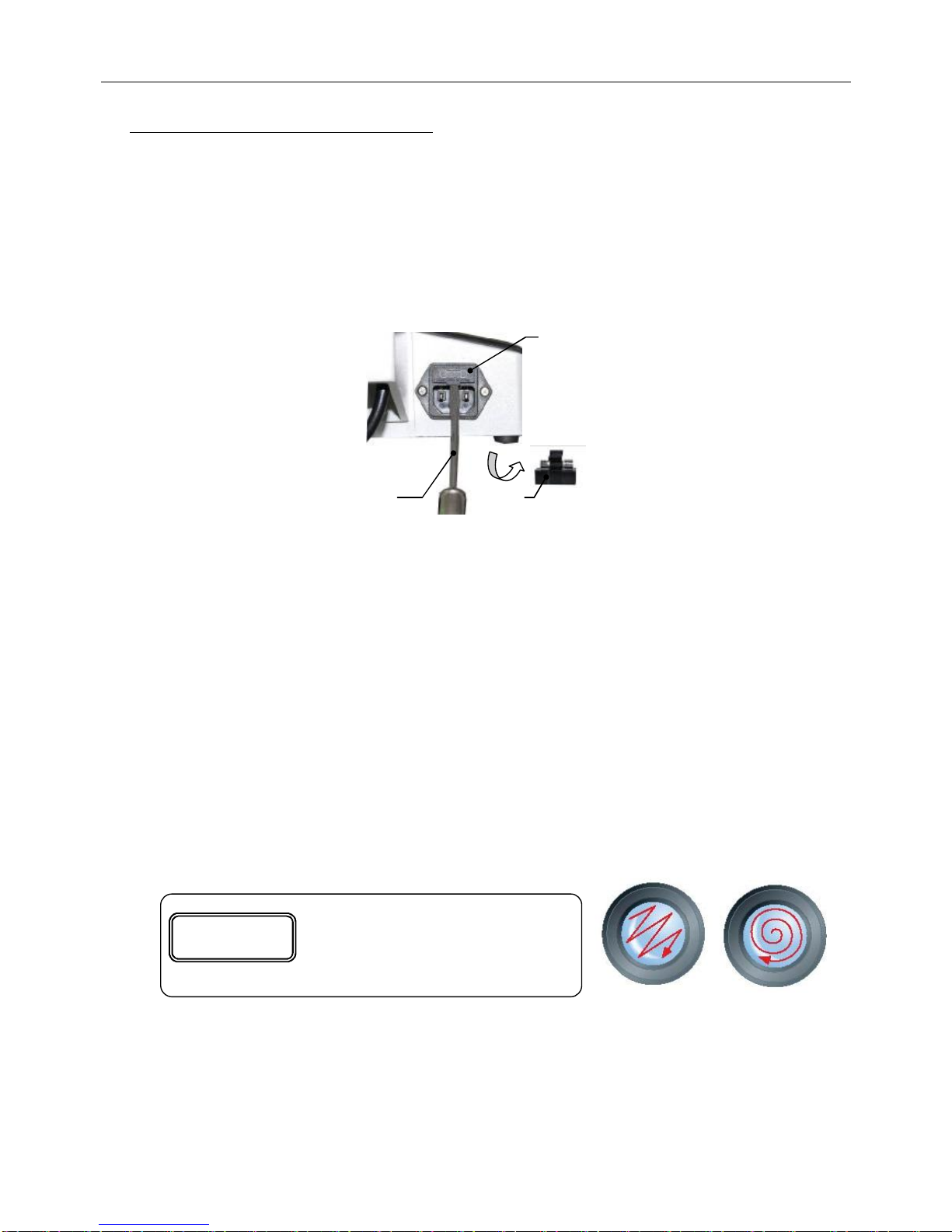
●ReplacementOfTheMainUnitFuse
Thefuseofthemainunitisacircuitsystemusedforhalogenlamp, andisintegratedintothepower
inputsocket ③ofthemainunit.
1.Turnoff thepowerswitch ①, andunplug thepowercord , asshowninFig. 24.
2.Removethefuseholderwithaflatscrewdriver ①oranyothertoolasshowninthefigure,
removethedamagedfuse,andreplace anewone.Replace thefuseholderintothepowerinput
socketofthemainunit, asshowninFig. 24.
3. Reconnectthepowercord,andcheckifthefusetubeisingoodcontact.
VII. Maintenance
1. Thepowerswitchofthemainunitisthepowercontrol.Whenfinishusing thisunit,press the
switchto “O”tocutoff thepowersupply,unless theelectriccomponentsinthisunitisstill
operating.Whenthisunitisnottobeusedforalongtime,removethepowerplug fromthe
supplysocketandkeepallcablesproperly.
2. Thisunitshouldbekeptclean.Removeanyoilonthelensandcleanthebodywithcleangauze
(orsilkfabricorabsorbentcotton)dippedwithalittlealcohol.Putonthedustshielduntil this
unitiscompletelycoolanddry.
3.Cleaningthelens
Blowoff orwipeoff anydustonthelenswithablowerballorasoftbrush;heavydirtand
fingerprintscanberemovedwithlenstissueorsoftclothdippedwithalittlemixtureofalcohol
andethylethergently(themixratiois:alcohol20-30%andethylether70-80%).
4. Cleaning thesurface ofthisunit:Wipeitwithcleansoftcloth;heavydirtmaybewipedoff witha
neutraldetergent.
Fig. 24
①
②
③
Wrong
Right
Itiseasiertocleanthelensbywiping
themfrominsideoutasshowninthe
figure.
Reminder
!

OperatingManualofInvertedMicroscope
-15 -
5. Keeping:Whenthisunitisnottobeusedforalongtime,turnoff thepowersupplyofthisunit,
allowthebulbtocooldownsufficiently,putonthedustshield,storethisunitatadry,ventilated
andcleanplace free fromanyacid, alkali orsteam,otherwisemoldmaydeveloponthelens.
6. Periodicinspection:Thisunitshouldbeinspectedandmaintainedperiodicallytomaintainits
performance.
VIII.Troubleshooting
Fault Cause Solution
Electricsystem
Thepowerswitchisnotturnedon. Turnonthepowerswitch.
Thehalogenlampisdamaged. Replace thehalogenlamp.
Thefuseisdamaged. Replace thefuse.
Theconnectoroftheelectricchassisis
inbadcontact. Checkandhaveaprofessionalrepairit.
Nolightshowninthefieldof
viewusinghalogenlamp
Thehalogenlampmountedis
nonconforming. Useaconforming halogenlamp.
Opticalsystemandimaging
Thenosepiece hasnotbeenturnedto
thefixedposition. Turnthenosepiece tothefixedposition.
Thefilamentimagedeviatesfromthe
centerofthecollector. Repositionthelightingbulb.
Thereisdirtoroil onthesurfaceofthe
objective,eyepiece orcondenser Wipethelenssurface orreplacethelens.
Thereisablackshadowon the
edgeofthefieldofviewor
unevenlyilluminated,makingit
impossibletoobservethewhole
fieldofview.
Thefieldofviewdiaphragmisnot
opencompletely. . Openthefieldofviewdiaphragm.
Oil ordustisfoundinthefieldof
view. Thereisoil ordustontheeyepiece
lens. Wipetheeyepiece.
Caution
!
Donotwipethisunit withanyorganicsolvent(e.g., alcohol, ethyletherorits
dilutesolution), otherwisethesurfacepaintofthisunitmaycomeoff. Itis
suggestedthatalayerofnon-corrosivelubricantisappliedonthemoving
partsofthisunitbeforethedustshieldisputon, and place theeyepiece and
theobjectivesinacontainerwithdesiccant.

OperatingManualofInvertedMicroscope
-16 -
Thereisoil oranyforeignobjecton
theedgeofthefieldofview
diaphragm. Wipethediaphragmedge.
Theobjectiveisdamaged. Repairtheobjective(byaprofessional).
Thereisoil ordustonthesurfaceof
thelensoftheobjectiveoreyepiece. Wipetheobjectiveortheeyepiece.
Theapertureoftheaperturediaphragm
istoosmall.
Adjusttheapertureoftheaperture
diaphragmbasedontheobjective
magnification(ornumericalaperture)
used.
Theobjectivedeviatesfromthelight
path. Turnthenosepiece tothefixedposition.
Thespecimencoverglass istoothick
orthin. Loadacoverglass asnecessaryforthe
objective.
Theupperandlowersidesofthe
specimenareinverted. Place theupperandlowersidesofthe
specimenpositively.
Offsetfocalplan
orlow
resolution
Theoil hasnotbeewipedoff timely
and remainsforaprolongedperiodof
time. Wipethefrontlensoftheobjective.
Thelightingbulb isseriouslyinclined.
Repositionthelightingbulb.
Thefocalplaneoftheimageis
inclined(brighterononesideand
darkeron theother) Thespecimenisnotlaidflatly. Laythespecimenflatlyon the
objectstage
and holdit stably.
Thephase-contrastobjectivedoesnot
matchtheringplateofthe
phase-contrastcondenserlens.
Alignthephase-contrastobjectivewith
themarkontheturntableofthe
phase-contrastcondenserlens.
Thecenteroftheringplateofthe
phasecontrastcondenserlensdeviates
fromthatofthephaseplateofthe
phasecontrastobjective.
Centerthephase-contrastcondenserlens,
sothattheringplatecoincideswiththe
phaseplate.
Theeffectofphase-contrast
observationisbad.
Thespecimenusedisnotsuitablefor
phase-contrastobservation. Replace it withonesuitablefor
phase-contrastobservation.
Mechanicalsystem
Thefocusingmechanismflows(slides
down)automatically. Adjustthecoarseadjustinghandwheel.
Thefinefocusingmechanismfails Checkandhaveaprofessionalrepairit.
Theimagecannotremainclear
duringobservation.
Thestageloosensorisinclined. Checkandhaveaprofessionalrepairit.
Thelockscrewsloosen,making
positioningdifficult. Recalibratethelockscrews.
Whenthecondenserlifting
device swingsinorout, thefixed
positioncannotbelocated
preciselyorisinsecure. Thelockingmechanismisseriously
worn, andhasinsufficientclamping
force. Checkandhaveaprofessionalrepairit.
Table of contents


