Vistron COBRANET DIGITAL SNAKE CABLE User manual

User’s Manual
COBRANET DIGITAL MULTI/SNAKE CABLE
Model No. : CN24R/T
Model No. : CN40R/T

•CAUTION •
Attention / It may be caused the
breakdown of product and an injury.
Please avoid drop and shock of product
and also do not put the heavy thing
above the product.
It can be a cause of Breakdown and
damages.
Please take care to prevent the dust and
dirty things into the products.
It can be a cause of Breakdown and
damages.
Please do not sprinkle the water in the
product and do not wipe with Benzene,
Thinner or Chemical Substance etc…
It will be able to be caused Fire, Electric
Shock and deterioration on the surface of
product.
If there is some strange smell or smoke
from the product, please take out the
power plug and call to Service Center.
If you use continuously, it would be able to
fire or doing injury.
Please keep the products and accessories
in safe place which the children cannot
touch.
Danger / It may can be caused the electric
shock and injury.
Please do not Disjointing, Repair and
reorganization absolutely.
It will be able to Fire and electric shock.
In case of using the products in moisture area
such as beach, swimming pool or rainy day,
please take care to prevent the Sand and
Water into the products.
It can be a cause of Breakdown and
damages.
Please avoid the moisturized place or high
difference temperature place when use our
products.
If you use continuously, it would be able to
breakdown and electric shock.

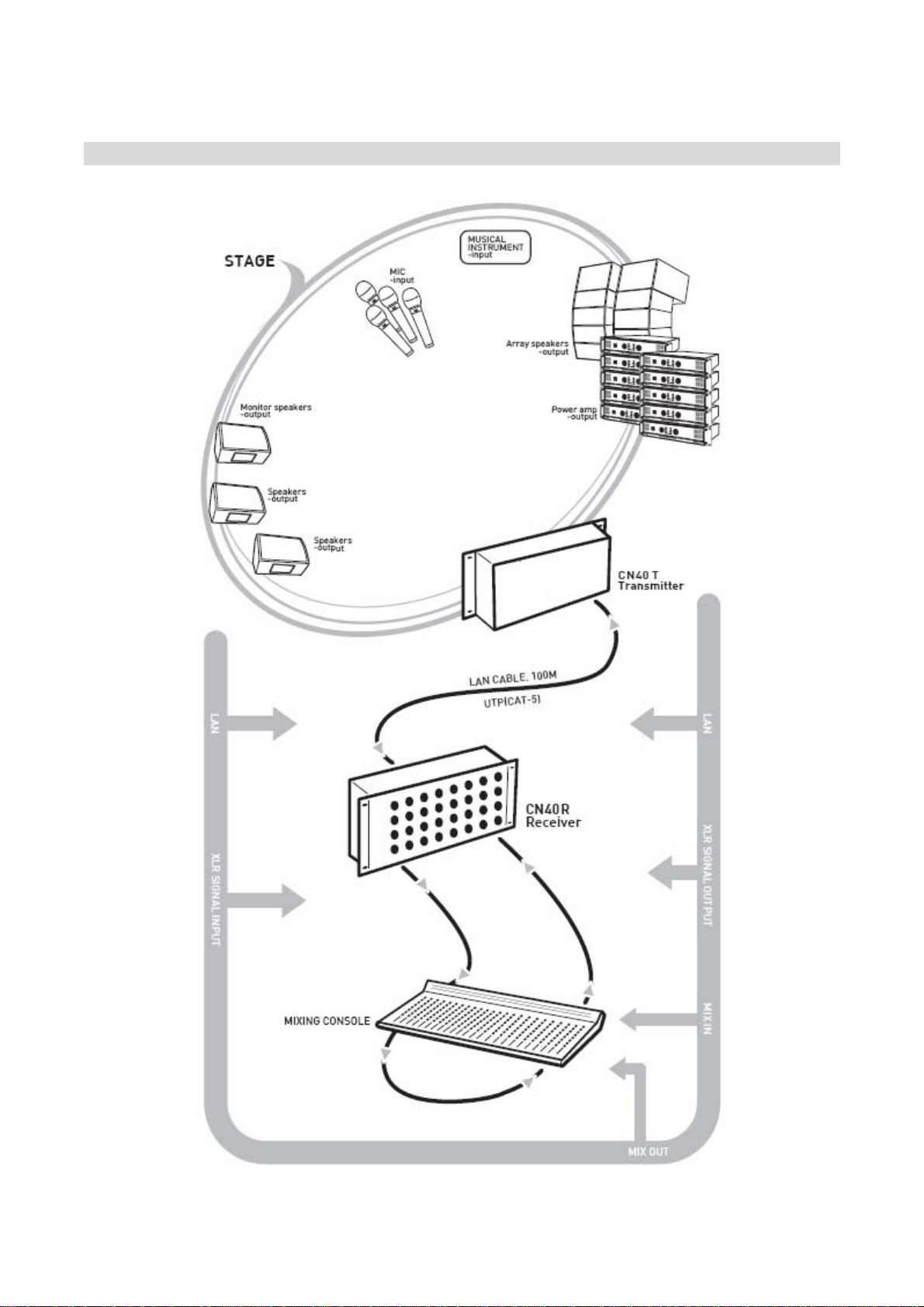
•PRODUCT OVERVIEW •
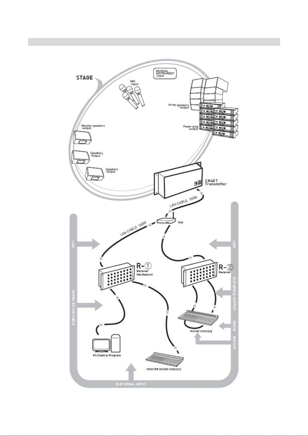
Our CN24RT &CN4RT are built in high-quality A/D and D/A converters and those converts
the Analog input-output Signal to Digital Signal and transmit the signal using UTP (CAT-5). It
contains Transmitter Box which converts the Analog Signal to Digital and Receiver Box
which convert the Digital Signal to Analog Signal.
It is available to transmit and receive the Digital Audio Signal of 40 Channel (24Channel)
simultaneously through Ethernet Network adopted CobraNet.
Also it can transmit the digital signal through UTP(CAT-5) Cable until 100 Meter in stable. In
case of over 100 Meter, you can extend the length of UTP cable easily using Ethernet Hub.
If you use our CN40RT and CN24RT in large sized sound system, you can save the cost of
analog cable and wiring. And it’s quite effective to reduce the cost in where is installed
CobraNet Network Infra.
And also, it will be helpful to solve the problems of Noise, Attenuation of Signal which come
out from Analog Cable.
Stable Function with high quality sound, No more worry about Noise
It’s solved the problem of signal diminution and noise influx problem in long distance signal
transmission and realized the clean sound environment.
Construction with only one strand of LAN using Ethernet Protocol
It’s available to transmit the signal in stable with CobraNet Program and also can be
transmitted and received Audio Signal (32Ch & 16Ch) using only one strand of UTP Cable
(CAT-5).
Built-in Hub inside and Connect easily between equipments
It’s available to connect the various equipments easily without extra Hub since our product
is built-in Hub inside and put out the link terminal on the outside.
Easy Extension using Ethernet Hub
Normally the length of CAT-5 is 100Meter, but it can be easily extended the length over
100Meter using Hub.
Economic Price
Suppose to transmit the 40Ch of signal using Analog Cables, it’s necessary lots of analog
cable and it’s not easy wiring.
Our CN40 (CN24) solve this problem completely.
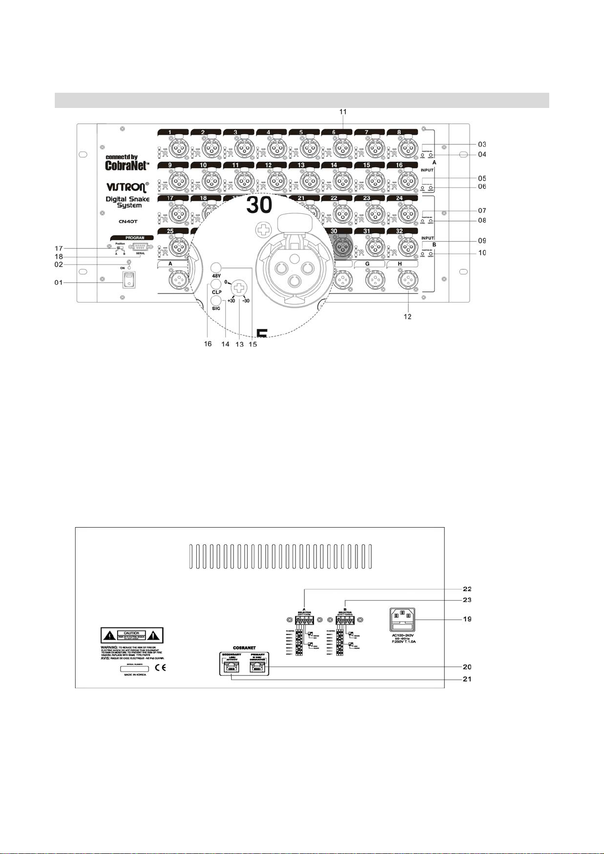
•NAME OF EACH PART OF CN40T •
01 Power Switch 02 Power LED
03 1-8CH Phantom Select Switch 04 1-8CH Phantom On/Off Switch
05 9-16CH Phantom Select Switch 06 9-16CH Phantom On/Off Switch
07 17-24CH Phantom Select Switch 08 17-24CH Phantom On/Off Switch
09 25-32CH Phantom Select Switch 10 25-32CH Phantom On/Off Switch
11 Analog IN XLR Jack 12 Analog OUT XLR Jack
13 AnalogGainControl 14 LEDSignalLamp
15 Phantom Power LED 16 Clipping Level LED
17 Serial Group Select Switch 18 Serial Connector
19 ACin 20 CobraNetConnector
21 LINKConnector 22 AOptionControlDipSwitch(CH1-CH16)
23 B Option Control Dip Switch(CH7-CH32)

•EXPLAINATION FOR EACH PART OF CN40T •
01 Power Switch
Power Switch for Power on/off.
02 Power LED
On power switch, LED Lamp is turned on
lighting.
03,05,07,09 Phantom Select Switch(9-32CH)
These are channel select switch for
turn-on/turn-off of Phantom +48V.
If you select the channel, the Signal LED
Lamp is twinkle.
04,06,08,10 Phantom On/Off Switch(9-32CH)
After select the Channel with Channel
Select Switch, if you put once, Phantom
Power is ON. And if you put one more,
Phantom Power is Off.
11 Analog IN XLR Jack
1 =>GND, 2 =>HOT, 3 =>COLD Analog Input
12 Analog OUT XLR Jack
1 =>GND, 2 =>HOT, 3 =>COLD Analog Output
13 Analog Gain Control
If you turn the control to counterclockwise,
the signal is diminished. And if you turn to
clockwise, the signal is amplified. The input
scope is +30dB ~ -30dB.
14 LED Signal Lamp
LED Indicates input signal. In case input of
Phantom Select Switch, indicate the channel
selected.
15 Phantom Power LED
LED Indicates the status of Phantom power.
16 Clipping Level LED
LED indicates excess analog input.
17 Serial Group Select Switch
It is available to connect equipment with PC
through RS-232 Cable. To control equipment,
please use Default Setting Program as below;
- In case Receiver(1-16Rx), the Group Select
Switch should be selected to A 1-16.
- In case Receiver(17-32Rx), the Group
Select Switch should be selected to B 17-32.
And push the SET (OK) botton for Setting.
18 Serial Connector
It is Serial Connector to connect with PC using
Serial Cable which should be connected
No.2,3,5 each. The control program is in CD
enclosed.
19 AC IN
This is AC Power Input Terminal
20 CobraNet Connector
It’s the connecto to connect the equipments
by LAN Cable.
21 LINK Connector
This is connector for LINK Connection between
equipments.
22, 23 Option Control Dip Switch
No.1-3 Switch is the transmitting and receiving
Group Select Switch.
No. 4 Switch is for the selection of Transmitting
or Receiving.
No. 5 Switch is Return Selection Switch in
Receiving Mode.
The detailed information, please refer the
next page.

<Detailed Information of Option Control Dip Switch>
No.1-3 Select Switch is for Group Selection and the connection should be selected in same
Group in case of connection between the equipments of Conet1616.
1-Off, 2-Off, 3-Off PC Control (It’s used to control Phantom, No. of Channel or Group using
PC)
1-On, 2-Off, 3-Off Group Number 1
1-Off, 2-On, 3-Off Group Number 2
1-On, 2-On, 3-Off Group Number 3
1-Off, 2-Off, 3-On Group Number 4
1-On, 2-Off, 3-On Group Number 5
1-Off, 2-On, 3-On Group Number 6
1-On, 2-On, 3-On Group Number 7
No. 4 Switch is for the selection of Transmitting or Receiving
(4-On : Transmitting Equipment, 4-Off : Receiving Equipment)
No. 5 Switch is Return Selection Switch to Transmitting Equipment in Receiving Mode.
(5-On : Available Return Function, 5-Off : Not available Return).
Remark : In case of CN40RT, Group Select Switch of No.1-3 should be same with each
Select A Switch and Select B Switch of CN40T & CN40R. But, Select A & B should
be different.
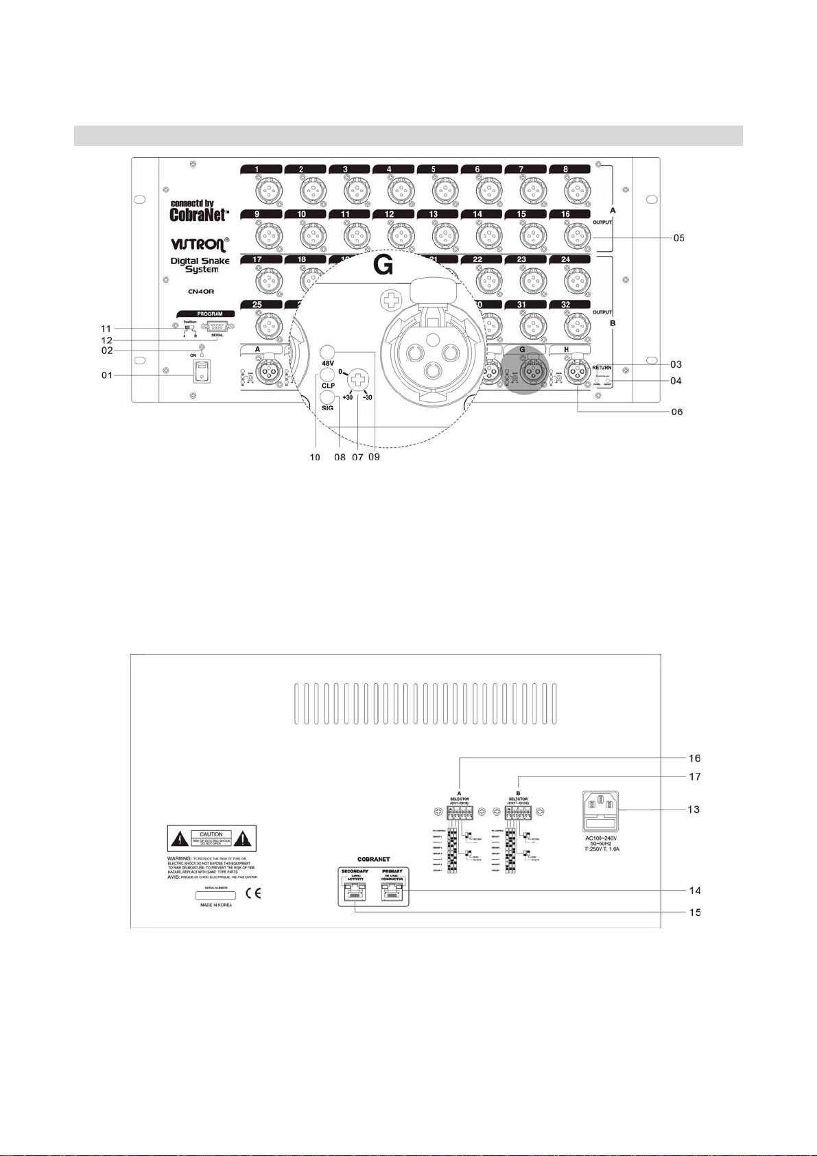
•NAME OF EACH PART OF CN40R •
01 PowerSwitch 02 PowerLED
03 Return A-HCH Phantom Select Switch
04 Return A-HCH 1-8CH Phantom On/Off Switch
05 AnalogOUTXLRJack 06 AnalogINXLRJack
07 AnalogGainControl 08 LEDSignalLamp
09 PhantomPowerLED 10 ClippingLevelLED
11 SerialGroupSelectSwitch 12 SerialConnector
13 ACin 14 CobraNetConnector
15 LINKConnector 16 AOptionControlDipSwitch(CH1-CH16)
17 B Option Control Dip Switch(CH7-CH32)

•EXPLAINATION FOR EACH PART OF CN40R •
01 Power Switch
Power Switch for Power on/off.
02 Power LED
On power switch, LED Lamp is turned on
lighting.
03 A-HCH Phantom Select Switch
These are channel select switch for turn-on/
turn-off of Phantom +48V. If you select the
channel, the Signal LED Lamp is twinkle.
04 A-HCH Phantom On/Off Switch
After select the Channel with Channel Select
Switch, if you put once, Phantom Power is ON.
And if you put one more, Phantom Power is
Off.
05 Analog IN XLR Jack
1 =>GND, 2 =>HOT, 3 =>COLD Analog Input
06 Analog OUT XLR Jack
1 =>GND, 2 =>HOT, 3 =>COLD Analog Output
07 Analog Gain Control
If you turn the control to counterclockwise,
the signal is diminished. And if you turn to
clockwise, the signal is amplified. The input
scope is +30dB ~ -30dB.
08 LED Signal Lamp
LED Indicates input signal. In case input of
Phantom Select Switch, indicate the channel
selected.
09 Phantom Power LED
LED Indicates the status of Phantom power.
10 Clipping Level LED
LED indicates excess analog input.
11 Serial Group Select Switch
It is available to connect equipment with PC
through RS-232 Cable. To control equipment,
please use Default Setting Program as below;
- In case Receiver(1-16Rx), the Group Select
Switch should be selected to A 1-16.
- In case Receiver(17-32Rx), the Group
Select Switch should be selected to B 17-32.
And push the SET (OK) botton for Setting.
12 Serial Connector
It is Serial Connector to connect with PC using
Serial Cable which should be connected
No.2,3,5 each. The control program is in CD
enclosed.
13 AC IN
This is AC Power Input Terminal
14 CobraNet Connector
It’s the connecto to connect the equipments
by LAN Cable.
15 LINK Connector
This is connector for LINK Connection between
equipments.
16 Option Control Dip Switch
No.1-3 Switch is the transmitting and receiving
Group Select Switch.
No. 4 Switch is for the selection of Transmitting
or Receiving.
No. 5 Switch is Return Selection Switch in
Receiving Mode.
The detailed information, please refer the
next page.
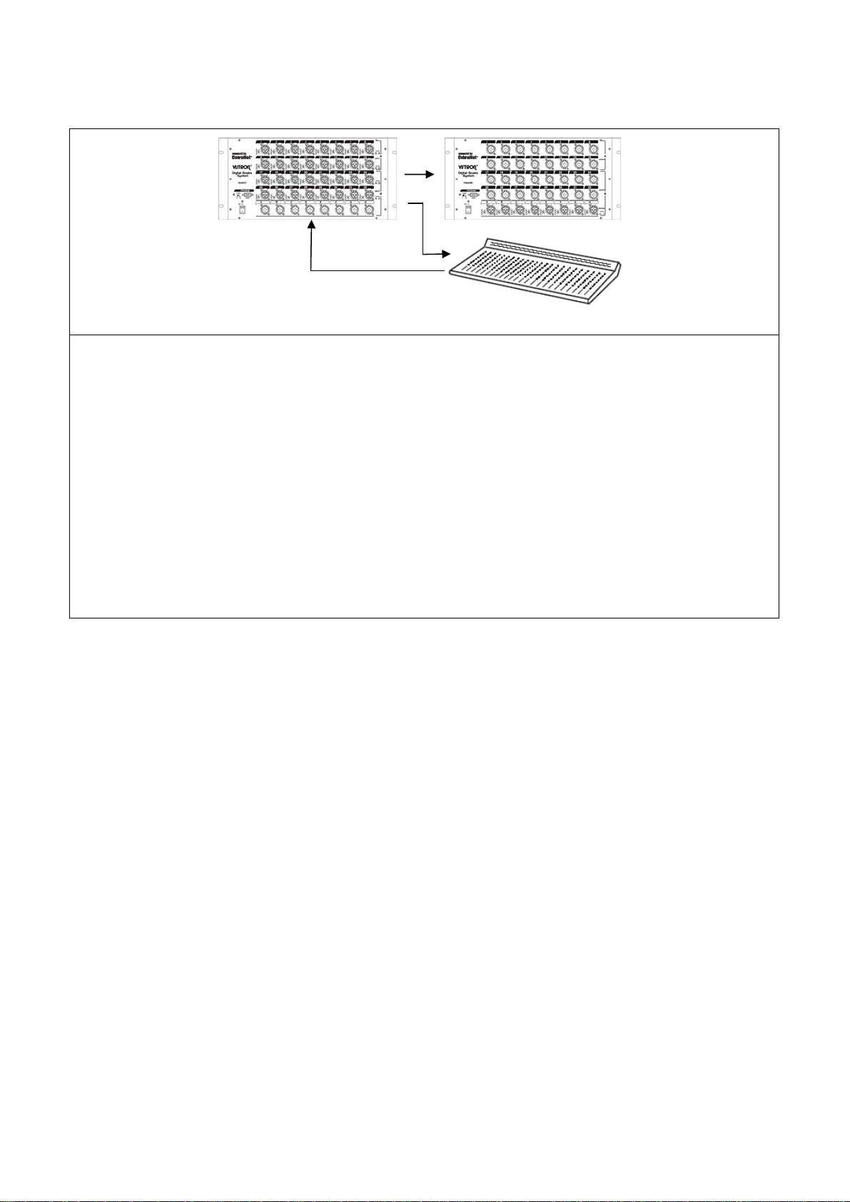
•DIAGRAM FOR BASIC 1:1 CONNECTION OF TRANSMITTER & RECEIVER •
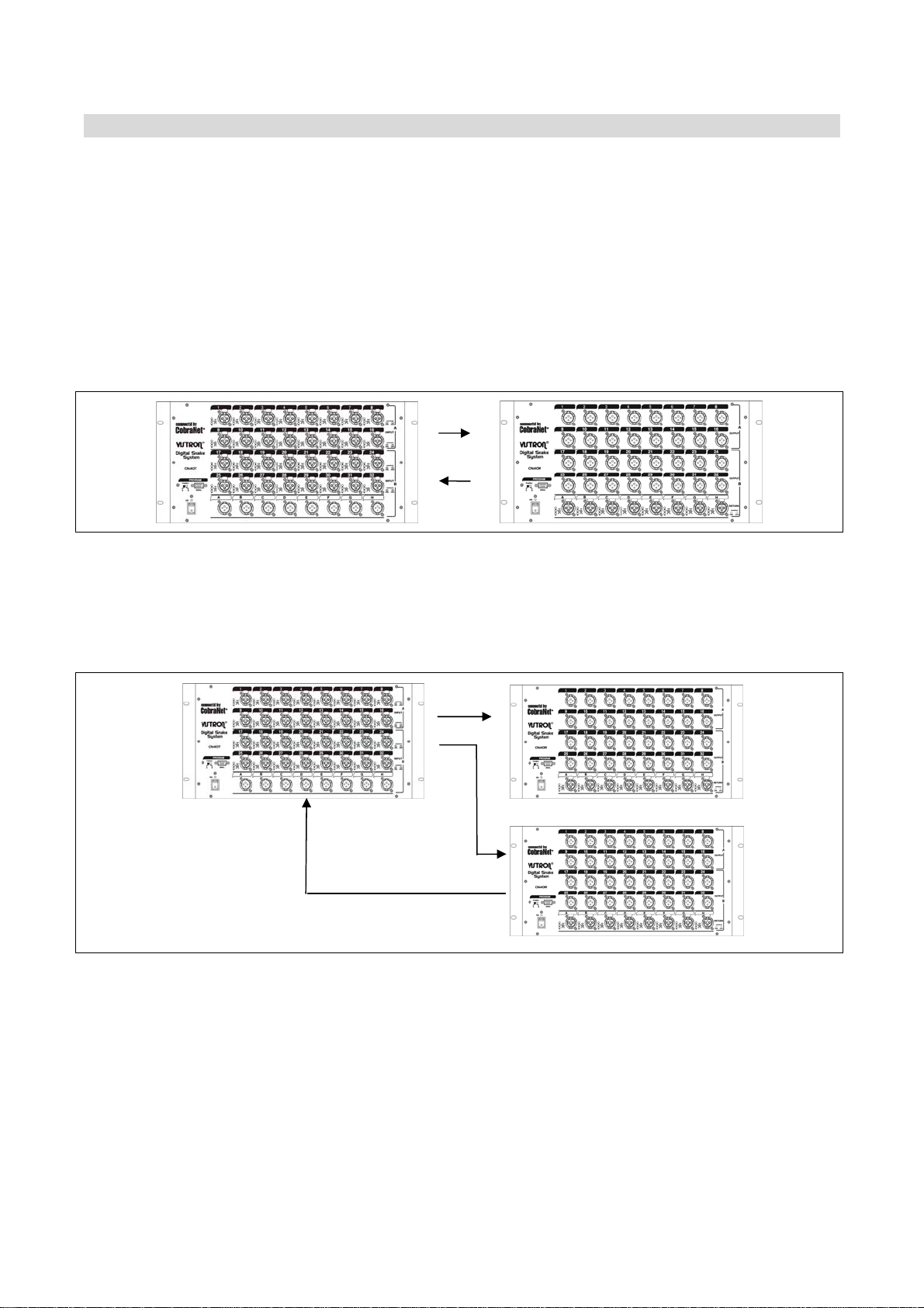
•HOW TO CONNECT THE TRANSMITTER & RECEIVER (1:1) •
OUT (SEND) Part of TRANSMITTER & RECEIVER
STN40-Transmitter & STN40-Receiver are developed to transmit and receive the audio signal.
If we developed this equipment with only transmit function, it’s necessary several
equipments for transmit from Stage to Monitor Room and from Monitor Room to Stage, and
then the cost will be increased. So, we developed Digital Multi Cable STN40/24 Series with
CobraNet Program. Our STN40/24 Series is used OUT(SEND) Terminal for Signal Return and
it’s available to Receive the Signal in Transmitter.
Case of Connection for Transmitter and Receiver (1: 1 Connection)
The Group Select Switch of Option Switch should be same and No.4 Switch should be turn-
on in first equipment and turn-off in second equipment. No.5 Switch should be turn-on for
both of equipment.
Case of Connection for Transmitter and Receiver (1:N Connection)
T 1 R1
R2
The Group Select Switch of Option Switch should be same and No.4 Switch should be turn-
on in T1 and turn-off in R1, R2. No.5 Switch should be turn-off in R1 and Turn-On in R2.
In case T:R is 1:N, the value of Channel of Out (Send) Parts of R1 & R2 is exceed in 8Ch of
Receivers of T1. In this case, the first Turn-On equipment between R1 & R2 can transmit the
signal to T1. To fix this setting, Turn-On Option Switch of Equipment which to be returned to
T1, and Turn-Off the Switch of the other equipment.
•DIAGRAM FOR 1: N CONNECTION OF TRANSMITTER & RECEIVERS •

HOW TO SET THE PROGRAM FOR 1:N CONNECTION
T 1 R1
R2
STN40-Transmitter & STN40-Receiver are developed to transmit and receive the audio signal.
If we developed this equipment with only transmit function, it’s necessary several equipments for
transmit from Stage to Monitor Room and from Monitor Room to Stage, and then the cost will be
increased.
So, we developed Digital Multi Cable STN40/24 Series with CobraNet Program. Our STN40/24 Series is
used OUT(SEND) Terminal for Signal Return and it’s available to Receive the Signal in Transmitter.
In case T:R is 1:N, the value of Channel of Out (Send) Parts of R1 & R2 is exceed in 8Ch of Receivers
of T1.
In this case, if there is no extra program setting, the first Turn-On equipment among R1 & R2 can
transmit the signal to T1. To fix this setting, it’s necessary to set using the Option Switch.
HOW TO SET R2 WHICH IS AVAILABLE TRANSMITTING AND RECEIVING
No. 1-3 Select Switch among Option Select Switches in the back side of equipment should be in
same position. No. 4 Select Switch should be Off for receiving, No. 5 Select Switch should be On for
Return. When we produce our equipment, the equipment is set to receive the normal channel and
transmit through OUT(SEND).
In case the connection of T:R is 1:N, it is available to set to transmit signal from only one equipment
among several Receivers and it is very convenient to get fixed value.
HOW TO SET R1 WHICH IS AVAILABLE RECEIVING AND NOT AVAILABLE TRANSMITTING
No. 1-3 Select Switch among Option Select Switches in the back side of equipment should be in
same position. In case of STN40RT, No.1-3 Select Switch should be in same position Select A of STN40T
& STN40R. Select B Switch of STN40T & STN40R also should be in same position.
At this time, Select A and Select B should be different.
No. 4 Select Switch should be Off for receiving, No. 5 Select Switch should be On for Return.
When we produce our equipment, the equipment is set to receive the normal channel and transmit
through OUT(SEND).
In case the connection of T:R is 1:N, it is available to set to transmit signal from only one equipment
among several Receivers and it is very convenient to get fixed value.

•DIAGRAM FOR 1:N CONNECTION WITH DIGITAL MIXER BUILT IN COBRANET •
HOW TO SET THE PROGRAM FOR 1:N CONNECTION WITH DIGITAL MIXER BUILT-IN COBRANET
T1 R1
M2 Digital Mixer built-in CobraNet
OUT (SEND) PART OF TRANSMITTER & RECEIVER
STN40-Transmitter & STN40-Receiver are developed to transmit and receive the audio signal.
If we developed this equipment with only transmit function, it’s necessary several equipments for
transmit from Stage to Monitor Room and from Monitor Room to Stage, and then the cost will be
increased. So, we developed Digital Multi Cable STN40/24 Series with CobraNet Program. Our
STN40/24 Series is used OUT(SEND) Terminal for Signal Return and it’s available to Receive the Signal
in Transmitter.
In case T:R is 1:N, the value of Channel of Out (Send) Parts of R1 & R2 is exceed in 8Ch of Receivers
of T1. In this case, if there is no extra program setting, the first Turn-On equipment among R1 & M2
can transmit the signal to T1.
To fix this setting, it’s necessary to set using the Option Switch.
HOW TO SET M2 WHICH IS AVAILABLE TRANSMITTING AND RECEIVING
For the Digital Mixer built-in CobraNet, it is available to set Transmitting and Receiving using PC which
is installed CobraNet Discovery Program provided by CIRRUS LOGIC.
Most of Digital Mixer built-in CobraNet is set to be available Transmitting and Receiving and there is
no need to set.
If the Digital Mixer built-in CobraNet is set only for Receiving function, please use above program to
set for Transmitting and Receiving.
HOW TO SET R1 WHICH IS AVAILABLE RECEIVING AND NOT AVAILABLE TRANSMITTING
No. 1-3 Select Switch among Option Select Switches in the back side of equipment should be in
same position.
In case of STN40RT, No.1-3 Select Switch should be in same position Select A of STN40T & STN40R.
Select B Switch of STN40T & STN40R also should be in same position.
At this time, Select A and Select B should be different.
No. 4 Select Switch should be Off for receiving, No. 5 Select Switch should be Off to prevent Return.
When we produce our equipment, the equipment is set to receive the normal channel and transmit
through OUT(SEND).
In case the connection of T:R is 1:N, it is available to set to transmit signal from only one equipment
among several Receivers and it is very convenient to get fixed value.
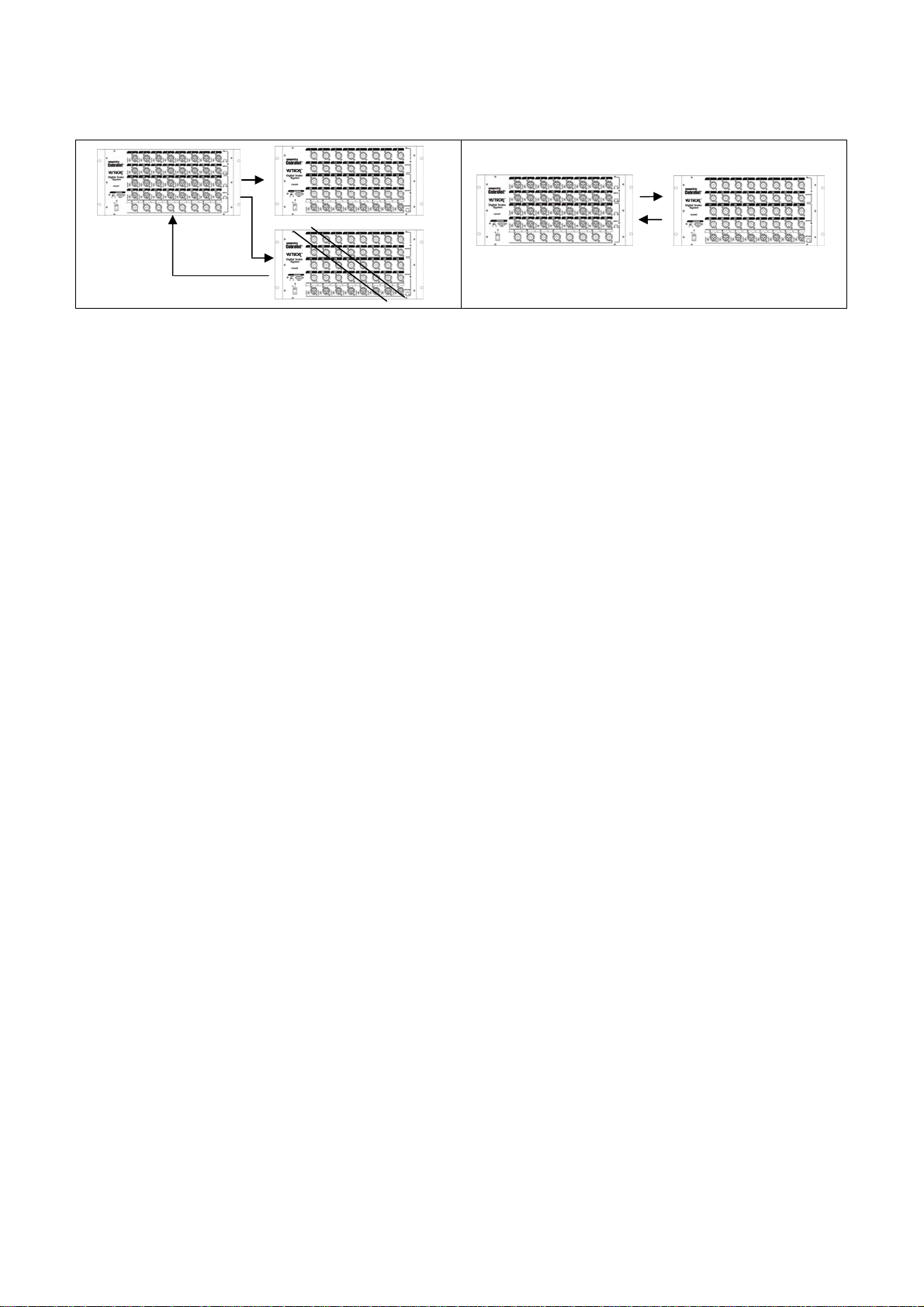
HOW TO CHANGE THE ONLY RECEIVING SETTING TO RECEIVING & TRANSMITTING SETTING
T1 R1
R2
T1 R1
HOW TO CHANGE THE SETTING OF RECEIVING & NO-TRANSMITTING TO SETTING OF RECEIVING &
TRANSMITTING
No. 1-3 Select Switch among Option Select Switches in the back side of equipment should be in
same position.
In case of STN40RT, No.1-3 Select Switch should be in same position Select A of STN40T & STN40R.
Select B Switch of STN40T & STN40R also should be in same position.
At this time, Select A and Select B should be different.
No. 4 Select Switch should be Off for receiving, No. 5 Select Switch should be On for Return.
When we produce our equipment, the equipment is set to receive the normal channel and transmit
through OUT(SEND).
In case the connection of T:R is 1:N, it is available to set to transmit signal from only one equipment
among several Receivers and it is very convenient to get fixed value.
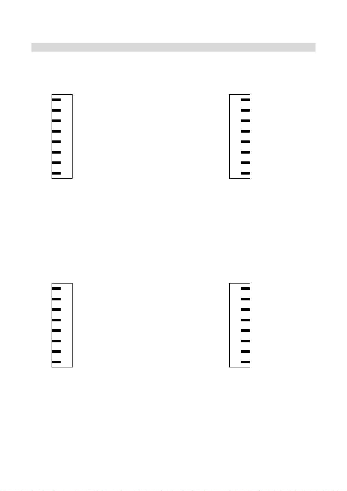
•RECOMMENDATION FOR CONNECTION / RECOMMENDATION OF UTP CABLE •
RECOMMENDATION OF UTP CABLE
We recommend to use UTP Cable (CAT-5) for our equipment.
1:1 UTP CABLE
8 BROWN ORANGE-WHITHBAND 1
7 BROWN-WHITEBAND ORANGE 2
6 BLUE BLUE-WHITEBAND 3
5 GREEN-WHITHBAND GREEN 4
4 GREEN GREEN–WHITEBAND 5
3 BLUE--WHITHBAND BLUE 6
2 ORANGE BROWN-WHITEBAND 7
1 ORANGE-WHITHBAND BROWN 8
When you make the UPT Cable, you can select your prefer color.
No. 1,2 of RJ-45 Connector should be use the cable for Transmitting, and No 3,6 should be
used the cable for Receiving.
In cae the connection of 1:1, the cable connection of No. 1,2 and No. 3,6 should be same.
Please pay attention in cable connection.
The color of normal using cable is as above.
The recommended longest length of cable which recommended in Ethernet Protocol is 100
Meters.
CROSS UTP CABLE [AVAILABLE / BASIC 1:1 CONNECTION]
8 BROWN BLUE-WHITHBAND 1
7 BROWN-WHITEBAND BLUE 2
6 BLUE ORANGE-WHITEBAND 3
5 GREEN - WHITH BAND GREEN 4
4 GREEN GREEN – WHITE BAND 5
3 BLUE--WHITHBAND ORANGE 6
2 ORANGE BROWN-WHITEBAND 7
1 ORANGE-WHITHBAND BROWN 8
When you make the UPT Cable, you can select your prefer color.
In case of Cross Cable, No. 1,2 of RJ-45 Connector should be use the cable for Transmitting,
and No 3,6 should be used the cable for Receiving.
Both end of cable of Transmitting and Receiving should be connected in cross.
The color of normal using cable is as above.
The recommended longest length of cable which recommended in Ethernet Protocol is 100
Meters.
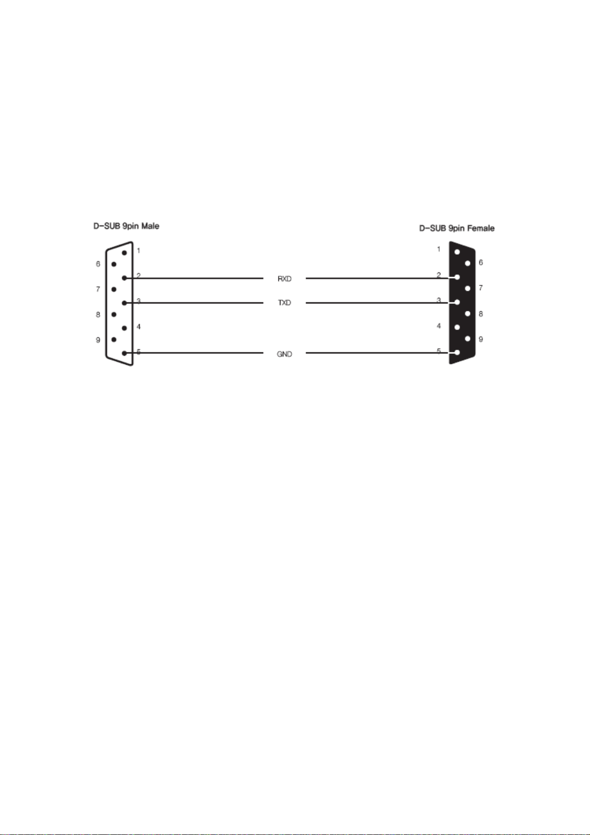
SERIAL RS-232 CABLE
Please use Cable for RS-232.
No. 2,3,5 of D-SUB 9pin Male and D-SUB 9pin Female should be connected directly.
The diagram for Connection is as below.
In case there is no 9 PIN Serial Port on the PC, please buy Adaptor and install the driver.
And then the computer recognizes the Serial Port.
RECOMMENDATION OF HUB
We recommend using Switching HUB over 100MBPS.
If you use Dummy HUB instead of Switching HUB, it may be caused reducing transfer speed
and decreasing sound quality.
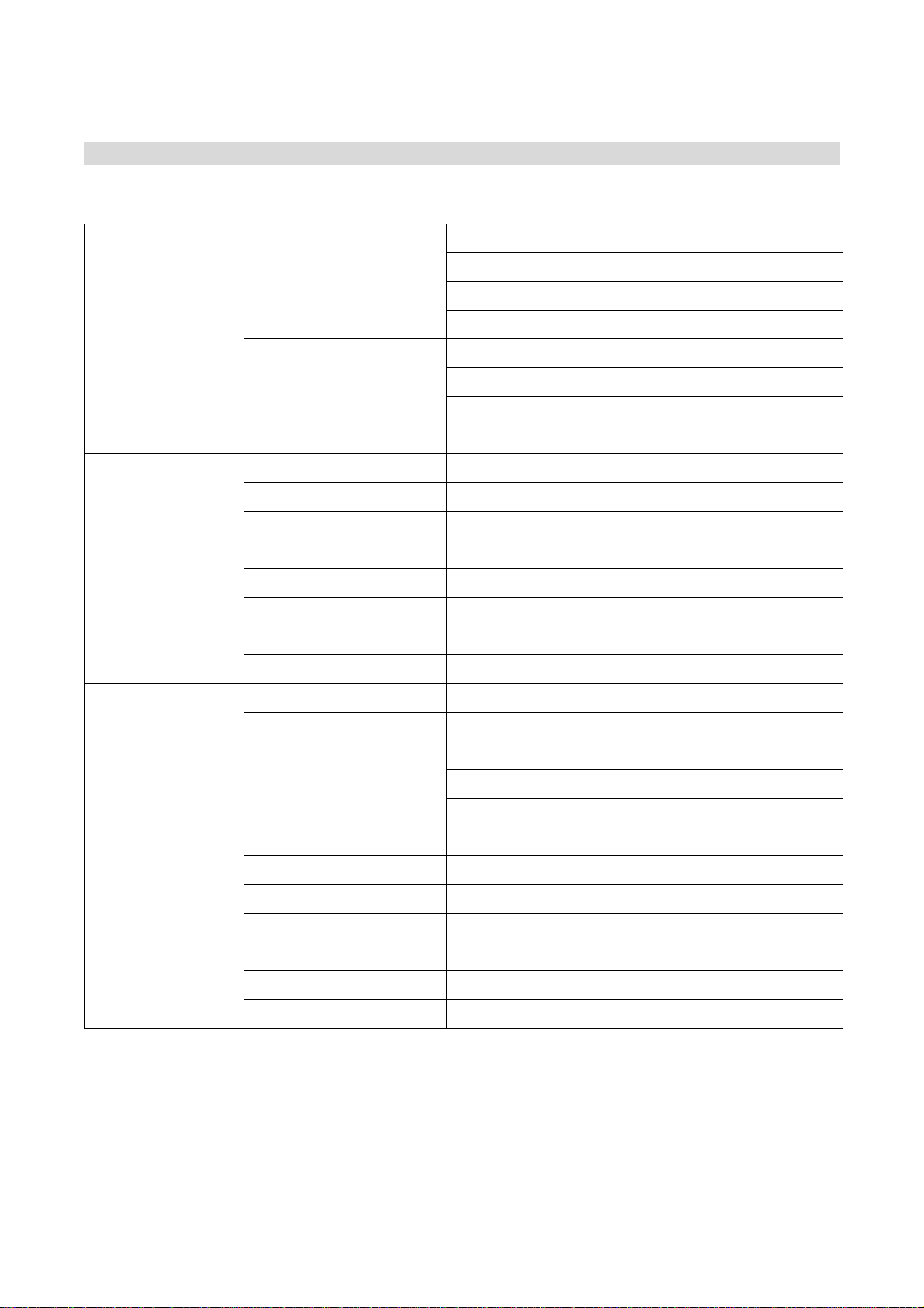
•SPECIFICATION •
CN40T [Transmitter]
Digital Parts
A/D Conversion
Sample Rate 32KHz ~ 192KHz
Bit Rate 24bit
Dynamic Range 114dB
THD+N -100dB
D/A Conversion
Sample Rate 32KHz ~ 216KHz
Bit Rate 24bit
Dynamic Range 114dB
THD+N -105dB
TECHNICAL DATA
Sample Rate 48KHz
Latency 1 1/3mS, 2 2/3mS, 5 1/3mS
THD <0.008% @1KHz 0dB input
Frequency Response 20 ~ 20KHz @+/-0.5dB,
Dynamic Range 110dB
Noise Floor <-95dB @0dB Gain
Cross Talk <-95dB @0dB Gain
Ethernet 100Base-T CAT-5 Cable max 100M
Specification
Channel 32IN, 8OUT(Send) XLR Jack
Indicate
Signal Input LED
Phantom Power LED
Clipping LED
Power Switch LED
Phantom Power Switch ON/OFF
Input Range +30dB ~ -30dB @ Analog Channel
Input Select Switch Analog XLR
PC Control A1-16, B17-32CH RS-232 Group Control
Ethernet 100Base-T RJ45 XLR Connector
Weight 9.5Kg
Dimension 480(W) x 220(H) x 271(D)

CN40 R [Receiver]
Digital Parts
A/D Conversion
Sample Rate 32KHz ~ 192KHz
Bit Rate 24bit
Dynamic Range 114dB
THD+N -100dB
D/A Conversion
Sample Rate 32KHz ~ 216KHz
Bit Rate 24bit
Dynamic Range 114dB
THD+N -105dB
TECHNICAL DATA
Sample Rate 48KHz
Latency 1 1/3mS, 2 2/3mS, 5 1/3mS
THD <0.008% @1KHz 0dB input
Frequency Response 20 ~ 20KHz @+/-0.5dB
Dynamic Range 110dB
Noise Floor <-95dB @0dB Gain
Cross Talk <-95dB @0dB Gain
Ethernet 100Base-T CAT-5 Cable max 100M
Specification
Channel 8IN, 32OUT(Return) XLR Jack
Indicate
Signal Input LED
Phantom Power LED
Clipping LED
Power Switch LED
Phantom Power Switch ON/OFF
Input Range +30dB ~ -30dB @ Analog Channel
Input Select Switch Analog XLR
PC Control A1-16, B17-32CH RS-232 Group Control
Ethernet 100Base-T RJ45 XLR Connector
Weight 9.5Kg
Dimension 480(W) x 220(H) x 271(D)

CN24 T [Transmitter]
Digital Parts
A/D Conversion
Sample Rate 32KHz ~ 192KHz
Bit Rate 24bit
Dynamic Range 114dB
THD+N -100dB
D/A Conversion
Sample Rate 32KHz ~ 216KHz
Bit Rate 24bit
Dynamic Range 114dB
THD+N -105dB
TECHNICAL DATA
Sample Rate 48KHz
Latency 1 1/3mS, 2 2/3mS, 5 1/3mS
THD <0.008% @1KHz 0dB input
Frequency Response 20 ~ 20KHz @+/-0.5dB
Dynamic Range 110dB
Noise Floor <-95dB @0dB Gain
Cross Talk <-95dB @0dB Gain
Ethernet 100Base-T CAT-5 Cable max 100M
Channel 16IN, 82OUT(Send) XLR Jack
Specification
Indicate
Signal Input LED
Phantom Power LED
Clipping LED
Power Switch LED
Phantom Power Switch ON/OFF
Input Range +30dB ~ -30dB @ Analog Channel
Input Select Switch Analog XLR
PC Control RS-232 Control
Ethernet 100Base-T RJ45 XLR Connector
Weight 8.5Kg
Dimension 480(W) x 136(H) x 271(D)
This manual suits for next models
4
Table of contents


