Idview Digital E-P132-X User manual


Table of Contents
Introduction …………………...………………………………………………4
Overview …………………………………………………………………………... 5
Package Checklist ………………………………………………………………….6
Block Diagram ……………………………………………………………………..7
Product Features …………………………………………………………………. 8
Product Specifications ……………………………………………………………. 9
Converter Description & Installation ………………………………… 11
Product Panel Views ………………………………………………………………11
Left Side …………………………………………………………………………… 12
Right Side …………………………………………………………………………..13
LED Indicators …………………………………………………………………….14
Terminator & Reset Button ……………………………………………………… 15
Wiring Architecture ……………………………………………………………….16
RS-232 ……………………………………………………………………………... 16
RS-422/RS-485 ……………………………………………………………………..17
Converter Configuration ………………………………………………….18
2

Initial IP Configuration …………………………………………………………...18
Device Management Utility of ETM ……………………………………………...19
Menu “View” ………………………………………………………………………20
Menu “Config” ……………………………………………………………………. 20
Web Console Configuration ………………………………………………………22
Controller Status …………………………………………………………………..23
Controller Setup …………………………………………………………………...25
Controller Updated ………………………………………………………………..31
Factory Default Setting ……………………………………………………………32
Self-Testing ……………………………………………………………………. 33
Hyper Terminal for TCP/IP WinSock …………………………………………...34
Hyper Terminal for COM Port ………………………………………………….. 372
Data Transmission ………………………………………………………………... 37
Appendix A - FAQ ………………………………………………………….. 38
Appendix B - Pin Outs and Cable Wiring ………………………………………. 39
DC Power Outlet ………………………………………………………………….. 39
RJ-45 Pin Assignment ……………………………………………………………. 39
RS-232 Pin Assignment ……………………………………………………………39
RS-485 Pin Assignment …………………………………………………………. 39
3

Introduction
We are providing new ways of connecting serial devices to a Local Area Network (LAN)
or Wide Area Network (WAN). E-P132-X TCP/IP converter is designed to operate serial
ports over 10/100M Ethernet networks. The data is transmitted via TCP/IP protocol.
Therefore control is available via Ethernet, Intranet and Internet. E-P132-X TCP/IP
converter is packaged in a aluminum case well suited for industrial environments. All
serial ports operate in common RS-232 mode , industrial RS-422 and RS-485 modes
configuration.
E-P132-X TCP/IP converter series is a low-cost, high performance design. By careful
selecting high quality with competitive prices components in the world, E-P132-X
makes network connectivity possible with affordable cost for virtually all kinds of serial
devices.
The following topics are covered in this chapter:
◎Overview
◎Package Checklist
◎
◎
◎Block Diagram
◎
◎
◎Product Features
◎
◎
◎Product Specifications
4

Overview
E-P132-X TCP/IP converter is designed to make your serial devices Internet ready
instantly. ARM-7 Series of E-P132-X TCP/IP converter makes them the ideal
choice for connecting your RS-232 or RS-422/485 serial devices—such as PLCs,
meters, and sensors to an IP-based Ethernet LAN, making it possible for your
software to access serial devices anywhere and anytime over a local LAN or the
Internet.
ARM-7 Series converter ensures the compatibility of network software that uses a
standard network API (Winsock or BSD Sockets) by providing TCP Server Mode,
TCP Client Mode, and UDP Mode. ARM-7 Series’ Virtual COM driver, software that
works with COM port can be set up to work over a TCP/IP network in no time. This
excellent feature preserves your software investment and lets you enjoy the benefits
of networking your serial devices instantly.
ARM-7 Series converter supports manual configuration via the handy web browser
console and many protocols including TCP, IP, UDP, HTTP, DHCP, ICMP, and ARP. It
is the best solution to network your serial devices.
5

Package Checklist
ARM-7 product is shipped with the following items:
1 unit of E-P132-X TCP/IP converter
1 unit of Power Adaptor (9V~12V DC, 500mA)
Documentation & Software CD
NOTE: Notify your sales representative if any of the above items is missing or
damaged.
6

Block Diagram
Low-cost devices usually are equipped with low speed processors and limited
memories. In reality, they are neither having the capability nor practicality to manage
complicated network TCP/IP protocols. ARM-7 Series is a low cost while providing
high performance network solution by converting data stream between network
TCP/IP and popular serial port signals. In stead of processing TCP/IP packets
directly, devices need only deal with those interface signals, which greatly simplifies
the complexity of TCP/IP network in linkage.
7

Product Features
□
□
□Data Conversion between RS-232/422/485 and Ethernet
Convert serial device (RS-232, RS-422, RS-485) data/signal into the TCP/IP
package data/signal and send them out with the Ethernet DataStream; or convert
the TCP/IP package data/signal into serial device data/signal.
□
□
□Dynamic IP Configuration
Support DHCP client mode, simplifying network address configuration and
management.
□
□
□Dual LAN Speed
Support 10/100 Mbps Ethernet, auto-detected.
□
□
□Server / Client Dual Modes
ARM-7 Series can be configured as network server or network client. In the client
mode, it can be installed in network which is protected by NAT router or firewall,
without the need of a real IP address.
□
□
□Web-based Setup
Parameters setup is based on HTTP protocol by using standard browsers (IE and
Netscape). No special software would be required.
□
□
□Built-in Security Control
Protected by setup password to prevent intruders.
□
□
□Firmware Remote Update
Firmware can be updated directly via Ethernet network to keep up with latest
network standards.
8

Product Specifications
CPU : 32-bits ARM-7 CPU , 25 MHz
RAM : 2 M Bytes SDRAM ( 1 M * 16Bits )
ROM : 128 K Bytes Flash ROM
Ethernet
Port Type : RJ-45 Connector
Speed : 10 /100 M bps ( Auto Detecting )
Protocol : ARP , IP , ICMP , UDP , TCP , HTTP , DHCP
Protocol (Optional):PPPoE , PPPoM
Mode : TCP Server / TCP Client / UDP
Setup : HTTP Browser Setup (IE & Netscape) , RS-232 Console
Security : Setup Password
Protection : Built-in 1.5KV Magnetic Isolation
9

Serial Port
Port : RS-232 * 1 Port ,RS-422/RS-485 * 1 Port
Speed:300 bps~230.4 K bps
Parity:None , Odd , Even , Mark , Space
Data Bit:5 , 6 , 7 , 8
Stop Bit : 1 , 2
RS-232 Pins : Rx , Tx , GND , RTS , CTS , DTR , DSR , DCD
RS-422 : Rx+ , Rx- , Tx+ , Tx- (Surge Protect)
RS-485 : Data+ , Data- (Surge Protect)
Built –in RS-422/RS-485 Terminal Resistor
15KV ESD for all signals
Watch Dog Function
Power : DC 9 – 12 V , 500mA
Led Lamp : SYS (PWR) , LAN , Rx , Tx
Environment : Operating Temperature: 0℃~50℃
Storage Temperature : -10℃~70℃
Dimensions : 110 * 90 * 30 mm ( W * D * H )
Weight : 146 gm
10

11
Converter Description
Product Panel View
Reset Button
RS-422 / 485 Terminator
DC-In
Power Outlet Serial Port
RS-232
LAN Serial Port
RS-485/RS-422
LED Indicators

12
Left Side
Power Supply
The E-P132-X TCP/IP converter is powered by a single 9 ~12V DC(Inner
positive/outer negative) power supply and 500mA of current. A suitable power
supply adapter is part of the packaging. Connect the power line to the power outlet
at the left side of E-P132-X TCP/IP converter and put the adapter into the socket. If
the power is properly supplied, the “SYS” red color LED will be blink each time in
one second.
LAN Port
DC-In
Power Outlet
LAN
The connector for network is the usual RJ45. Simply connect it to your network
switch or Hub. When the connection is made, the LAN LED indicator will light.
When data traffic occurs on the network, red Tx & Rx LED indicator will blink during
data transferring and receiving.

13
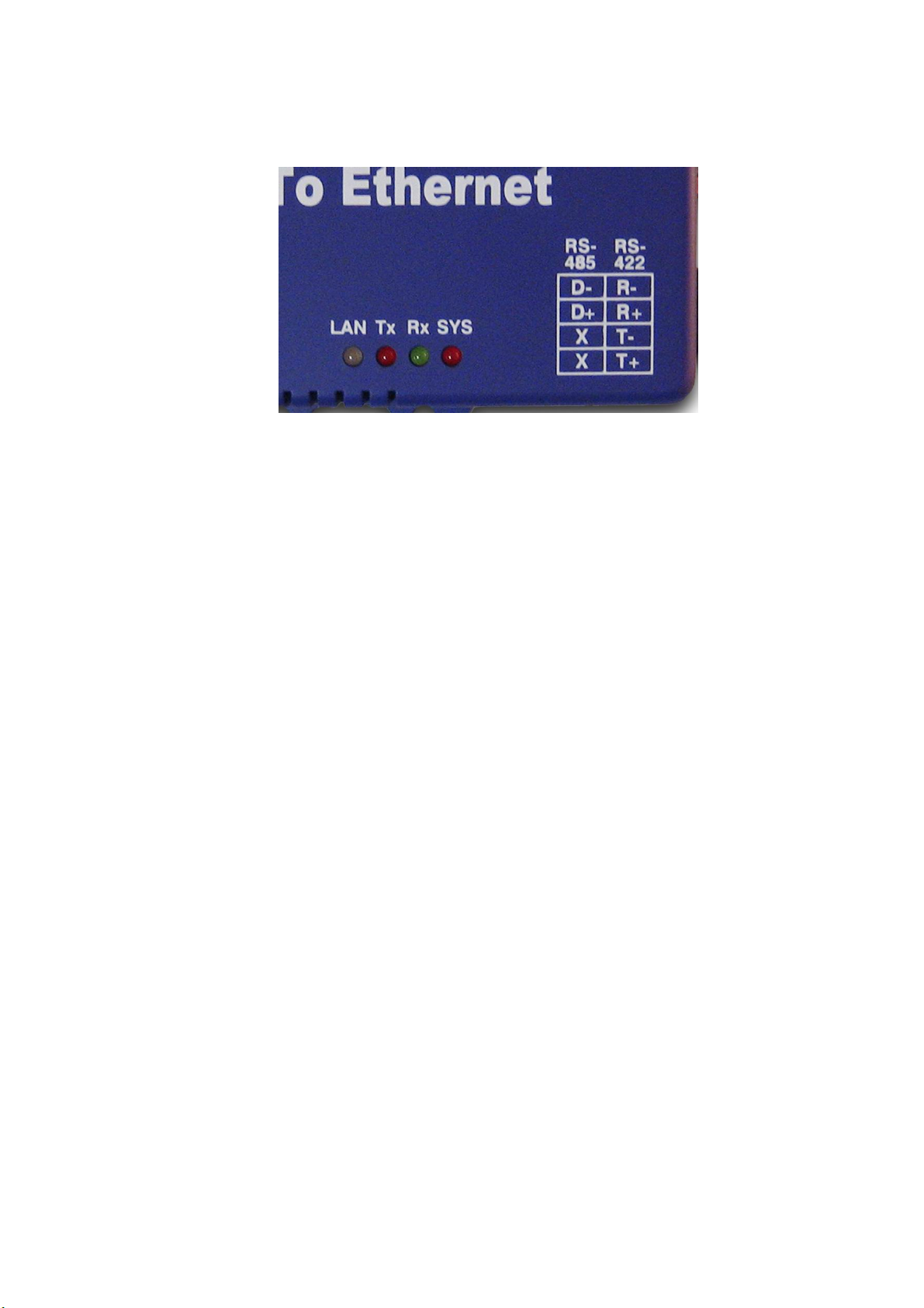
Right Side
RS-232
RS-422 / 485
Serial Port of RS-232/RS-422/RS-485
Connect the serial data cable between the converter and the serial device. Follow
the setup procedure to configure the parameters of the converter. (see the following
chapters ).
14
LED Indicators
SYS “Red LED”: Power indicated (when the power is on the LED will flash each
time in one second )
Rx “Green LED”: Network signal receiving indicated (when receive any signal
form network the LED will flash)
Tx “Red LED”: Network signal transforming indicated (when transmit any signal to
network the LED will flash)
LAN “LED”: On-line indicated (when converter link to LAN then the LED will keep
on)100M- Green LED、10M- Red LED

15
Terminator & Reset button
TerminatorReset Button
Resent Button
Press the button then turn on the power and waiting for 3 seconds. Converter will
reset to factory default.
Terminator
There is terminator resistor built in. If the switch 1 & 2 are set in “ON” position , 120
Ohm resistor is connected between the signals.

16
Wiring Architecture
RS-232 Wiring Architecture

17
RS-422 / RS-485 Wiring Architecture
When you finish the steps mentioned above and the LED indicators are as shown,
the converter is installed correctly. You can use the Setup Tool “ETM.exe” to
setup the IP Address.
To proceed the advanced parameters setup, please use a web browser (IE or
Netscape) to continue the detailed settings.

18
Converter Configuration
Initial IP Configuration
When setting up your converter for the first time, the first thing you should do
configure the IP address. This chapter introduces the method to configure the
device server’s IP address. For more details about network settings, see “Web
Console Configuration”. in next sub section.
For quick setup of converter , We suggest you to reference “Quick
Installation Guide” manual.
The following topics are covered in this chapter:
◎
◎
◎
Device Management Utility
◎
◎
◎
Menu “View”
◎
◎
◎
Menu “Config”

19
Device Management Utility
On PC we provide a Device Management Utility named ETM.exe which is an
executable program in Windows 32 bit environments. ETM Setup Tool is used to
detect and setup the installed converters. It uses UDP broadcast packets to query
and configure converters on the network.
When you activate the tool, it will detect the existence of the installed converters
and depict the converters’ status such as IP address, Subnet Mask, MAC Address,
and Device ID (see Figure 3.1).
If your computer OS is Windows XP version which means “WINDOWS Firewall”
function in OS is activated. However ETM.exe wouldn’t detect the converter’s IP
address, therefore, You have to temperately disable “WINDOWS Firewall” function.
After finishing the parameters settings, You can restart “WINDOWS Firewall”
function.
Due to the nature of broadcast UDP packets, ETM has following characteristics:
□
□
□Broadcast packets aren’t limited by subnet. Even if the IP address of the
converters and the computer running ETM do not belong to the same subnet, it still
works fine.
□
□
□Broadcast packets can not pass routers. ETM can only be used to monitor
devices with computer running ETM in the same segment of local area network
.
(Figure 3.1)

20
Menu “View”
□
□
□View -> Refresh F5
Refresh the status. ETM will send another query to get updated information.
(see Figure 3.2).
Note: Always run the “View-> Refresh” after any data change.
(Figure 3.2)
(
(Figure3.2)
View -> Exit Alt+F4
Exit from the program (see Figure 3.2 ).
Menu “Config”
Config -> IP Address (see Figure3.3)
(Figure 3.3)
( Figure3.3)
Table of contents
Popular Media Converter manuals by other brands


Motrona
Motrona FM210 operating manual

HEIDENHAIN
HEIDENHAIN ERN 1385 Mounting instructions

Danfoss
Danfoss iC7 Series installation guide

Ensemble Designs
Ensemble Designs BrightEye 30 user guide

Cyrus
Cyrus DAC X User instructions

AJA Video Systems Inc
AJA Video Systems Inc IPT-10G2-SDI Installation and operation guide