VitalWell VW801 User manual

V
V
i
i
t
t
a
a
l
l
W
W
e
e
l
l
l
l
E
E
l
l
e
e
c
c
t
t
r
r
o
o
n
n
i
i
c
c
s
s
P
P
t
t
e
e
L
L
t
t
d
d
.
.
Tel:+86-0756-3867295
Block D3,#415/416, SouthernSoftwarePark,TangJia,
,
Z
Zh
hu
uH
Ha
ai
i,
,
C
Ch
hi
in
na
a
5
51
19
90
08
80
0
vital-well.com
VW801
VW802
VW803
VW804
Serial-WiFiModem UserManual(Rev. 1.0)
OverviewofCharacteristics
²SupportIEEE802.11b/g/nWireless Standards
²Built-inUSB-SerialBridgeChip(SilabsCP2102)
²SupportATcommandssending fromserialport
²SupportconnectionsoverATcommands
²Supporttransparentmode(serial<->wifi)
²SupportSTA/AP/AP+STAModes
²SupportWPSfunctions
²SupportautomaticallyDDNSconnections
²Basedon High performance MCU
²High sensitivity, Long range
²SupportMulti-TCPLink(5Channel)Application
²VariableInterfaces:USB(VirtualCOM), RS485,232TTL, RS232
²OnboardPCB Antenna

V
V
i
i
t
t
a
a
l
l
W
W
e
e
l
l
l
l
E
E
l
l
e
e
c
c
t
t
r
r
o
o
n
n
i
i
c
c
s
s
P
P
t
t
e
e
L
L
t
t
d
d
.
.
Tel:+86-0756-3867295
Block D3,#415/416, SouthernSoftwarePark,TangJia,
,
Z
Zh
hu
uH
Ha
ai
i,
,
C
Ch
hi
in
na
a
5
51
19
90
08
80
0
vital-well.com
TABLEOFCONTENTS
1. PRODUCTOVERVIEW..............................................................................................................1
1.1. GeneralDescription ..........................................................................................................1
1.1.1.DeviceFeatures......................................................................................................1
1.1.2.Specifications..........................................................................................................2
1.1.3.KeyApplication .......................................................................................................2
1.2. HardwareIntroduction.......................................................................................................3
1.2.1.PinsDefinition .........................................................................................................3
2. FUNCTIONALDESCRIPTION....................................................................................................5
2.1.Wireless Networking.........................................................................................................5
2.1.1.BasicWireless NetworkBasedOnAP (Infrastructure)............................................5
2.1.2. Wireless NetworkBasedOnAP+STA.....................................................................5
2.2. OperateMode :Transparent TransmissionMode .............................................................6
2.3. UARTFrameScheme.......................................................................................................7
2.3.1.UARTFree-Frame..................................................................................................7
2.3.2.UARTAuto-Frame..................................................................................................7
2.4. Encryption.........................................................................................................................8
2.5. ParametersConfiguration .................................................................................................8
2.6. SOCKETBFunction .........................................................................................................8
2.7. Multi-TCPLinkConnection................................................................................................9
3. OPERATIONGUIDELINE.........................................................................................................10
3.1. VW801/VW802/VW803/VW804Usage Introduction.....................................................10
3.1.1.SoftwareTools......................................................................................................10
3.1.2.NetworkConnection..............................................................................................10
3.1.3.DefaultParameterSetting..................................................................................... 11
3.1.4.ModemTest.......................................................................................................... 11
3.2. TypicalApplicationExamples..........................................................................................14
3.2.1. Wireless ControlApplication..................................................................................14
3.2.2.RemoteManagementApplication..........................................................................14
3.2.3.Transparent SerialPortApplication .......................................................................14
4. AT+INSTRUCTIONINTRODUCTION.......................................................................................16
4.1. ConfigurationMode.........................................................................................................16
4.1.1.SwitchtoConfigurationMode................................................................................16
4.2. AT+Instruction Set Overview...........................................................................................17
4.2.1.Instruction SyntaxFormat......................................................................................18
4.2.2.AT+InstructionSet.................................................................................................19
APPENDIXA: HTTPPROTOCOLTRANSFER.............................................................................37
A.1.HTTPATcommand ........................................................................................................37
A.2.HTTPExample...............................................................................................................39
APPENDIXB: Doument History..................................................................................................40

VW801, VW802,VW803,VW804Serial-WiFiModemUserManual
Vitalwell Electronics (Zhuhai)Pte.Ltd.www.vital-well.com email: Vitalwell@vital-well.com 1
1.PRODUCT OVERVIEW
1.1.General Description
VW801/2/3/4low-powerembeddedSerial-WiFimodemseriesprovidesawaytousethe popular
serialinterface(RS485,USBvirtualCOM,232TTL,RS232,)totransferdataoverWi-Fiwireless
networking.ThemoduleintegrateshardwareMAC,baseband chip,RFtransceiverunit, and a
poweramplifier;the embedded firmwaresupportsflexibleWi-Fiprotocols,TCP/IPprotocolstack,
aswell askindsofnetworkingconfiguration.
VW801modembuilt-inaUSB-Serialbridgechip,anintegrated801.11b/g/nWi-Fisubsystems.
ThroughVW801,alargenumberoftraditionalserialinterfacebasedapplicationscan easily
access/controlWi-Fienablednetworks/devices.
VW80xusestheindustry'slowest-powerembeddedstructure,targetingembeddedwifidata/control
applications,forthe instance,forexamplein:smarthome,wifilighting,wifisocket, smartgrid,
handhelddevices, personalmedical,industrialcontrol,IPsensors, etc.VW801seriesmodemsdo a
professionaloptimizationontheseapplications.
VW80xseriesintegrateall wififeaturesinacompactsizemeasureonly72mm x24mm x9mm.
Using aconvenient solidUSBconnector,allowingtheuserplugintotheuserendequipmenteasily.
Moduleisequippedwithbuilt-inPCBantenna, noexternalantennaneeds.
VW80xseriesmodemlookscleanandbeautiful,suitableforthe variousembeddedI.O.T
applications.
VW80xseriesincludethese4modelsmodem(interfacedifferent):
²VW801: USB VCOM
²VW802:232TTLinterface
²VW803: RS232Cinterface
²VW804: RS485 interface
1.1.1. Device Features
lSupportIEEE802.11b/g/nWireless Standards
lBuilt-inUSB-SerialBridgeChip(SilabsCP2102,VW801)
lVariousinterface:RS485,232TTL,RS232C, USB VCOM
lSupportATcommandssending fromserialport
lSupportconnectionsonATcommands
lSupporttransparent mode(serial<->wifi)

VW801, VW802,VW803,VW804Serial-WiFiModemUserManual
Vitalwell Electronics (Zhuhai)Pte.Ltd.www.vital-well.com email: Vitalwell@vital-well.com 2
lSupportSTA/AP /AP+STAModes
lSupportWPSfunctions
lSupportautomaticallyDDNSconnections
lBased onHighperformanceMCU
lHigh sensitivity, Longrange
lSupportMulti-TCPLink(5Channel)Application
lOnboardPCBAntenna
lCompact surfacemount module72mm x24mm x9mm
1.1.2. Specifications
Table1VW801 ModuleTechnicalSpecifications
Class Item Parameters
Certification FCC/CE
Wirelessstandard 802.11b/g/n
Frequencyrange 2.412GHz-2.484GHz
Transmit Power
802.11b: +16 +/-2dBm(@11Mbps)
Wireless 802.11g: +14 +/-2dBm(@54Mbps)
Parameters
802.11n: +13 +/-2dBm(@HT20, MCS7)
ReceiverSensitivity
802.11b: -93dBm(@11Mbps,CCK)
802.11g: -85dBm(@54Mbps,OFDM)
802.11n: -82dBm(@HT20,MCS7)
DataInterface USB/ RS485/232TTL
OperatingVoltage 4~5.5V
OperatingCurrent
Peak[ContinuousTX]:~200mA
Hardware Normal[WiFiON/OFF, DTIM=100ms]:
Parameters
Average. ~12mA, Peak:200mA
Standby:<200uA(Reserved)
OperatingTemp. -40 -85
StorageTemp.-45 -125
DimensionsandSize 72mm 24mm 9mm
NetworkType STA/AP/STA+AP
SoftwareSecurityMechanisms WEP/WPA-PSK/WPA2-PSK
Parameters
Encryption WEP64/WEP128/TKIP/AES
NetworkProtocol IPv4, TCP/UDP/FTP/HTTP
UserConfiguration AT+instructionset
1.1.3. KeyApplication
lSmart lighting, smart socket
lHomeautomation

VW801, VW802,VW803,VW804Serial-WiFiModemUserManual
Vitalwell Electronics (Zhuhai)Pte.Ltd.www.vital-well.com email: Vitalwell@vital-well.com 3
lIPsensors
lEmbeddedI.O.Tadd-onWIFI
lRemoteequipment monitoring
lAssettracking andtelemetry
lSecurity
lIndustrialsensorsandcontrols
lMedicaldevices
letc
1.2.HardwareIntroduction
Figure1.VW801/VW802/ VW803/VW804View
1.2.1. PinsDefinition
Figure2.VW801 PinsMap
(USB Atype,front view)
Table2VW801(USBVCOM)PinsDefinition
Pin1 2 3 4
Signal VCC D- D+ GND

VW801, VW802,VW803,VW804Serial-WiFiModemUserManual
Vitalwell Electronics (Zhuhai)Pte.Ltd.www.vital-well.com email: Vitalwell@vital-well.com 4
Table3VW802(232TTL)PinsDefinition
Pin1 2 3 4
Signal VCC RXD TXD GND
Table4VW803(232C)PinsDefinition
Pin1 2 3 4
Signal VCC RXD TXD GND
Table5VW804(RS485)PinsDefinition
Pin1 2 3 4
Signal VCC B A GND

VW801, VW802,VW803,VW804Serial-WiFiModemUserManual
Vitalwell Electronics (Zhuhai)Pte.Ltd.www.vital-well.com email: Vitalwell@vital-well.com 5
2.FUNCTIONALDESCRIPTION
Notesforsymbols:
AP:thatisthewireless Access Point, the founderofawireless networkand thecentreofthe
networknodes. Thewirelessrouterweuseathomeorinofficemaybe anAP.
STA:shortforStation,eachterminalconnectstoawireless network(suchaslaptops,PDAand
othernetworking devices)can becalled withaSTAdevice.
2.1.WirelessNetworking
VW801seriesmodemcanbeconfiguredasbothwireless STAandAP baseonnetworktype.Logically
therearetwointerfacesinVW801:STAorAP.When VW801operatesasAP,otherSTAequipments
areabletoconnecttoVW801 modemdirectly.Wireless networking withVW801seriesmodemisvery
flexible.
Inthefollowingdiagram,we’ll useVW801asexample.
2.1.1. BasicWireless NetworkBasedOnAP(Infrastructure)
Infrastructure:it’salsocalledbasicnetwork. It isbuiltonAPandmanySTAswhichjoinin.
The charactersofnetworkofthistypearethat APisthecentre,andall communicationbetween
STAsistransmittedthroughthe AP. Thefollowing figureshowsthistypeof networking.
Figure3.VW801 BasicWireless NetworkStructure
2.1.2. WirelessNetworkBasedOnAP+STA
VW801seriesmodemsupportAP+STAnetworkmode,meansVW801supportone AP interfaceand
oneSTAinterfaceatthesametime,asfollowingfigure,
VW801, VW802,VW803,VW804Serial-WiFiModemUserManual
Vitalwell Electronics (Zhuhai)Pte.Ltd.www.vital-well.com email: Vitalwell@vital-well.com 6
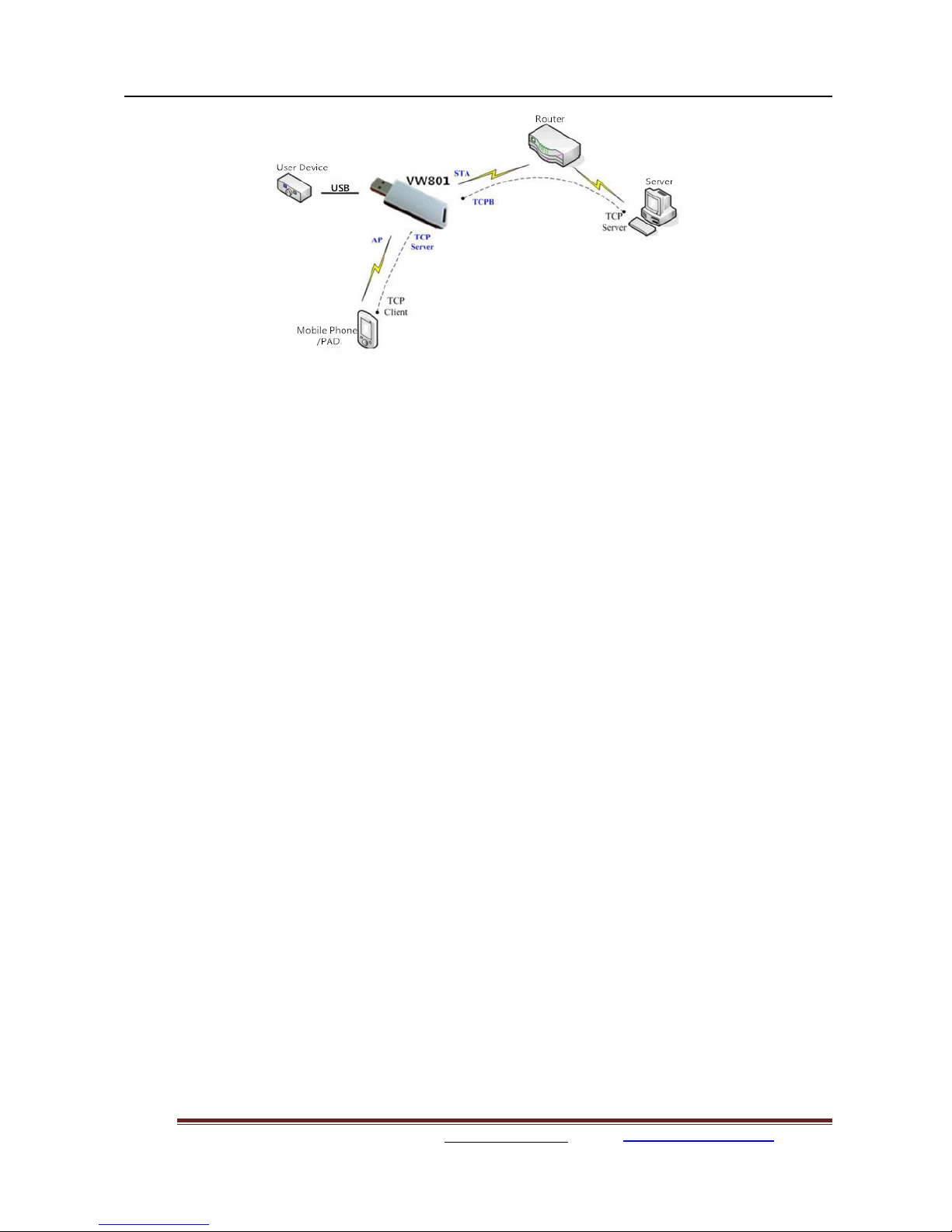
Figure4.VW801 AP+STANetworkStructure
When VW801modemenablesAP+STAfunction,Modem’sSTAinterfacecanconnectwithrouterand
thenconnect toTCPserverinthenetwork.Atthesametime,module’sAP interfaceisalsoactiveand
allowphone/PADtoconnectitthroughTCPB,thenphone/PADcancontrol/communicatewithVW801
andotherdeviceswithinthenetwork.
TheadvantageofAP+STAmodeis:
Userscaneasilycontroluserdevicethrough Phone/PAD,and no needchangingthe originalnetwork
setting.
Userscaneasilysetting modem’sparametersthroughWiFiwhenmoduleworksasSTAmode.
2.2.OperateMode:TransparentTransmissionMode
VW801modemsupport serialinterfacetransparent transmissionmode.
Inthismode,VW801functionsasaserial<->WIFIbridge,givesuserawireless serialportoverWIFI.
Usersjustonlyconfigurethenecessaryparameters.Afterpoweron,themodemwill automatically
connecttothe default wirelessnetwork/ server.
Wheninthismode,the modem'sserialportalways workinthetransparenttransmissionmode,users
can thinkitasavirtualwireless serialcable,andcan sendandreceivedataasusuallikeusing asimple
wired serialcable.Inotherwords,theoriginalserialcableondevicesisdirectlyreplacedwiththe
modem;userdevicescanthenbe easilyconverted towirelessenableddeviceswithoutanychanges.
The transparenttransmissionmode will fullycompatiblewithuser’soriginalsoftwareplatform and
reducethesoftwaredevelopmenteffortforintegratewirelessdatatransmission.
The parameterswhichneedtoconfigureinclude:
Wireless NetworkParameters
WirelessNetworkName(SSID)
SecurityMode
EncryptionKey

VW801, VW802,VW803,VW804Serial-WiFiModemUserManual
Vitalwell Electronics (Zhuhai)Pte.Ltd.www.vital-well.com email: Vitalwell@vital-well.com 7
TCP/UDPLinking Parameters
ProtocolType
LinkType(ServerorClient)
Target Port IDNumber
Target Port IPAddress
SerialPortParameters
Baud Rate
DataBit
Parity(Check)Bit
StopBit
FlowControl
2.3.UARTFrameScheme
2.3.1. UARTFree-Frame
VW801support UARTfree-framefunction. If userselectopenthisfunction, modulewill check the
intervalsbetweenanytwobyteswhenreceiving UARTdata.Ifthisintervaltimeexceedsdefinedvalue
(50msdefault),VW801will thinkitastheend ofone frameand transferthisfree-frametoWiFiport,
orVW801will receiveUARTdatauntil 1000bytes, thentransferthe1000 bytesframetoWiFiport.
VW801’sdefaultintervaltimesetting is50ms.Usercan alsosetthisintervalsomefaster(10ms)through
ATcommand.ButuserhavetoconsiderifuserMCU /applicationscansendall UARTdatacontinuously
within10msintervaltimerequirement,ortheUARTdatamaybe divideasfragment chocks.
ThroughATcommand:AT+UARTTE=fast/normal,usercan selectthe intervaltime:fast(10ms)and
normal(50ms).
2.3.2.UARTAuto-Frame
VW801support UARTauto-framefunction.Ifuserselect openthisfunctionandsettingauto-frame
triggerlengthandauto-frametriggertimeparameters, thenmodulewill autoframingthedatawhich
receivedfromUARTportand transmittingtothe networkaspre-defineddatastructure.
Auto-frametriggerlength:The fixeddatalengththatmoduleused totransmitting tothe network.
Auto-frametriggertime: Afterthetriggertime,ifUARTportreceiveddatacan’treachauto-frame
triggerlength, thenmodulewill transmittingavailabledatatothenetworkandbypassthe auto-frame
triggerlengthcondition.
DetailedUARTauto-framefunctioncan refertoAT+instructionset “UARTF/UARTFT/UARTFL”
introduction.

VW801, VW802,VW803,VW804Serial-WiFiModemUserManual
Vitalwell Electronics (Zhuhai)Pte.Ltd.www.vital-well.com email: Vitalwell@vital-well.com 8
2.4. Encryption
Encryptionisamethodofscramblingamessagethatmakesitunreadabletounwanted parties,adding
adegree ofsecurecommunications.Therearedifferentprotocolsforproviding encryption,and the
VW801modemsupportsfollowing:
WEP
WPA-PSK/TKIP
WPA-PSK/AES
WPA2-PSK/TKIP
WPA2-PSK/AES
2.5. ParametersConfiguration
VW801modemsupportsAT+ instruction set modeparameterconfiguration.AT+instruction set
configurationmeansuserconfigureparametersthroughserialinterfacecommand.
Referto “AT+instructionset”chapterformoredetail.
2.6. SOCKETBFunction
VW801supportdoublesocket communication,the socketBfunctionisdisabled bydefault.
Afterthemodemisready,send command “AT+SOCKB”tosettheconnection parameter, send
command “AT+TCPDISB=on”totrytoconnectwithTCPserver.Sendcommand “AT+TCPDISB=off”
tocloseconnection.Send command “AT+TCPLKB”toinquireTCPconnection.
Figure5.SocketBfunctiondemo

VW801, VW802,VW803,VW804Serial-WiFiModemUserManual
Vitalwell Electronics (Zhuhai)Pte.Ltd.www.vital-well.com email: Vitalwell@vital-well.com 9
2.7. Multi-TCPLinkConnection
WhenVW801modemconfiguredasaTCPServer,itsupportsMulti-TCPlinkconnection,and
maximum5TCPclientsareallowed.Usercanrealizemulti-TCPlinkconnection ateachoperation
mode.
Multi-TCPlinkconnectionwill workasfollowingstructure:
Upstream:All datesfromdifferentTCPconnectionorclientwill betransmittedtotheserialportasa
sequence.
Downstream:All datafromserialport(user)will be duplicateandbroadcasttoeveryTCPconnection
orclient.
Detailedmulti-TCPlinkdatatransitionstructureasfollowingfigure:
Figure6. Multi-TCPLinkDataTransitionStructure

VW801, VW802,VW803,VW804Serial-WiFiModemUserManual
Vitalwell Electronics (Zhuhai)Pte.Ltd.www.vital-well.com email: Vitalwell@vital-well.com 10
3. OPERATIONGUIDELINE
3.1. VW801/ VW802/ VW803/VW804UsageIntroduction
3.1.1. SoftwareTools
VW801usetwocommonsoftwaretoolsdebuggingandapplyingVW801modem.
(Usercanalsoselectothertoolsusedtodebug serialport).
SerialDebuggingSoftware: Terminal
Ethernet DebuggingSoftware: TCPtoserialclient software
3.1.2. NetworkConnection
UsercanselecttwomethodstoconnectVW801modembaseondedicatedapplication.
UseVW801 STAinterface. VW801 and debuggedPC2connecttoawireless AP,
AnotherPC1(oruserdevice)connecttoVW801modemwithserialport:
Figure7.STAInterfaceDebugConnection
UseVW801APinterface. DebugPC2connecttoVW801throughwireless connection,anotherPC1
(oruserdevice)connecttoVW801modemwithserialport.
Figure8.APInterfaceDebugConnection

VW801, VW802,VW803,VW804Serial-WiFiModemUserManual
Vitalwell Electronics (Zhuhai)Pte.Ltd.www.vital-well.com email: Vitalwell@vital-well.com 11
3.1.3. DefaultParameterSetting
DefaultSSID: VW801;
Default securitymode:open,none;
UserUARTparametersetting:115200,8,1,None;
Defaultnetworkparametersetting:TCP,Server,8899,10.10.100.254;
ModuleIPaddress:dhcp,0.0.0.0,0.0.0.0,0.0.0.0;
3.1.4. ModemTest
VW801builtinwithasilabsUSB-VCOMbridgechip:CP2102.Priortouseit,adriverisneededtobe
installed.Wecango toSilabswebsite www.silabs.com togetthelatestdriver.Alertlyacopyofthe driver
isputinthefollowinglink:
http://www.vital-well.com/webfile/software/CP210x_VCP_Windows.zip
whenthedriveriscorrectlyinstalled,afterpluggingVW801modem,avirtualCOMportwill becreated.
TofindtheCOMportnumberassignedbythesystem, youcan
Right-click theicon"MyComputer" ->”Properties”-> “Hardware"->"DeviceManager" ->"Ports(COM
&LPT)",(inourexampleitis COM8, the portnumberwill bedifferentdepending onthe PC)
Open HyperTerminalserialsoftwareTerminal,the portnumberfound inthe aboveselected portnumber
(eg COM8),
set:
Baudrate:115200(default is115200)
Databits:8
Parity: None
Stopbits:1
FlowControl: None
Click "Connet"

VW801, VW802,VW803,VW804Serial-WiFiModemUserManual
Vitalwell Electronics (Zhuhai)Pte.Ltd.www.vital-well.com email: Vitalwell@vital-well.com 12
Figure9. “Terminal”SerialDebug Tools
PC2(wifienabled)isconnectedtothe modemonwifiinterface, asshowninVW801.
Figure10. ComputersConnectedtoWifiModule
Click toopen“TCPUDPDbg”software.Click ,selectType:TCP,
DestIP:10.10.100.254,Port:8899,click “Create”.

VW801, VW802,VW803,VW804Serial-WiFiModemUserManual
Vitalwell Electronics (Zhuhai)Pte.Ltd.www.vital-well.com email: Vitalwell@vital-well.com 13
Figure11. "TCPUDPDbg"Creatingaconnection
Click on the leftpanel, inputdatainthesend window, click will send data
out.
Figure12. “TCPUDPDbg”ToolsConnection
AsVW801modulesupportstransparenttransmission modebydefault,soyoucan nowsend anydata
throughTerminaltoolbetweenPC1&PC2.Alltheprocedureisthesameasusing awiredserialcable
betweenthese2PCs.

VW801, VW802,VW803,VW804Serial-WiFiModemUserManual
Vitalwell Electronics (Zhuhai)Pte.Ltd.www.vital-well.com email: Vitalwell@vital-well.com 14
3.2.Typical Application Examples
3.2.1. WirelessControl Application
Figure13.WirelessControlApplication
Forthiswireless controlapplication,VW801 operatesasAP mode.Modem’sserialportconnectsto
userdevice.Then,acontrolagent(asmartphoneforthisexample)canmanage andcontroltheend
user’sdevicethroughthewireless connectionoverVW801modem.
3.2.2. RemoteManagementApplication
Figure14. RemoteManagementApplication
Forthisremotemanagementapplication,VW801works asSTAmodeandconnectstoInternetthrough
wireless AP.ModemconfiguredasTCPClientandcommunicateswithremoteTCPserverinInternet.
VW801serialport connectstouserdevice.
Thenthe userdevicewill becomeofaninternet enableddevice.You canthenaccessthedevice
anywhereintheworld.All you needisjust aninternetconnection.
3.2.3.TransparentSerial PortApplication
Forthistransparentserialportapplication,twoVW801modulesconnectasbelowfigurestobuildup

VW801, VW802,VW803,VW804Serial-WiFiModemUserManual
Vitalwell Electronics (Zhuhai)Pte.Ltd.www.vital-well.com email: Vitalwell@vital-well.com 15
atransparentserialportconnection.OneVW801operatesasAPmode,andthe otherVW801operates
asSTAmode. LettheSTAdeviceconnectstoAP.
Figure15. TransparentSerialPortApplication

VW801, VW802,VW803,VW804Serial-WiFiModemUserManual
Vitalwell Electronics (Zhuhai)Pte.Ltd.www.vital-well.com email: Vitalwell@vital-well.com 16
4. AT+INSTRUCTIONINTRODUCTION
4.1.ConfigurationMode
When VW801 powerup,itwill defaultoperatesastransparentmode,usercan switchtoconfiguration
modebysendingATcommandoverserialinterface.VW801UARTdefaultparameterssettingasbelow
figure,
Figure16. VW801Default UARTPortParameters
Inconfigurationmode, usercan setthemodemthroughAT+instructionset.
4.1.1. SwitchtoConfigurationMode
Twostepstofinishswitchingfromtransparenttransmission modetoconfigurationmode.
UARTinput +++”, aftermodulereceive +++”, andfeedback a”asconfirmation.
UARTinput a”,aftermodulereceive a”andfeedback +ok”togo intoAT+instruction set
configuration mode.
Figure17. SwitchtoConfigurationMode

VW801, VW802,VW803,VW804Serial-WiFiModemUserManual
Vitalwell Electronics (Zhuhai)Pte.Ltd.www.vital-well.com email: Vitalwell@vital-well.com 17
Notes:
1. “+++”and “a”shouldbeinputinacertainperiodoftimetomakethemoduleswitchtoconfiguration
mode(andshouldnot inacontinuousstream).Likethe following sequence.
2.When userinput “+++”(No “Enter”keyrequired), the UARTport will displayfeedback
information “a”,andnotdisplayinput information”+++”asaboveUARTdisplay.
3.AnyotherinputorwrongsteptoUARTportwill causethe modulestill works asoriginalmode
(Transparent transmission).
4.2.AT+InstructionSetOverview
UsercaninputAT+Instructionthroughhyperterminalorotherserialdebugterminal,alsocanprogram
theAT+Instructiontoscript.Usercanalsoinput “AT+H”tolistall AT+Instructionand description tostart.
Figure18. ”AT+H”InstructionforHelp

VW801, VW802,VW803,VW804Serial-WiFiModemUserManual
Vitalwell Electronics (Zhuhai)Pte.Ltd.www.vital-well.com email: Vitalwell@vital-well.com 18
4.2.1. InstructionSyntax Format
AT+Instruction protocolisbasedontheinstructionofASCII commandstyle,the descriptionofsyntax
formatasfollow.
FormatDescription
< >: Meansthepartsmustbe included
[]: Meanstheoptionalpart
Command Message
AT+<CMD>[op][para-1,para-2,para-3,para-4…]<CR>
AT+: Prefixof commandmessage;
CMD: Command string;
[op]: Symbolof commandoperator,
“=”: Thecommandrequiresparametersinput;
“NULL”: Querythecurrentcommandparameterssetting;
[para-n]: Parametersinputforsettingifrequired;
<CR>, <LF>: ”CarriageReturn ”Key, it’sASCII valueis0x0Aor0x0Dhexformat;
Notes: WheninputAT+Instruction, “AT+<CMD>”characterwill displaycapitalletterautomaticand
otherpartswill not change asyouinput.
ResponseMessage
+<RSP>[op][para-1,para-2,para-3,para-4…]<CR><LF><CR><LF>
+: Prefixofresponsemessage;
RSP: Responsestring;
“ok”: Success
“ERR”: Failure
[op] :=
[para-n]: Parametersif querycommandorErrorcodewhenerrorhappened;
<CR>: ASCII 0x0d;
<LF>:ASCIII0x0a;
ErrorCode
Table6ErrorCode Describtion
ErrorCode Description
-1 InvalidCommand
Format
-2 InvalidCommand
-3 InvalidOperation
Symbol
-4 InvalidParameter
-5 OperationNot
Permitted
This manual suits for next models
3
Table of contents
Popular Modem manuals by other brands


ARRIS/Motorola
ARRIS/Motorola SURFboard SBG6400 quick start guide

Open Networks
Open Networks iConnect Access 624 Technical reference/users guide

Billion
Billion USB ISDN TA BIPAC-221 quick start guide

Huawei
Huawei EchoLife BM635 WiMAX CPE quick start

Verizon Wireless
Verizon Wireless AIRCARD 595U user manual

Carlson
Carlson Mini 2 Geo manual


