Induo Indunium 2i User manual

Indunium 2i
GSM modem · User Guide

Indunium 2i User Guide
1 / 77
About This Document
This document describes the hardware and software of the
Indunium 2i Industrial GSM/GPRS Modem
.
Copyright© Induo AB
All Rights Reserved.
Trademarks and Permissions
Induo are trademark of Induo AB.
All other trademarks and trade names mentioned in this document are the property of their respective
holders.
Disclaimer
No part of this document may be reproduced in any form without the written permission of the copyright
owner. The contents of this document are subject to revision without notice due to continued progress in
methodology, design and manufacturing. Induo shall have no liability for any error or damage of any kind
resulting from the use of this document.
Technical Support Contact Information
Tel: +46-8-659 43 00
E-mail: support@Induo.com
Web: www.Induo.com

Indunium 2i User Guide
2 / 77
Important Notice
Due to the nature of wireless communications, transmission and reception of data can never be guaranteed.
Data may be delayed, corrupted (i.e., have errors) or be totally lost. Although significant delays or losses of
data are rare when wireless devices such as the modem are used in a normal manner with a
well-constructed network, the modem should not be used in situations where failure to transmit or receive
data could result in damage of any kind to the user or any other party, including but not limited to personal
injury, death, or loss of property. Induo accepts no responsibility for damages of any kind resulting from
delays or errors in data transmitted or received using the modem, or for failure of the modem to transmit or
receive such data.
Safety Precautions
General
The modem generates radio frequency (RF) power. When using the modem care must be taken on
safety issues related to RF interference as well as regulations of RF equipment.
Do not use your modem in aircraft, hospitals, petrol stations or in places where using GSM products is
prohibited.
Be sure that the modem will not be interfering with nearby equipment. For example: pacemakers or
medical equipment. The antenna of the modem should be away from computers, office equipment,
home appliance, etc.
An external antenna must be connected to the modem for proper operation. Only uses approved
antenna with the modem. Please contact authorized distributor on finding an approved antenna.
Always keep the antenna with minimum safety distance of 26.6 cm or more from human body. Do not
put the antenna inside metallic box, containers, etc.
Note: Some airlines may permit the use of cellular phones while the aircraft is on the ground and the door
is open. Modem may be used at this time.
Using the modem in vehicle
Check for any regulation or law authorizing the use of GSM in vehicle in your country before installing
the modem.
The driver or operator of any vehicle should not operate the modem while in control of a vehicle.
Install the modem by qualified personnel. Consult your vehicle distributor for any possible interference
of electronic parts by the modem.
The modem should be connected to the vehicle’s supply system by using a fuse-protected terminal in
the vehicle’s fuse box.
Be careful when the modem is powered by the vehicle’s main battery. The battery may be drained after
extended period.

Indunium 2i User Guide
3 / 77
Protecting your modem
To ensure error-free usage, please install and operate your modem with care. Do remember the follow:
Do not expose the modem to extreme conditions such as high humidity / rain, high temperatures,
direct sunlight, caustic / harsh chemicals, dust, or water.
Do not try to disassemble or modify the modem. There is no user serviceable part inside and the
warranty would be void.
Do not drop, hit or shake the modem. Do not use the modem under extreme vibrating conditions.
Do not pull the antenna or power supply cable. Attach/detach by holding the connector.
Connect the modem only according to the instruction manual. Failure to do it will void the warranty.
In case of problem, please contact authorized distributor.

Indunium 2i User Guide
4 / 77
Regulatory and Type Approval Information
Table 1: Directives
2002/95/EC
Directive of the European Parliament and of the Council of 27 January 2003
on the restriction of the use of certain hazardous substances in electrical and
electronic equipment (RoHS)
2002/96/EC
Directive of the European Parliament and of the Council on waste electrical and electronic
equipment (WEEE)
2003/108/EC
Directive of the European Parliament and of the Council of 8 December
2003 amending directive 2002/96/ec on waste electrical and electronic
equipment (WEEE)
Table 2: Standards of the Ministry of Information Industry of the People’s Republic of China
SJ/T
11363-2006
“Requirements for Concentration Limits for Certain Hazardous Substances in Electronic
Information Products” (2006-06).
SJ/T
11364-2006
“Marking for Control of Pollution Caused by Electronic Information Products”
(2006-06).
According to the “Chinese Administration on the Control of Pollution caused
by Electronic Information Products” (ACPEIP) the EPUP, i.e., Environmental
Protection Use Period, of this product is 20 years as per the symbol shown here, unless
otherwise marked. The EPUP is valid only as long as the product is operated within the
operating limits described in the Hardware Interface Description.
Please see Table 3 for an overview of toxic or hazardous substances or elements that
might be contained in product parts in concentrations above the limits defined by SJ/T
11363-2006.
Table 3: Toxic or hazardous substances or elements with defined concentration limits
Hazardous substances
Name of the part
(Pb)
(Hg)
(Cd)
(Cr(VI))
(PBB)
(PBDE)
Metal Parts
o
o
o
o
o
o
Circuit Modules
x
o
o
o
o
o
Cables and Cable Assemblies
o
o
o
o
o
o
Plastic and Polymeric parts
o
o
o
o
o
o
o:
Indicates that this toxic or hazardous substance contained in all of the homogeneous materials for this part
is below the limit requirement in SJ/T11363-2006.
x:
Indicates that this toxic or hazardous substance contained in at least one of the homogeneous materials
for this part
might exceed
the limit requirement in SJ/T11363-2006.

Indunium 2i User Guide
5 / 77
Contents
Chapter 1. Product Concept ....................................................................................................................... 7
1.1 Overview........................................................................................................................................ 7
1.2 Packing List................................................................................................................................... 7
1.3 Features and Specifications.......................................................................................................... 9
1.4 Dimensions.................................................................................................................................. 11
1.5 Selection and Ordering Data....................................................................................................... 11
Chapter 2. Installation................................................................................................................................ 12
2.1 Overview...................................................................................................................................... 12
2.2 LED Indicators............................................................................................................................. 12
2.3 Mounting the Modem.................................................................................................................. 13
2.4 Installation the SIM Card............................................................................................................. 14
2.5 Connect the External Antenna (SMA Type)................................................................................. 14
2.6 Connect the Modem to External Device ..................................................................................... 15
2.7 Connecting the I/O Device and Sensors..................................................................................... 15
2.8 Grounding the Modem ................................................................................................................ 16
2.9 Power Supply.............................................................................................................................. 16
Chapter 3. Operate the Modem................................................................................................................. 17
3.1 Working Mode Overview ............................................................................................................. 17
3.2 Modem Configurator Overview ................................................................................................... 17
3.2.1 Starting Modem Configurator ........................................................................................... 18
3.2.2 Export and Import Profiles ................................................................................................ 21
3.2.3 Basic .................................................................................................................................22
3.2.4 Direct............................................................................................................................... 23
3.2.5 Advanced.......................................................................................................................... 26
3.2.6 Reboot .............................................................................................................................. 27
3.2.7 Networks........................................................................................................................... 29
3.2.8 Init. String.......................................................................................................................... 30
3.2.9 DI....................................................................................................................................... 30
3.2.10 DO..................................................................................................................................... 32
3.2.11 Modbus............................................................................................................................. 34
3.2.12 Coil.................................................................................................................................... 35
3.2.13 Register............................................................................................................................. 36
3.2.14 Phone Book...................................................................................................................... 37
3.2.15 Phone Group..................................................................................................................... 38
3.2.16 Debug (Only Available under “Normal Mode”).................................................................. 39
Chapter 4. Typical Applications ................................................................................................................. 41
4.1 AT Command Set (Only Available under Normal Mode) ............................................................. 41
4.1.1 Starting Induo Modem Configurator ................................................................................. 41
4.1.2 Starting Windows Hyper Terminal..................................................................................... 41
4.1.3 AT Commands Examples .................................................................................................. 43
4.2 GSM CSD Connection (Only Available under Normal Mode) ..................................................... 44
4.2.1 Overview ........................................................................................................................... 44

Indunium 2i User Guide
6 / 77
4.2.2 Establishing a CSD Connection........................................................................................ 44
4.2.3 Answering a CSD Connection .......................................................................................... 46
4.3 Using Short Message Service by Using AT Commands (Only Available under Normal Mode) .. 47
4.3.1 Sending a Short Message.................................................................................................47
4.3.2 Reading a Short Message.................................................................................................48
4.3.3 Deleting a Short Message.................................................................................................48
4.4 Using SMS Direct (Only Available under Config Mode) .............................................................. 49
4.5 GPRS Connection (Only Available under Normal Mode) ............................................................ 49
4.5.1 Overview ........................................................................................................................... 49
Chapter 5. Appendix.................................................................................................................................. 62
5.1 Factory Settings .......................................................................................................................... 62
5.2 Restore to Factory Default .......................................................................................................... 62
5.3 SMS Commands for Remote Control ......................................................................................... 62
5.4 Modbus Address Mapping.......................................................................................................... 70
5.5 GSM Alphabet............................................................................................................................. 71
5.6 Troubleshooting ........................................................................................................................... 74
5.5.1 The modem’s LED does not light: .................................................................................... 74
5.5.2 INDUNIUM 2I keep rebooting all the time:........................................................................ 74
5.5.3 No connection with modem through serial link ................................................................ 75
5.5.4 Receiving “No Carrier” Message ...................................................................................... 75
5.7 Terms and Abbreviations............................................................................................................. 75

Indunium 2i User Guide
7 / 77
!"#$%&'()* !+',-./%(!,0/&$%(
)*)(12&'23&4(
The Indunium 2i is a rugged GSM/GPRS modem offering state-of-the-art GSM/GPRS connectivity for
machine to machine (M2M) applications.
The modem transmits data and short messages (SMS) over GSM/GPRS/EDGE mobile networks, also
is controlled by firmware through a set of AT commands.
Featured SMS Direct mode can transparently converts serial data (Text, binary, and Unicode formats)
to SMS or vise versa without using AT Commands, verification of incoming Caller ID is implemented to
block uncertified users.
Support Modbus RTU slave protocol, converts alarm to text format SMS without using AT commands.
Built-in software selectable RS232 / RS485 interfaces, with 15 KV ESD serial line protections.
Additional 1 Digital Input and 1 Digital Out with wireless communications via SMS.
Six LED indicators provide signal strength (RSSI) and status.
The modem supports a wide range of input voltages from 9 to 36 VDC and a wide range of temperature
from -25 to 70°C.
The metal enclosure can be mounted on a DIN-rail or on the wall, also with extra ground screw.
)*5(+#/6307(839%(
Check your package to make certain it contains the following items:
Indunium 2i modem x1

Indunium 2i User Guide
8 / 77
SMA antenna (adhesive mount antenna with 2.5 m cable) x1
2-pin pluggable terminal block for power connector x1
CD with user guide and configuration utility x1
Note: Please notify your sales representative if any of the above items are missing or damaged.
Optional accessories(can be purchased separately):
Serial cable for RS232 (DB9 Female to DB9 Male, 1 meter) x1
35mm Din-Rail mounting kit x2
AC/DC Power Supply Adapter (12VDC, 1A) x1

Indunium 2i User Guide
9 / 77
DB9 Male to 9-pin 5mm pluggable terminal block for serial port and DI/DO x1
)*:(;&#%.'&9(#0-(<$&/3=3/#%3,09(
Configuration mode and Normal mode selecting by switch
Control via AT commands (Hayes 3GPP TS 27.007 and 27.005)
PPP, TCP/IP stack for GPRS data transfer
CSD Data Transmission Rate up to 14.4 kbps
Send / receive SMS via AT commands (Under normal mode)
"Text and PDU SMS
"Point to point SMS (MT/MO)
SMS Direct Mode can transparently converts serial data (Text, binary, and Unicode formats) to SMS
or vise versa without using AT Commands, verification of incoming Caller ID is implemented to
block uncertified users (Under Configuration Mode)
Support Modbus RTU slave protocol, converts alarm to text format SMS without using AT commands
Auto reboot at preset time of a day; Auto reboot via Caller ID/SMS
1xDI and 1xDO with wireless communications via SMS
Remote configuration via SMS
Firmware upgrade via serial interface
Standard
GSM and GPRS
Band Options
Quad-Band 850/900/1800/1900 MHz
GPRS Multi-slot Class
Class 10 (* Class 12 optional)
GPRS Coding Schemes
CS1 to CS4
CSD Data Transmission Rate
Up to 14.4 kbps
Cellular Interface
Output Power
1 watt GSM1800/1900, 2 watts EGSM 900/GSM 850
Number of SIMs
1
SIM Interface
SIM Card Reader
3V, 1.8V
Antenna Interface
Antenna Interface
SMA Female, 50 ohms impedance
Number of Ports
1
Interface
DB9 Female
Serial Standards
RS232 and RS485 selectable by software
Serial Interface
ESD Protection
15KV
Parameters
8, None, 1
Flow Control
RTS/CTS hardware flow control
XON/XOFF software flow control
Serial
Communication
Parameters
Baudrate
Baud rates from 300bps to 115200bps
Auto-bauding from 1200 to 115200bps
RS-232
TxD, RxD, RTS, CTS, GND
Serial Signals
RS-485
Data+ (A), Data-(B), GND
Type
Dry Contact
Digital Input
Mode
DI or event counter

Indunium 2i User Guide
10 / 77
On: short to GND
Dry Contact
Off: open
Isolation
3K VDC or 2K Vrms
Counter Frequency
900 Hz
Digital Filtering Time Interval
Software selectable
Over-voltage Protection
36 VDC
Type
Sink
Mode
DO or pulse output
Pulse Output Frequency
1 kHz
Over-voltage Protection
40 VDC
Over-current Protection
0.5 A
Digital Output
Isolation
3K VDC or 2K Vrms
LED Indicators
LED Indicators
6 LED indicators, PWR, RUN, NET and 3 level RSSI
RTC
Real Time Clock
Built-in real time clock with button battery
Watchdog
Watchdog and Timer
Built-in watchdog and timer
Switch
Switch
Config.mode and Normal mode selected by switch
Power Supply
Power Supply Interface
2-pin 5mm pluggable terminal block
Input Voltage
9 to 36 VDC
Idle: 50-60 mA @ 12 V
Power Req.
Power Consumption
Data Link: 100 to 200 mA (peak) @ 12 V
Housing
Metal
Weight
300g
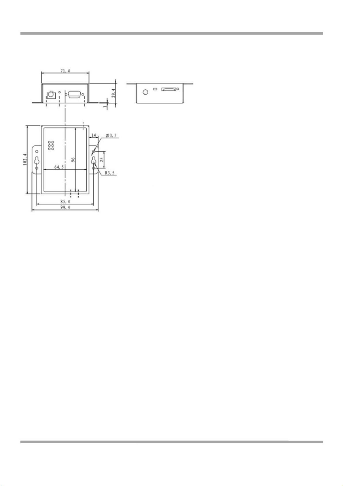
Dimension
Without ears (L x W x H): 102.4 x 71.4 x 29.4 mm
With ears (L x W x H): 102.4 x 99.4 x 29.4 mm
Characteristics
Installation Method
35mm Din-Rail or wall mounting or desktop
Operating Temperature
-25 to 70°C
Storage Temperature
-40 to 85°C
Environmental
Limits
Operating Humidity
5 to 95% RH
Directives
RoHS and WEEE compliant
Regulatory and
Type Approvals
CE and R&TTE Approval
CE 1177
Warranty
Warranty Period
1 year
Indunium 2i User Guide
11 / 77
)*>(?3@&093,09(
)*A(<&B&/%3,0(#0-(1'-&'307(?#%#(
Please refer to corresponding Indunium 2i datasheet.

Indunium 2i User Guide
12 / 77
!"#$%&'(5* (C09%#BB#%3,0(
5*)(12&'23&4(
5*5(8D?(C0-3/#%,'9(
Name
Color
Function
RSSI (3 LEDs)
Green
Cellular signal strength level
NET
Red
Please refer to
Table ME Functions
SYS
Green
Indicating the working mode.
Normal: blinking 2 times/second
Config: blinking 1 time/2 seconds
PWR
Green
On when DC power connection
RSSI LEDs
Function
None
No signal or SIM card not installed properly
1 bar
Weak or insufficient signal (SMS only)
2 bars
Average signal (GSM/CSD and GPRS connections)
3 bars
Exceptional signal (GSM/CSD and GPRS connections)

Indunium 2i User Guide
13 / 77
ME Functions
NET LED
Function
Off
ME is in one of the following modes:
-POWER DOWN mode
-ALARM mode
-CHARGE ONLY mode
-NON-CYCLIC SLEEP mode
-CYCLIC SLEEP mode with no temporary wake-up event in progress
600 ms on / 600ms
off
Limited Network Service: No SIM card inserted or no PIN entered, or network
search in progress, or ongoing user authentication, or network login in progress.
75 ms on / 3 s off
IDLE mode: The mobile is registered to the GSM network (monitoring control
channels and user interactions). No call is in progress.
75 ms on / 75 ms off
/
75 ms on / 3 s off
One or more GPRS PDP contexts activated.
500 ms on / 25 ms
off
Packet switched data transfer is in progress.
On
Depending on type of call:
Voice call: Connected to remote party.
Data call: Connected to remote party or exchange of parameters while setting up or
disconnecting a call.
5*:(E,.0%307(%"&(E,-&@(
Use 2 pcs of M3 screw to mount the modem on the wall.
Or to mount the modem on a DIN rail, you need DIN rail mount adapter.

Indunium 2i User Guide
14 / 77
5*>(C09%#BB#%3,0(%"&(<CE(!#'-(
Be sure to insert a SIM card before you use the modem.
Note: A SIM card set with PIN code cannot be used normally in the modem. You need to use Modem
Configurator to unlock the PIN code of the SIM card before using it in the modem.
Make sure to disconnect the charger and switch off your modem before inserting or removing your
SIM/USIM card.
Inserting SIM Card
1. Make sure your charger is disconnected.
2. Use a ball pen or paper clip to press the SIM holder eject button. The SIM holder will come out a little.
Then take out the SIM holder.
3. Insert the SIM card, with the metal surface facing downward, make sure it has completely sit on the
tray. Put the tray back into the slot, until you hear “a cracking sound”.
Removing SIM card
1. Make sure your charger is disconnected, and then press and hold down the power key until the
modem
is powered off.
2. Press the SIM card until you hear “a cracking sound”, when the SIM card will pop up to be pulled out.
Note:
1.
Don’t pull out the SIM holder without pushing the eject button.
2.
Don’t touch the metal surface of the SIM card in case information in the card is lost or destroyed.
3.
Don’t bend or scratch your SIM card. Keep the card away from electricity and magnetism.
4.
Make sure to disconnect the power source from your modem before inserting and removing your SIM
card.
5*A(!,00&/%(%"&(DF%&'0#B(G0%&00#(H<EG(IJ$&K(
Connect this to an external antenna with SMA male connector. Make sure the antenna is for the correct
frequency as your GSM operator with impedance of 50ohm, and also connector is secured tightly.

Indunium 2i User Guide
15 / 77
5*L(!,00&/%(%"&(E,-&@(%,(DF%&'0#B(?&23/&(
User can use the serial cable to connect the modem’s DB9 female connector to external controller /
computer.
PIN assignment for modem’s DB9 female connector
5*M(!,00&/%307(%"&(CN1(?&23/&(#0-(<&09,'9(
Digital Input Dry Contact:
PIN Assignment
DB9 Female Connector
PIN
RS232
RS485
(2-wire)
I/O
1
Data-(B)
2
RXD ->
Data+ (A)
3
TXD <-
4
DO
5
GND
GND
6
DI
7
RTS <-
8
CTS ->
9
IO
GND

Indunium 2i User Guide
16 / 77
Digital Output (Sink Type)
5*O( P',.0-307(%"&(E,-&@(
Grounding and wire routing help limit the effects of noise due to electromagnetic interference (EMI). Run the
ground connection from the ground screw to the grounding surface prior to connecting devices.
Note: This product is intended to be mounted to a well-grounded mounting surface, such as a metal panel.
5*Q(+,4&'(<.$$BJ(
The power supply range is 9 to 36VDC.
Note: Please take care about the polarity, and do not make reverse connection.

Indunium 2i User Guide
17 / 77
!"#$%&'(:* (1$&'#%&(%"&(E,-&@(
:*)(R,'6307(E,-&(12&'23&4(
There are two working modes available in the modem, please read carefully operate the Modem
Configurator software:
Mode
Description
Config Mode
When DIP switches to Config Mode, user could use follow functions:
1. Configure modem via Modem Configurator;
2. SMS Direct;
3. Auto-reboot;
4. Upgrade firmware.
Serial port default parameters: 115200, 8, None, 1
Normal Mode
When DIP switches to Normal Mode, user could use follow functions:
1. Control modem via AT commands;
2. Send/receive SMS via AT commands;
3. CSD communications;
4. GPRS communications;
5. Auto-reboot.
Serial port default parameters: Autobauding
The autobauding mode allows the modem to automatically detect the
transmission speed used by the DTE.
Only the following speeds will be detected: 300, 600, 1200, 2400, 4800,
9600, 14400, 19200, 28800, 38400, 57600, 115200bps. Auto-baud
detection cannot be guaranteed for speeds below or above these speeds.
:*5(E,-&@(!,0=37.'#%,'(12&'23&4(
Indunium-R Modem Configurator is a PC-based configuration software tool for managing and
configuring Induo Indunium 2i modems. With a full graphics mode and Windows-based environment, even
first time users will find it easy to learn how to use this new software tool. Indunium-R Modem
Configurator can be used to configure the general phone settings and modes, but without needing to look
up the appropriate AT commands. Indunium-R Modem Configurator provides a big improvement over the
traditional configuration method that often required frequent checking of a thick AT command reference
manual.
Indunium-R Modem Configurator not only makes configuration easier, but also makes it convenient to carry
out “mass deployment” and “pre-configuration,” but without the need to use AT commands. The most

Indunium 2i User Guide
18 / 77
important benefits of using the “Modem Configurator” utility are:
1. Green software, no need installation;
2. Full graphics mode, easy to learn how to configure the Indunium 2i modems;
3. The configuration profile can be easily stored, and then replicated to other modems;
4. Easy to upgrade modem firmware.
Note: Indunium-R Modem Configurator can be used with Windows 2000/XP/Vista/7 32/64-bit operation
systems.
:*5*) <%#'%307(E,-&@(!,0=37.'#%,'(
1. Switch the modem to “Config Mode”, connect the RS-232 port of the modem to a host PC and power

Indunium 2i User Guide
19 / 77
up the modem.
2. Double click “Modem Configurator.exe”to start the software.
3. Select the correct serial port that is connected to the modem, then click button.
After that you can see the popup window “Operation Succeed”.
Note: The RS-232 connector uses the standard PINOUT. A direct male DB9 to female DB9 cable can be
used to connect to a PC’s serial port. If you use a USB-to-serial product to configure the modem may
cause unexpected errors when configuring the modem.
Table of contents
Popular Modem manuals by other brands


Aztech
Aztech DSL605E Easy start guide

Sony Ericsson
Sony Ericsson GC75 user guide

PTI security systems
PTI security systems P485MODEMASY Installation and troubleshooting

MultiModem
MultiModem MT5634ZBA quick start guide

ADTRAN
ADTRAN 3G CDMA NIM Configuration guide

Advantek Networks
Advantek Networks AEM-56K-LU Quick installation guide


