Vitech VT5000ES48 User manual

VT5000ES48Lithium Battery
Product Manual
ViTech Power Systems
5/364 Park Road, Regents Park, NSW 2143
1300 699 669
www.vitechpower.com.au
Version:1.1 (22/09/2020)

Website: www.vitechpower.com.au
2
CONTENT
1. INTRODUCTION ..................................................................................................... 3
1.1. MAIN FEATURES ............................................................................................................................. 3
1.2. SAFETY PRECAUTIONS .................................................................................................................... 3
1.3. PRECAUTIONS FOR USE .................................................................................................................. 7
2. SPECIFICATION AND FUNCTIONS ...................................................................... 8
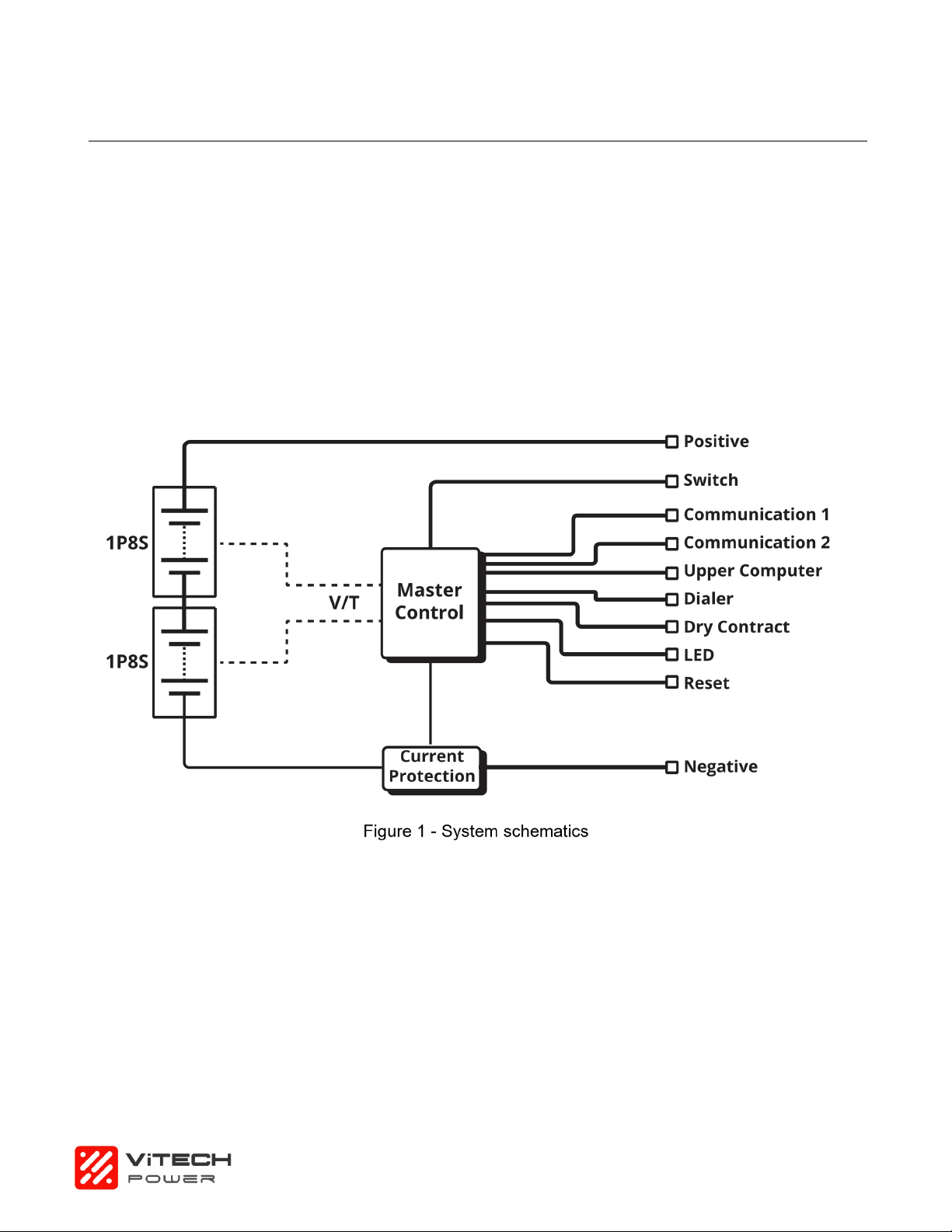
2.1. SYSTEM INTRODUCTION .................................................................................................................. 8
2.2. DIMENSIONS ................................................................................................................................... 9
2.3. SPECIFICATIONS ............................................................................................................................. 9
2.4. INSTALLING INSTRUCTIONS ............................................................................................................ 10
2.4.1. Definition of Voltage Sampling Connector .......................................................................... 10
2.4.2. Definition of Temp. Sampling Connector ............................................................................ 11
2.4.3. Front View ........................................................................................................................... 11
2.4.4 Port RS485 and RS232 ........................................................................................................ 12
3. INSTALLATION .................................................................................................... 13
3.1. DC CABLE REQUIREMENTS ........................................................................................................... 13
3.2. DC CABLE ................................................................................................................................... 13
3.2.1 Material List .......................................................................................................................... 13
3.2.2 Steps .................................................................................................................................... 13
3.3. DC CABLE CONNECTION ............................................................................................................... 14
3.3.1 Single Unit ............................................................................................................................ 14
3.3.2 Multi-Units in Parallel (4 sets as an example) ...................................................................... 15
3.3.3. Method to set up Master Pack and Slave Pack .................................................................. 16
4. POWER ON AND OFF .......................................................................................... 17
4.1. INSTRUCTION ............................................................................................................................... 17
4.1.1 System Power ON ................................................................................................................ 17
4.1.2. System Power OFF ............................................................................................................. 17
4.1.3. Sleep and Wake-up Function .............................................................................................. 17
4.1.4. Buzzer Function .................................................................................................................. 17
4.1.5. System Status Instruction ................................................................................................... 17
4.1.7. SoC Indicator ...................................................................................................................... 18
5. TRANSPORTATION AND STORAGE ................................................................. 19
5.1. TRANSPORTATION ........................................................................................................................ 19
5.2. STORAGE ..................................................................................................................................... 19
6. DISCLAIMER ........................................................................................................ 19

3
1. Introduction
Thank you for choosing ViTech Power energy storage system.
The energy storage module comprises of lithium ion rechargeable batteries with 5.12 kWh capacity, and
the controller enables a central of multiple modules.
This manual provides information regarding safety precautions to prevent possible accidents and how
to use the product.
Please read this manual carefully before use for safety and keep this manual handy for reference.
1.1. Main Features
Some main features of this product are:
nLong Life Span
The battery can be expected to remain serviceable for more than 10 years, considering that it is charged
and discharged once in a day at room temperature (25 °C).
nLong Life Span
Olivine-type lithium iron phosphate batteries with excellent thermal stability and storage characteristics
are used in this product. The module also incorporates a self-monitoring function for the detection of any
abnormalities in energy storage.
nCompact Design
The height is nicely designed in 3U, in favor of standard industrial applications.
nHigh Scalability
Multiple energy storage modules can be connected in parallel, and the capacity can be customized
according to the intended use.
1.2. Safety Precautions
ViTech Power products are designed with full consideration of safety. However, all electrical
appliances can be dangerous if used inappropriately; it can cause a fire or electric shock that leads to
severe injury or death. For your protection, please read these safety precautions thoroughly.
Definitions of Symbols:
Below are symbols used in this manual and the unit.
Please read through the following definitions before reading the manual.
Warning
If you ignore these instructions, it can lead to a fire or electric shock
causing serious injury or death.
Caution
If you ignore these instructions, it can lead to electric shock or other
accidents causing injury or harm to nearby products.
Website: www.vitechpower.com.au

4
nInstruction
Use designated cable. A non-designated cable use can cause electric shock. Be sure to use the cable
designated in this manual.
nProhibited
Do not damage cables. If you damage a cable, it can cause a fire or electric shock.
1. Do not work over or damage a cable.
2. Do not place heavy objects on a cable or pull the cable.
3. Do not place a heater near the cable, which may result in the cable overheating.
4. Do not tuck down a cable when installing in a rack.
5. When you unplug a communication cable, be sure to hold the plug and pull it.
nInstruction
Connect a power cable and communication cable properly.
1. If you connect a power cable improperly, contact resistance will increase and it may damage the parts
or cause a fire.
2. Insert the connector of the communication cable all the way in. If it is connected improperly, the system
may be deactivated.
nProhibited
Do not install in a closed area. If the module/controller is installed in a closed area with no air-conditioning,
heat may build up inside the set and cause a fire.
nProhibited
Do not place the set in direct sunlight or near a heater. Doing so can cause deformation, a breakdown,
or a fire. Pay extra attention when you place the set near windows.
nProhibited
Do not install the set where excessive oil smoke, steam, moisture or dust is contained in the air. If the set
is installed in such a place, it may cause a fire or electric shock.
nInstruction
1. Wear insulating gloves and protection glasses during installation and connection
If you do not follow the instructions below, it can lead to a fire or electric shock causing
serious injury or death.
Warning
Website: www.vitechpower.com.au

5
2. Wear insulating gloves and protection glasses during installation and connection of the set to prevent
electric shock or other injuries.
nNo Wet
1. Do not allow water and/or foreign objects inside the module
2. Water or foreign objects inside the module can cause a fire or electric shock.
3. Should this occur, however, turn off the “POWER ON/OFF” switch on the controller to shut down, and
remove the power connector from the POWER CONNECTOR terminal of the module.
nDo not disassemble
Do not open the set unnecessarily. Opening and modifying the set can cause a fire or electric shock.
nProhibited
Do not cover the vent. If the vent is covered, heat may build up inside the set and cause a fire.
1. Do not put the set in a poorly ventilated and narrow space.
2. Remove any dust buildup in the vent.
3. Do not place the set upside down or sideways.
4. Do not place on a shag carpet or bed.
5. Do not cover the vent with a cloth, etc.
nInstruction
Install in a stable place.
1. If you install the set in an unstable place, such as an unstable rack, it may fall and cause injury.
2. Do not install upside down or sideways. The set may drop and cause injury.
nInstruction
Use the designated packaging materials for transportation. If you do not use the designated packaging
materials, the packaging material may be damaged by vibration during transportation and it may cause
injury.
nInstruction
Install based on the designated way of installation. If you do not follow the designated way of installation,
the set may drop due to the strength poverty and can cause injury.
nInstruction
If you ignore any of the following instructions, it can cause injury or damage to nearby
products.
Caution
Website: www.vitechpower.com.au

6
Fix a rack to the floor. If a rack falls by the weight of the set, it may cause serious injury or death.
nNo Wet
Do not touch with wet hands If you touch the set with wet hands, it may cause electric shock.
nInstruction
Install other equipment or accessories properly. If you inadequately install other equipment or accessories
sold separately, they may fall and cause injury. When you install any of the following accessories, install
it properly based on this manual.
nInstruction
Set up cables properly If your foot is caught by a cable, the set may fall and cause injury. Connect and
install cables carefully.
nInstruction
Power off at a malfunction In case any malfunction happens, please turn off the POWER ON/OFF switch
in order to shut down, and remove the power connector from the POWER CONNECTOR terminal of the
module.
nProhibited
Do not put anything, stand or sit on the set If you put anything on the set, it may fall and cause injury.
Also, if it is used as a stool, for example, it may topple and cause injury.
nInstruction
Follow related laws or ordinances for disposal. When you dispose of this product, do not dispose as
general or household waste.
nInstruction
Disposal with specified method Contact technical vendor when you discard. Do not disassemble, destroy,
or disposal in the fire.
Do not allow the liquid to come in contact with skin or clothing.
nIf the liquid comes in contact with skin or clothing, wash thoroughly with plenty of water.
nIf the liquid gets into the eyes or mouth, flush immediately with clean water, and immediately seek
medical treatment.
nContact customer service.
If liquid is leaking from the module, observe the following measures.
Danger
Website: www.vitechpower.com.au

7
1.3. Precautions for Use
nIn the case of a failure, or any of the abnormalities shown below, turn off the set and contact ViTech
Power customer services.
1. Abnormal sound, smell or smoke.
2. Water or particles inside the product.
3. The product is dropped, or the cabinet is damaged.
nCharge and discharge the product according to the control signals of the controller. Do not hammer a
nail or punch a hole in the product.
nReplace the module with a new one if discharge time at room temperature is noticeably short, even
from fully charged.
DO NOT:
nDisassemble.
nModify the product (Modification may destroy the protection function inside, or cause abnormal
charge/ discharge, heat generation, gas eruption, or fire.).
nTouch the rear output terminal except for installation.
nThrow the product into fire or heat, or otherwise expose the set to heat or naked flame.
nSubmerge the product in liquid or allow it to become wet.
nApply strong shock, crush, or drop.
nUse for medical purposes.
nPlace any foreign objects inside.
nConnect any devices that exceed the operating voltage and current range.
nDo not unplug the power connector from the POWER CONNECTOR terminal while power is turned
on.
Website: www.vitechpower.com.au

8
2. Specification and Functions
2.1. System Introduction
VT5000ES48 Energy Storage System is consisted of 2 sets of 1P8S lithium cell modules. In each 1P8S
lithium cell module, there are 8 pcs of 100 Ah LFP cell. The overall system also provides standard
communication port, i.e. CAN and RS485, to monitor the working status and communicate with
upper machine as well as the Power Conversion System (PCS) in front. The system schematic drawing
is presented in Figure 1.
Website: www.vitechpower.com.au

9
2.2. Dimensions
VT5000ES48 dimensions are presented in Figure 2. It is well designed for 19 inch cabinet.
Figure 2 - VT5000ES48 Dimension
2.3. Specifications
Specifications of VT5000ES48
Cell Type
LiFePO4 (LFP)
Rated Voltage (V)
51.2
Rated Capacity (Ah)
100
Rated Energy (kWh)
5.12
Packing
1P16S
Working Voltage Range (V)
44.8~57.6
Standard Charging Current (A)
50
Max. Continuous Charging Current (A)
50
Standard Discharging Current (A)
50
Standard Charging Method
0.5C CC to 57.6V; CV at 57.6V till current is 0.05C
Working Temp. (°C)
Charging: 0 ~50; Discharging: -20~55
Working ROH
20%~80%
Storage Temp. (°C)
-20~50
Website: www.vitechpower.com.au

10
Self-discharging rate
≤5% (25 °C, 50% SoC)
SoC @ end of product line
40%
Insulation Resistance (MΩ)
>100
Voltage Difference in each module (mV)
≤20
Inner Resistance of single Cell (mΩ)
0.34±0.05
(fresh cell 30~40% SoC)
Weight (kg)
Approx. 48
Dimension (mm)
440*530*132
(not include connector, MSD and other parts)
2.4. Installing Instructions
Some instructions for installing the equipment must be followed. (Refer to our Energineer)
2.4.1. Definition of Voltage Sampling Connector
PIN
Wire No.
Signal
Wire size (mm²)
Remarks
1
B0
Signal
0.3
Cell #1-
2
B2+
Signal
0.3
Cell #2+
3
B4+
Signal
0.3
Cell #4+
4
B6+
Signal
0.3
Cell #6+
5
B8+
Signal
0.3
Cell #8+
6
B10+
Signal
0.3
Cell #10+
7
B12+
Signal
0.3
Cell #12+
8
B14+
Signal
0.3
Cell #14+
9
B16+
Signal
0.3
Cell #16+
10
NC
NC
NC
NC
11
B1+
Signal
0.3
Cell #1+
12
B3+
Signal
0.3
Cell #3+
13
B5+
Signal
0.3
Cell #5+
14
B7+
Signal
0.3
Cell #7+
15
B9+
Signal
0.3
Cell #9+
16
B11+
Signal
0.3
Cell #11+
17
B13+
Signal
0.3
Cell #13+
18
B15+
Signal
0.3
Cell #15+
Website: www.vitechpower.com.au

11
2.4.2. Definition of Temp. Sampling Connector
PIN
Wire No.
Signal
Wire size (mm²)
Remarks
1
T1+
Signal
0.3
Temp. #1+
2
T2+
Signal
0.3
Temp. #2+
3
T3+
Signal
0.3
Temp. #3+
4
T4+
Signal
0.3
Temp. #4+
5
T1-
Signal
0.3
Temp. #1-
6
T2-
Signal
0.3
Temp. #2-
7
T3-
Signal
0.3
Temp. #3-
8
T4-
Signal
0.3
Temp. #4-
2.4.3. Front View
Figure 3 - Front View of VT5000ES48
Item
Name
Model
Remarks
1
SOC LED x4
2
Alarm LED
3
RUN LED
4
Dialer
5
Communication port
RJ11
RS232 To upper machine
6
Communication port *2
RJ45
CAN To PCS RS485 Internal Connection
7
Reset
Waken system from malfunction status
8
Dry Contact
9
Power On/Off Switch
10
Port Negative x2
PSR6XAB
Black 5.7, 25 mm2
11
Port Positive x2
PSR6XBB
Orange 5.7, 25mm2
12
GND
M6
Yellow-Green, 10 AWG
Website: www.vitechpower.com.au

12
2.4.4 Port RS485 and RS232
Figure 4 - CAN/RS485 and RS232 connections
Description
CAN
Pin 1: CAN-H
Pin 5: CAN-L
Pin 2, 3, 4, 6, 7: NC
Pin 8: GND
RS485
Pin 1, 4, 5: NC
Pin 2, 7: RS485-A
Pin 3, 6: RS485-B
Pin 8: GND
RS232
Pin 1, 2, 6: NC
Pin 3: BMS transmit; Computer receiver
Pin 4: BMS receiver; Computer transmit
Pin 5: GND
Website: www.vitechpower.com.au

13
3. Installation
3.1. DC Cable Requirements
Size
Outer Diameter
Max. Voltage
Max. Current
21-33 mm²
10-12 mm
1000 V
120 A
3.2. DC Cable
3.2.1 Material List
Plug Isolation Cap Tail-hood
3.2.2 Steps
1. Put wire through isolation cap and Tail-Hood.
2. Swipe outer isolation layer of DC cable.
DC cable must be a
multicore wire.
Caution
n
Turn off system before doing electrical connection
n
Ensure all the cables are in electrical safe condition
Danger
Website: www.vitechpower.com.au

14
3. The red is used for the positive, and the black is for
negative
The end of the cable is
bunched at the terminal using a wire clamp.
4. Tighten the isolation cap and plug contact.
5. Put the positive and negative plug on to the system and tighten it.
6. Use isolation cap for unused DC plug.
3.3. DC Cable Connection
3.3.1 Single Unit
Figure 5 - Single Unit Connection
Website: www.vitechpower.com.au

15
3.3.2 Multi-Units in Parallel (4 sets as an example)
Figure 6 - Multi-Units Connection
Master Pack and Slave Pack VT5000ES48 can be used as single unit as well as multi-units (in
parallel) mode. The customer must inform supplier if multi-units mode is required. The Master
Pack can be used individually, but Slave Pack cannot be used individually.
Website: www.vitechpower.com.au

16
3.3.3. Method to set up Master Pack and Slave Pack
Figure 7 - Dial Diagram
Master/Slave machine dial code diagram:
Website: www.vitechpower.com.au

17
4. Power ON and OFF
4.1. Instruction
Please double check the Precautions for use in section 1.3.
4.1.1 System Power ON
nInstallation (including DC cable, communication wire connection and dialer switch) is properly done.
nPress Power Switch button, green LED should be twinkling and then turn into function mode. (system
status can be red from LED signal, as shown below)
4.1.2. System Power OFF
Attention: It must be confirmed that the system is off before taking off DC cables.
Press Power Switch button
Green LED should be twinkling and then turn into stop mode
4.1.3. Sleep and Wake-up Function
Number
Sleep Condition
Wake-up Condition
Mark
1
Forced sleep by upper computer
Reset button
2
Forced sleep by soft switch
Soft switch
Only those equipped with
soft switch can pass the
call Wake up
3
Total Voltage is lower than 48V
or monomer is lower than 2.8V,
and continuous No charge and
discharge current for 4 hours,
no communication goes to
sleep
Reset button
Soft switch
Communication
Charging
Only those equipped with
soft switch can pass the
call Wake up
4.1.4. Buzzer Function
n0.25s per 1s in case of fault
n0.25s per 2s during protection
4.1.5. System Status Instruction
There are 6 LED indicator, 4 green LED gives status of SoC, 1 red Alarm LED and 1 green Running
Status LED (indicating charging, discharging etc.)
Website: www.vitechpower.com.au

18
Status
Normal/Warning/Protection
RUN
ALM
SoC
Remarks
Power Off
Hibernate
no
no
no
no
no
no
Standby
Normal
Twinkle 1
no
Real SoC
Warning
Twinkle 1
no
Temp. Warning ALM
Twinkle 3
Charging
Normal
Twinkle 2
no
Real SoC
/
Warning
Twinkle 2
no
Temp. Warning ALM
Twinkle 3
Overcharging
Twinkle 1
no
Overcharging, ALM no
Overheat, Low Temp., Over-
current
Twinkle 1
Twinkle 2
Discharging
Normal
Continuous
no
Real SoC
Warning
Continuous
Twinkle 3
Overcharging, ALM no
Over-discharging
Twinkle 1
no
Overheat, Low Temp., Over-
current, Shortcut
Twinkle 1
Twinkle 2
Malfunction
Warning
no
Continuous
no
no
no
no
BMS Damage, MOS
Damage, Temp.
sampling malfunction
4.1.6. LED Twinkle Status
Status
On
Off
Twinkle 1
0.25s
3.75s
Twinkle 2
0.5s
0.5s
Twinkle 3
0.5s
1.5s
4.1.7. SoC Indicator
SoC
LED
LED1
LED2
LED3
LED4
0~25%
On
OFF
OFF
OFF
25%~50%
On
On
OFF
OFF
50%~75%
On
On
On
OFF
75%~100%
On
On
On
On
Website: www.vitechpower.com.au

19
5. Transportation and Storage
5.1. Transportation
It is forbidden to encounter serious vibration and shock during transportation.
5.2. Storage
If the system is not placed to use, the system must be properly stored. Otherwise, if any issues, ViTech
Power shall not be liable.
nIt should be stored in 60% SoC status.
nIt should be stored at ventilation environment, Temp. < 35 °C, ROH <65%.
nIt should be stored avoiding humid condition.
nIt should be stored in place where they can be monitored by professionals.
6. Disclaimer
It should be noted that ViTech Power shall not be liable if any necessary materials are added to this
user’s manual without further inform of customers.
Website: www.vitechpower.com.au

20
Website: www.vitechpower.com.au
ViTech Power Systems
5/364 Park Road, Regents Park, NSW 2143
1300 699 669
www.vitechpower.com.au
Version:1.1 (22/09/2020)
Table of contents