manuals.online logo
Brands
  1. Home
  2. •
  3. Brands
  4. •
  5. VITECTOR FRABA
  6. •
  7. Camera Accessories
  8. •
  9. VITECTOR FRABA OSE-C1003 User manual

VITECTOR FRABA OSE-C1003 User manual

O S E - C 1 0 0 3 I N S T A L L A T I O N M A N U A L
Release Date: 21-Nov-11 VITECTOR Page 1/4
I M P O R T A N T S A F E T Y I N S T R U C T I O N
TO REDUCE THE RISK OF INJURY OR DEATH TO PERSONS
1. READ AND FOLLOW ALL INSTRUCTIONS
2. Disconnect power supply before attempting installation
3. For use with OPTOEDGE or OPTOTEYE entrapment protection devices
4. OPTOEYE photo eyes are to be placed at the bottom of the opening no
more than 6 inches (doors)/ 27.5 inches (gates) from the ground
5. OPTOEDGE safety edges are to be placed where risk of entrapment or
obstruction exists, such as the bottom edge of a vertically closing edge
6. Ensure door or gate opening is clear before testing the unit
7. SAVE THESE INSTRUCTIONS FOR FUTURE REFERENCE
Overview
The OSE-C 1003 converter box is used to connect
up to two sensing devices on a relay style
operator. The converter box is able to convert the
dynamic signal of the optical sensors to a NO dry
contact relay output that can be connected to a
relay style operator.
Technical Data
OSE-C 1003
Supply Voltage
12 / 24 V AC / DC
Relay Rating
Max switched current
1A @ 30V AC/DC
Operating
Temperature
-13 °F to +130 °F
Dimensions
3.88 in x 2.41 in x 1.17
in
Connection Table
OSE-C 1003
Black
12 / 24 V AC Input
Gray
Normally Open Edge Contact
(Entrapment Terminal)
Red
Primary Device Input
Orange
Secondary Device Input (optional)
Yellow
Close Door Button (optional)
O S E - C 1 0 0 3 I N S T A L L A T I O N M A N U A L
Release Date: 21-Nov-11 VITECTOR Page 2/4
Installation
1. Disconnect the operator from power source.
2. Open the operator box faceplate.
3. Using the wire nuts provided, connect the OSE-
C 1003 to entrapment protection devices:
IF ONE EXTERNAL DEVICE IS USED:
Connect device to the RED wires of the OSE-C
1003.
IF TWO EXTERNAL DEVICES ARE USED:
Connect the primary sensing device to the RED
wires and the secondary device to the
ORANGE wires.
4. Connect the gray wires to the NO entrapment
protection device (reverse) terminals of the
operator.
5. For connection of YELLOW wires follow the
procedure in the “Constant Pressure to Close
Feature” section (page 3)
6. Connect the black wires to 24VAC
BE SURE TO CONNECT TO 24VAC AND
NOT PHASE POWER
DO NOT USE 24V SUPPLIED TO
EXTERNAL RADIO CONTROL
7. Securely fasten the OSE-C to the inside of the
door lift casing where convenient.
8. Close box faceplate
9. Reconnect power
10. Test all door lift functions and sensing devices
by following the testing procedure as
described below.
OPTOEYE OR OPTOEDGE
O S E - C 1 0 0 3 I N S T A L L A T I O N M A N U A L
Release Date: 21-Nov-11 VITECTOR Page 3/4
Testing and Troubleshooting
1. Ensure opening is clear and safe before
testing
2. Run operator to mid-travel position and stop.
Start operator close, the operator should close
normally. If not, disconnect power and recheck
all connections
3. From mid-travel position start operator close
then activate one of the external devices. The
operator should stop and reverse direction.
4. If OSE-C 1003 does not function as stated
above. Reset the device as noted in RESET
PROCEDURE and then recheck all
connections, including that of external
devices.
Constant Pressure to Close Feature
For some type/brands of operators, the OSE-C
1003 can monitor the close push button and allow
for a constant contact to close if the OSE-C 1003
detects an obstruction or there is a fault with one of
the sensing devices. Typically, this feature will not
work with instant reversing or 3-phase motors
This is an optional feature and the OSE-C 1003
will work without Push-Button Sensing. However, if
an external device becomes disabled, manual
operation may be required to close door or gate.
1. Disconnect Power from operator
2. Connect YELLOW wires to close button
(as shown in CONENCTION DIAGRAM)
3. To test, disable one of the external
devices at mid-travel, the door should
close if the close button is held down.
Reset Procedure
Once the OSE-C 1003 detects a sensing device, it
saves this status to permanent memory. When
power is removed and reapplied, the OSE-C 1003
expects the device to be present. If not, it will
activate the reversing signal. To reset the
controller:
1. Disconnect power
2. Disconnect any sensing edge and one of the
gray wires from the operator
3. Remove the back of the OSE-C 1003 and
locate the shunt jumper on the printed circuit
board
4. Move the shunt jumper to the reset position
5. Apply power to the controller for 2 seconds
with the shunt jumper in the reset position
6. Disconnect power from the unit and move the
shunt jumper back to the original position
7. Reconnect the gray wire (removed above) to
the operator
8. Reconnect the sensing device(s)
9. Reconnect power to retest and resume
operation.
O S E - C 1 0 0 3 I N S T A L L A T I O N M A N U A L
Release Date: 21-Nov-11 VITECTOR Page 4/4
Connection Diagram

Popular Camera Accessories manuals by other brands

Brinno Pan Lapse quick start guide

Brinno

Brinno Pan Lapse quick start guide

Sun Fun Kits SFK-260 user manual

Sun Fun Kits

Sun Fun Kits SFK-260 user manual

FreeVision Vilta user manual

FreeVision

FreeVision Vilta user manual

Aura 91919-PG manual

Aura

Aura 91919-PG manual

ResMed Astral user guide

ResMed

ResMed Astral user guide

Stryten Energy M Series Installation and operating instructions

Stryten Energy

Stryten Energy M Series Installation and operating instructions

Aegis ABL-24060P user manual

Aegis

Aegis ABL-24060P user manual

Canon Easydive Leo3 quick start guide

Canon

Canon Easydive Leo3 quick start guide

Videotec OUPT5CPU instruction manual

Videotec

Videotec OUPT5CPU instruction manual

Husqvarna 100-B380X Operator's manual

Husqvarna

Husqvarna 100-B380X Operator's manual

PROAIM P-MN-TS instruction manual

PROAIM

PROAIM P-MN-TS instruction manual

LINHOF SUPER TECHNIKR operating manual

LINHOF

LINHOF SUPER TECHNIKR operating manual

Smith-Victor LED Desktop Studio Assembly instructions

Smith-Victor

Smith-Victor LED Desktop Studio Assembly instructions

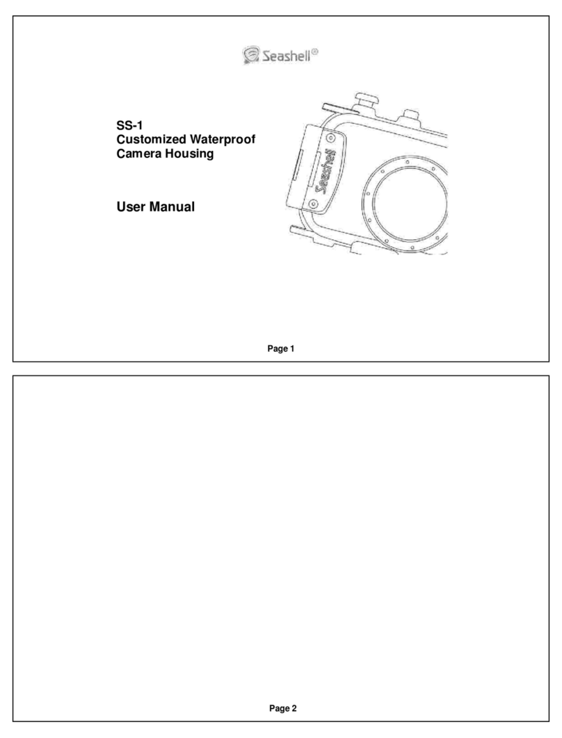
Seashell SS-1 user manual

Seashell

Seashell SS-1 user manual

Miller Electric Camera Accessories user manual

Miller Electric

Miller Electric Camera Accessories user manual

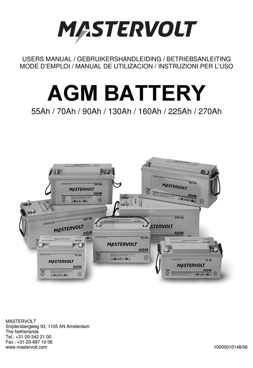
Mastervolt AGM 55Ah user manual

Mastervolt

Mastervolt AGM 55Ah user manual

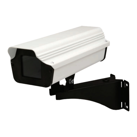
Moog Videolarm ACH13 Installation and operation instructions

Moog Videolarm

Moog Videolarm ACH13 Installation and operation instructions

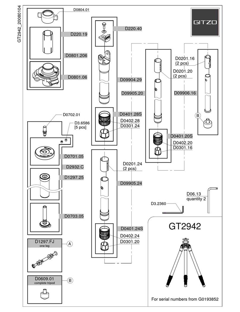
Gitzo GT2942 parts list

Gitzo

Gitzo GT2942 parts list

manuals.online logo
manuals.online logoBrands
  • About & Mission
  • Contact us
  • Privacy Policy
  • Terms and Conditions

Copyright 2025 Manuals.Online. All Rights Reserved.