Vivace HART VHC10-P Quick guide
INSTALLATION, OPERATION, CONFIGURATION AND MAINTENANCE MANUAL
February/2020
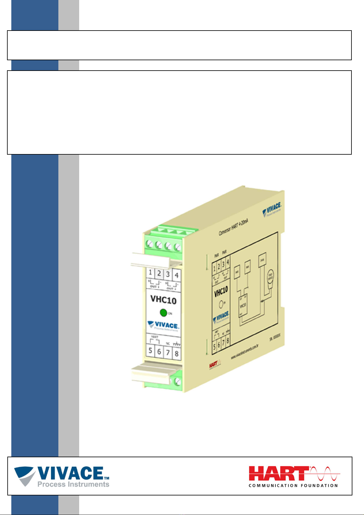
VHC10-P
HART® 4 – 20 mA CONVERTER
panel model

VHC10-P CONVERSOR HART
®
4 – 20 mA MAN AL DE INSTALAÇÃO, OPERAÇÃO, CONFIG RAÇÃO E MAN TENÇÃO
______________________________________________________________________________________________________________________________
COPYRIGHT
All rights reserved, including translations, reprints, complete or partial reproduction of this manual, patent
concession or model register of use/project.
No part of this publication may be reproduced, copied, processed or transmitted on any manner or any
medium (photocopy, scanning, etc.) without the express permission of Vivace Process Instruments Inc., not
even for training or electronic systems.
HART
®
is a registered mark from HART Communication Foundation.
NOTE
We have reviewed this manual with great care to maintain compliance with the hardware and software
versions described herein. However, due to the dynamic development and version upgrades, the possibility of
technical deviations cannot be ruled out. We cannot accept any responsibility for the full compliance of this
material.
Vivace reserves the right to, without notice, make modifications and improvements of any kind in its products
without incurring in any circumstances, the obligation to make those same modifications to products sold
previously.
The information in this manual is frequently updated. Therefore, when using a new product, please check the
latest version of the manual on the Internet through our website www.vivaceinstruments.com, where it can be
downloaded.
You customer is very important for us. We will always be grateful for any suggestions for improvements as well
as new ideas, which can be sent to the e-mail: contato@vivaceinstruments.com preferably with the title
"Suggestions".

VHC10-P CONVERSOR HART
®
4 – 20 mA MAN AL DE INSTALAÇÃO, OPERAÇÃO, CONFIG RAÇÃO E MAN TENÇÃO
______________________________________________________________________________________________________________________________
SUMMARY
1EQUIPMENT DESCRIPTION..................................................................................................................................5
1.1. BLOCK DIAGRAM.........................................................................................................................................5
2INSTALLATION ......................................................................................................................................................6
3CONFIGURATION ..................................................................................................................................................8
3.1. JUMPERS FOR LOCAL ADJUST AND WRITE PROTECTION ...................................................................8
3.2. HART
®
PROGRAMMER ................................................................................................................................8
3.3. CONFIGURATION PARAMETERS...............................................................................................................9
3.4. PROGRAMMING TREE FOR HART CONFIGURATOR ............................................................................10
3.5. SAFE OUTPUT............................................................................................................................................12
3.6. FDT/DTM CONFIGURATION......................................................................................................................12
4TECHNICAL CHARACTERISTICS ......................................................................................................................13
4.1. CASE DIMENSIONS ...................................................................................................................................13
4.2. IDENTIFICATION ........................................................................................................................................13
4.3. ORDERING CODE ......................................................................................................................................13
4.4. TECHNICAL AND PHYSICAL SPECIFICATIONS......................................................................................14
4.5. SPARE PARTS............................................................................................................................................14
5WARRANTY..........................................................................................................................................................15
5.1. GENERAL CONDITIONS ............................................................................................................................15
5.2. WARRANTY PERIOD .................................................................................................................................15
APPENDIX I – TECHNICAL ANALYSIS REQUEST ...................................................................................................16

VHC10-P CONVERSOR HART
®
4 – 20 mA MAN AL DE INSTALAÇÃO, OPERAÇÃO, CONFIG RAÇÃO E MAN TENÇÃO
______________________________________________________________________________________________________________________________
1
It is extremely important that all the safety instructions, installation and operation in this manual are followed
faithfully. The manufacturer is not liable for damage or malfunction caused by improper use of this equipment.
It is recommended to strictly following the rules and good practice relating to installation, ensuring correct
grounding, noise insulation and good quality cables and connections in order to provide the best performance
and durability to the equipment.
Special attention must be considered in relation to installations in hazardous areas, where applicable.
WARNING
•Appoint only skilled people, trained with process and equipment;
•Install equipment only in operation compatible areas, with the proper connections and protections;
•Use proper safety equipment for any handling device in field;
•Turn area power off before equipment installation.
SAFETY PROCEDURES
SYMBOLOGY
Caution - indicates risk or error source
Important Information
General or Specific Risk
Electric Shock Danger
GENERAL INFORMATION
Vivace Process Instruments ensures the operation of this equipment, according to the descriptions
contained in its manual, as well as technical characteristics, not guaranteeing its full performance
in particular applications.
The operator of this equipment is responsible for observing all aspects of safety and prevention of
accidents applicable during the execution of the tasks in this manual.
Failures that might occur in the system, causing damage to property or injury to persons, shall
additionally be prevented by external means to a safe outlet for the system.
This equipment must be used only for the purposes and methods proposed in this manual.

VHC10-P CONVERSOR HART
®
4 – 20 mA MAN AL DE INSTALAÇÃO, OPERAÇÃO, CONFIG RAÇÃO E MAN TENÇÃO
______________________________________________________________________________________________________________________________
1 EQUIPMENT DESCRIPTION
T
he HART
®
4-20 mA VHC10-P converter is a member of the Vivace Process Instruments product family, designed to
create up to two additional 4-20 mA current channels, aiding analog monitoring in devices that do not have this
feature (valve positioners, for example) or that need this monitoring in more than one variable.
The converter can be powered by voltages between 12 and 45 Vdc, generating up to two 4-20 mA current channels
(according to NAMUR NE43 standard). Its function is to monitor any user-configured variables of other HART
®
equipment (regardless of its version) and output them through the current channels.
Its configuration uses the HART
®
7 communication protocol, already established as the most used in the industrial
automation world for configuration, calibration, monitoring and diagnostics.
The converter configuration is carried out at the beginning of its operating cycle, with the converter in "slave" mode,
being completed by the user by changing the use mode to "master". Configurations can be performed using a
HART
®
configurator or tools based on EDDL
®
or FDT/DTM
®
.
Prioritizing high performance and robustness, it was designed with the latest technologies in electronic components
and materials, ensuring long-term reliability for systems of any scale.
1.1. BLOC DIAGRAM
The modularization of the converter components is described in the following block diagram.
Figure 1.1 –VHC10-P block diagram.
The DC source input block is responsible for powering all circuits. The current control block is composed of a circuit
that transforms the digital values generated by the microcontroller into 4-20 mA currents, proportional to the
variables monitored by the converter.
The HART
®
modem block interfaces the microcontroller signals with the HART
®
line connected to the monitored
equipment.
Finally, the CPU block can be related to the converter's brain, where all the time controls, switching between HART
®
Master/Slave state machines take place, in addition to routines common to transmitters, such as configuration,
calibration and generation of output values digital for the currents, proportional to the monitored variables.
VHC10-P CONVERSOR HART
®
4 – 20 mA MAN AL DE INSTALAÇÃO, OPERAÇÃO, CONFIG RAÇÃO E MAN TENÇÃO
______________________________________________________________________________________________________________________________
6
2 INSTALLATION
RECOM
M
ENDA
TION
When taking the equipment to the installation site, transfer it in the original packaging. Unpack the
equipment at the installation site to avoid damage during transportation.
RECOM
M
ENDA
TION
The equipment model and specifications are indicated on the identification labels located on the front
and side of the enclosure. Check that the specifications and model provided are as specified for your
application and requirements.
The electrical installation of the VHC10-P converter must be carried out after fixing it to the DIN rail. The HART
channel must be connected between the converter and the equipment to be monitored and, only later, connect the
supplies to the converter's current channels.
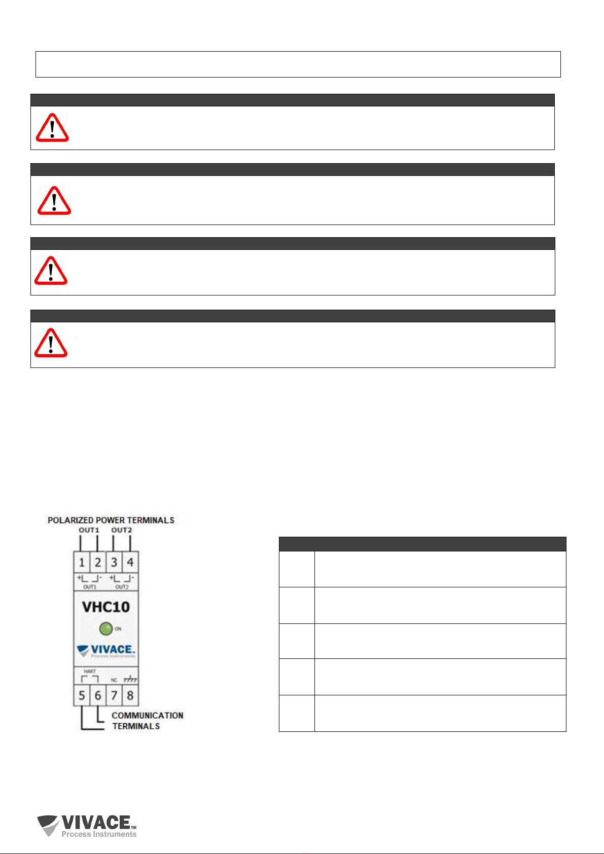
Converter connections are shown in figure 2.1 (2-channel model).
Note at the top, that the converter is powered by a voltage source (12 to 45 Vdc - OUT1) and its input is polarized,
with the positive terminal being number 1 (on the left) and the negative terminal being the number 2 (on the right).
Terminals 3 and 4 must be powered by another voltage source (polarized input) to enable the output of current
OUT2 for the two-channel model.
Figure 2.1 – Identification of converter terminals. Table 2.1 – VHC10-P terminal description.
NOT
E
All cables used to connect the VHC10-P to the HART
®
network must be shielded to avoid interference
and noise.
NOT
E
It is extremely important to ground the equipment for complete electromagnetic protection, in addition to
ensuring the correct performance of the converter on the HART
®
network.
Terminal Description
1 – 2 Terminals for Powering CHANNEL 1 - OUT1
12 to 45 Vcc polarized
3 – 4 Terminals for Powering CHANNEL 2 - OUT2
12 to 45 Vcc polarized
5 – 6 Terminals for Communication – HART
HART
®
communication with monitored device
7 Not connected terminal
8 Ground terminal

VHC10-P CONVERSOR HART
®
4 – 20 mA MAN AL DE INSTALAÇÃO, OPERAÇÃO, CONFIG RAÇÃO E MAN TENÇÃO
______________________________________________________________________________________________________________________________
7
At the bottom user can find the HART
®
communication terminals (terminals 5 and 6). In this case, there is no polarity.
Terminal 7 must be left open and terminal 8 can be optionally grounded.
The VHC10-P can monitor variables from HART
®
devices powered by voltage (transmitters) or by current (valve
positioners). The communication connections with these devices are represented, respectively, in figures 2.2 and
2.3, below.
In the case of monitoring a transmitter equipment (figure 1.4), a load of 250 ohms is required to enable the
modulation of the current in the HART
®
standard, in series with the transmitter's supply voltage.
User must use an independent voltage source to power the transmitter, different from the source(s) of the VHC10-P
converter, since the converter output currents will indicate the variables read from the transmitter, as indicated in the
figures.
Communication terminals 5 and 6 of the converter must be connected over the 250 ohm load, where there is
modulation of the HART
®
signal in the current.
Figure 2.2 – Connection between converter and transmitter Figure 2.3 – Connection between converter and valve
– 2-channel model. positioner.
In the case of monitoring a valve positioner (figure 2.3), a 250 ohm load is not required for communication, as the
valve positioner is powered by a 4-20 mA current input.
Note that in this example only one output is used to monitor the valve position by reading the positioner's PV
variable.
Communication terminals 5 and 6 of the converter must be connected directly to the current supply input of the
positioner.
INSTAL
L
A
TION
When mounting the equipment in panels or boxes in the field, make sure that the moisture seals are
adequate and ensure that the connections to the unused box entries are closed, as the ingress of
moisture can generate low insulation and damage the electronic circuits.
In wet conditions, damage caused to the equipment will NOT be covered by the warranty.
VHC10-P CONVERSOR HART
®
4 – 20 mA MAN AL DE INSTALAÇÃO, OPERAÇÃO, CONFIG RAÇÃO E MAN TENÇÃO
______________________________________________________________________________________________________________________________
8
3 CONFIGURATION
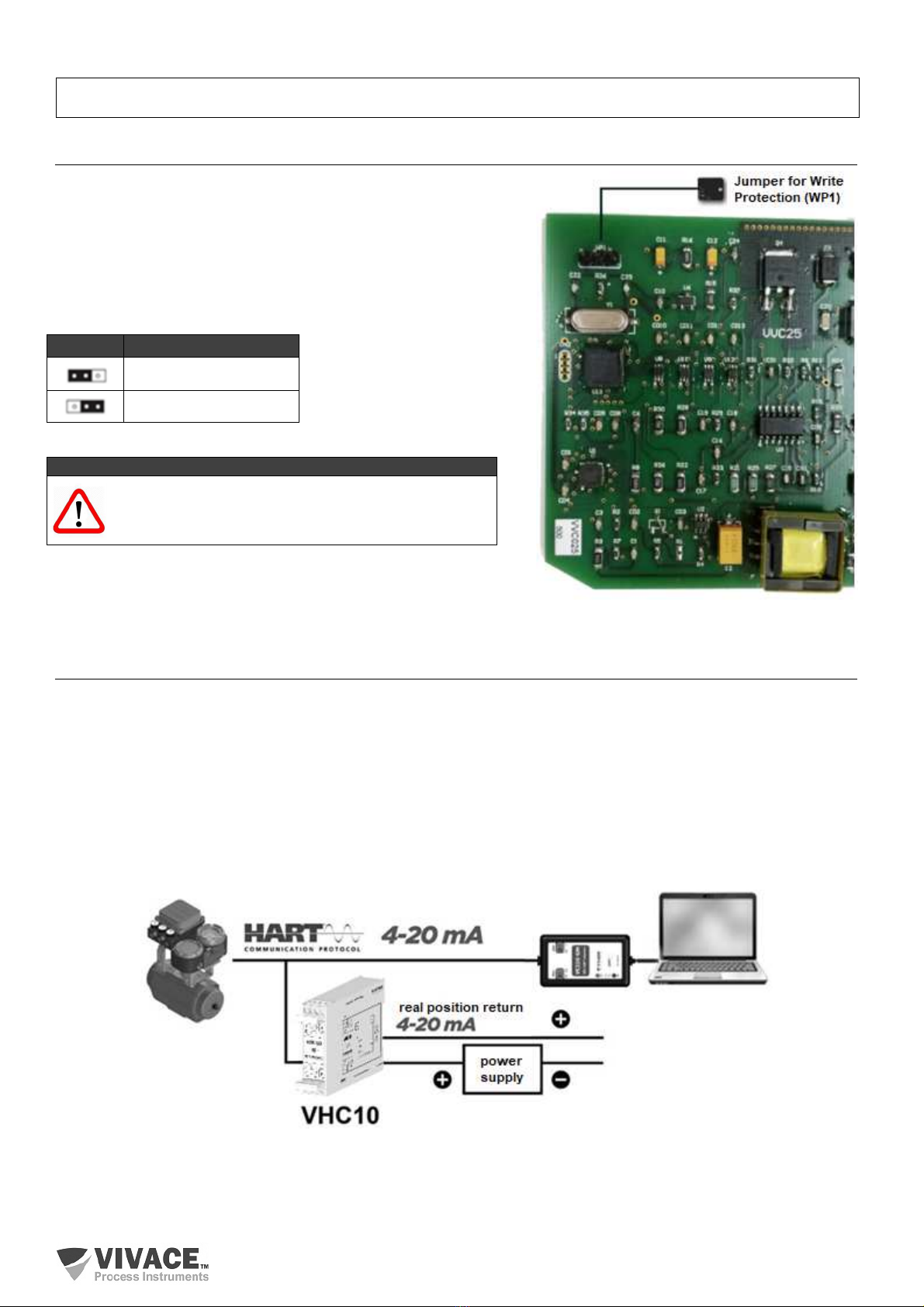
3.1. JUMPERS FOR LOCAL ADJUST AND WRITE PROTECTION
In addition to the software write protection function, using a
configurator, user can change the hardware protection (figure 3.1),
in order to ensure that no user can remotely modify their settings.
Software write protection does not disable hardware protection and
vice versa. For write protection to be disabled, both must be
disabled.
NOT
E
The default condition for write protection jumper is
DISABLED.
Figure 3.1 – Hardware write protection.
3.2. HART
®
PROGRAMMER
The configuration of the equipment can be performed using a programmer compatible with HART
®
technology.
Vivace offers VCI10 HART
®
line interfaces (USB or Bluetooth) as a solution for configuration and monitoring of
HART
®
line equipment.
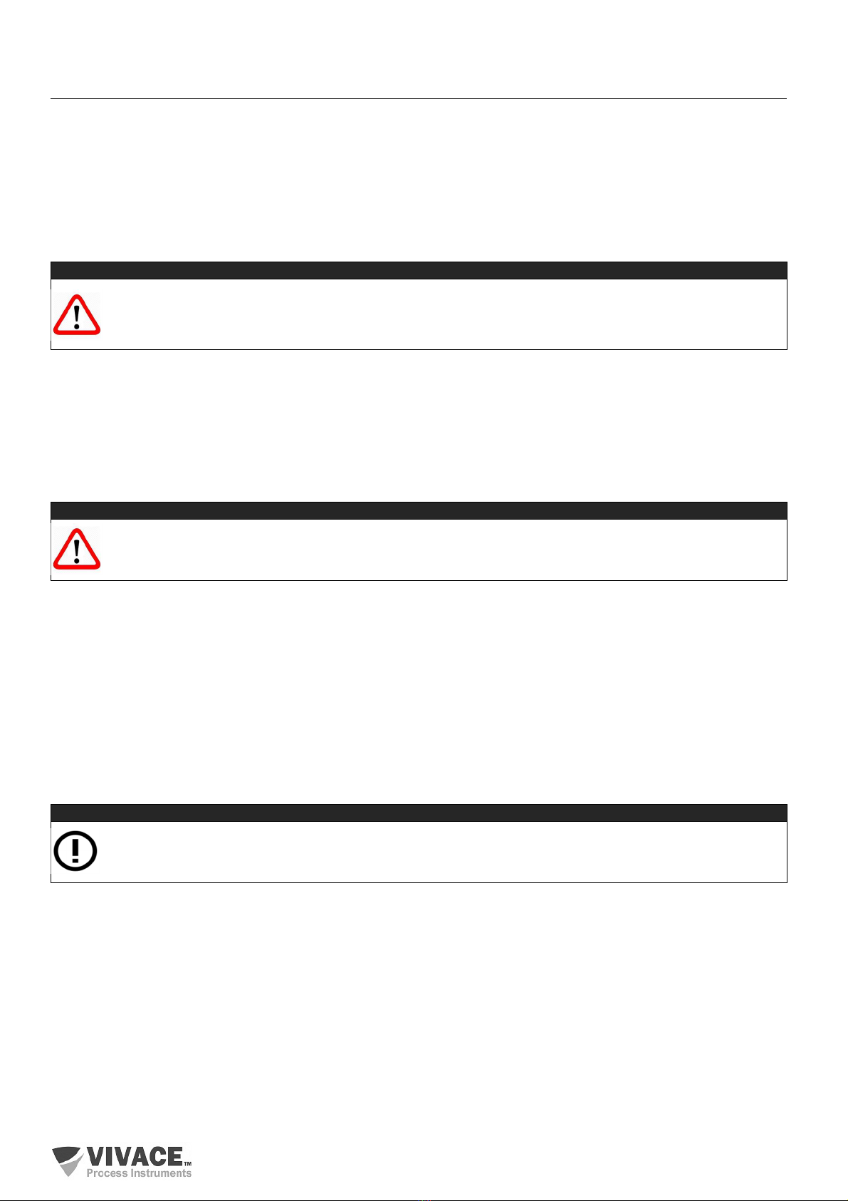
Figure 3.2 exemplifies the use of the USB interface with a personal computer that has HART
®
configurator software
installed, for communication with a valve positioner.
A 250Ωresistor must be used in series with the equipment power supply when the equipment to be monitored is
powered via voltage, if the source does not have this load internally, to enable HART
®
communication over the 4-20
mA current. Vivace interfaces already have this load internally.
Figure 3.2 – Installation of converter for monitoring a valve positioner – only 1 channel.
WP1 Write Protection
Enabled
Disabled
VHC10-P CONVERSOR HART
®
4 – 20 mA MAN AL DE INSTALAÇÃO, OPERAÇÃO, CONFIG RAÇÃO E MAN TENÇÃO
______________________________________________________________________________________________________________________________
9
3.3. CONFIGURATION PARAMETERS
Parameters are available for user configuration through a HART
®
programmer. In addition to the parameters inherent
to the protocol, there are some basic parameters to be configured before starting the converter: the address of the
equipment to be monitored, the codes of the variables to be monitored, units and working ranges for calculating the
currents.
The parameters inherent to the protocol concern the converter itself, basically dealing with its identification (Tag,
Description, Date, Address) and calibration of the currents to be used as output signals of the monitored variables.
For more details on each of these parameters and where to configure them, see section 3.5.
CONFIGURATION WINDOW
VHC10-P normally works as a "master" in order to monitor the "slave" equipment and generate currents proportional
to the monitored variables. So, converter will not receive HART
®
commands from another master, making it
impossible to configure it when in this mode.
To configure it, the user must follow the procedure below.
a. Reset VHC10-P converter
The converter will wait for configuration commands to be received. If no command is sent within 30 seconds", the
"master mode will be enabled automatically.
b. Localize the conversor
Using a HART
®
configurator, poll device at address one (1) – or at the address modified by user user.
c. Change mode to Configuration
In the "Settings" directory, change the converter mode to "Configuration". From this moment on, the user will be able
to make any configuration with peace of mind, without the converter going back to the "master" mode.
d. Configure addresses, variables and ranges
User must verify that the address of the "slave" equipment, the codes of the variables to be monitored, working
ranges and units are correct.
The variables to be monitored can be chosen among the dynamic variables (PV, SV, TV or QV) or by a variable-
specific code index (check the indexes available in the monitored product manual).
e. Change mode to Monitoring
In the "Settings" directory, change the converter mode to "Monitoring" (or "Enable Master Mode", according to the
configurator used). From this moment on, the user will no longer be able to configure the converter and it will work in
"master" mode.
CAUTION
As VHC10-P converter will be connected on the same HART
®
line as the equipment monitored, its default
address is one (1). Therefore, when using the HART
®
configurator for configuration, this address must be
entered by the user in the 'Polling Address' field.
CAUTION
If the converter enters monitoring mode and the user wants to change any configuration, the procedure
must be restarted.
NOT
E
Vivace configuration tools such as VMT-HART and converter DTM already send this command
automatically. In this case, the user can go straight to item d..
VHC10-P CONVERSOR HART
®
4 – 20 mA MAN AL DE INSTALAÇÃO, OPERAÇÃO, CONFIG RAÇÃO E MAN TENÇÃO
______________________________________________________________________________________________________________________________
10
IDENTIFYING SLAVE DEVICE
After installing the converter on the HART
®
network, user must configure the address of the equipment to be
monitored (0 to 15, for HART
®
6 or earlier; 0 to 63, for HART
®
7) and the variable codes of this equipment to be
converted to 4-20 mA current.
In the case of variables, user can choose between main dynamics (PV, SV, TV or QV) or manually enter the code of
the desired variable, if it is not one of the four above.
With these configurations completed, user will be able to activate the monitoring of the slave equipment ('Enable
Master Mode') in the “Configuration” menu, when the converter will start to try to identify the slave equipment at the
configured address.
In case of success, the monitoring of the configured variables will start automatically, generating the 4-20 mA output
currents proportional to the values configured in the parameters of the respective working ranges and current
calibrations (HART
®
standard).
CONFIGURATION EXAMPLE:
Converter: Address 1
Slave Device: Address 0
Monitored Variable 1: PV%
Variable 1 Unit: %
Variable 1 Range: 0% to 100%
Monitored Variable 2: SV
Variable 2 Unit: °C
Variable 2 Range: -20°C a 150°C
Table 3.1 – Example of monitoring for 2-channel converter.
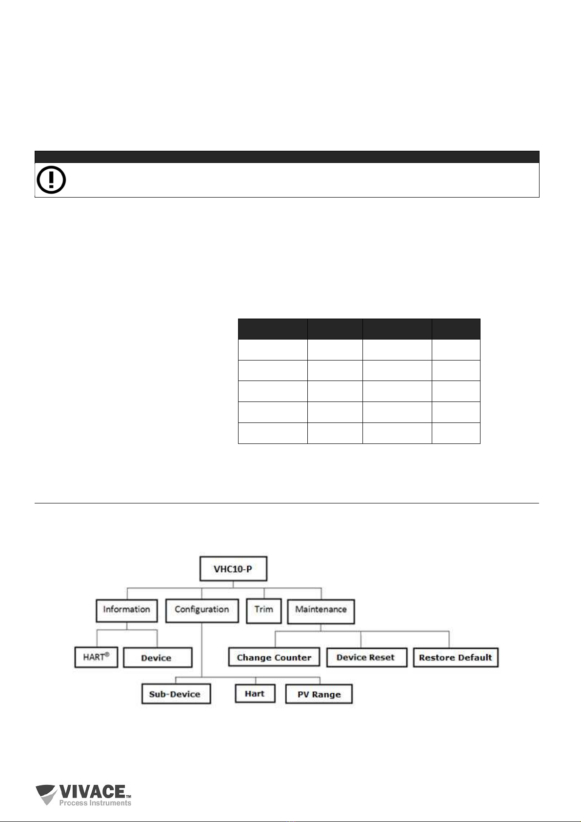
3.4. PROGRAMMING TREE FOR HART CONFIGURATOR
The programming tree is a tree-like structure with a menu of all available software features, as shown in the figure.
3.3.
Figure 3.3 – VHC10-P programming tree.
To configure the converter online, make sure it is correctly installed, with the proper supply voltage and a minimum of
250 Ωof line impedance, necessary for communication with the slave equipment (in the case of voltage-supplied
transmitters, only).
NOT
E
The codes for each variable must be provided by the manufacturer of each equipment.
VAR1 = PV% OUT1 VAR2 = SV OUT2
0,0% 4,0 mA -20,0
°C
4,0 mA
25,0% 8,0 mA 22,5
°C
8,0 mA
50,0% 12,0 mA 65,0
°C
12,0 mA
75,0% 16,0 mA 107,5
°C
16,0 mA
100,0% 20,0 mA 150,0
°C
20,0 mA

VHC10-P CONVERSOR HART
®
4 – 20 mA MAN AL DE INSTALAÇÃO, OPERAÇÃO, CONFIG RAÇÃO E MAN TENÇÃO
______________________________________________________________________________________________________________________________
11
INFORMATION
The main information about the converter can be accessed here.
HART
®
– The main equipment information regarding the communication protocol is found here, such as:
Manufacturer, Device Type, Device Profile, HART
®
Revision, Software Version and Order Code.
Device – Here are the main equipment information: Tag, Description, Message, Serial Number and Order Code.
CONFIGURATION
Here you configure the Converter Mode, as Master (monitoring) or Slave (configuration). Also the items in this menu
allow the following settings:
Sub-Device – Address and Variable Codes for the monitored device.
Range – Working Ranges (upper and lower points) and Units.
Hart – configures Current Mode, Safety Output, HART Master Mode, Write Protection and Communication
Preambles.
TRIM
User can adjust the output currents of the converter. Figure 3.4 shows the assembly diagram for the TRIM of the
current OUT1 of the VHC10-P. To trim the OUT2 current, just repeat the assembly of the figure, using the inputs of
terminals 3 and 4 of the converter.
MAINTENANCE
In this menu you can perform maintenance tasks for the converter, as described below.
Change Counter – Informs the change counters for each of the following drive parameters. It is also possible to
reset the counters in this directory.
Converter Address
Variable 1 Range
Variable 2 Range
Variable 1 Unit
Variable 2 Unit
Inferior Current Trim
Superior Current Trim
Slave Device Address
Variables 1 and 2 Codes
Software Write Protection
Safety Output
Device Reset – resets converter via software.
Restore Default – restores factory default values to
configuration and calibration parameters.
Figure 3.4 – Mounting for OUT1 current trim.
CAUTION
Make sure the converter is in Configuration Mode (see the 'Configuration Window' item) before initializing
the settings.

VHC10-P CONVERSOR HART
®
4-20 mA MAN AL DE INSTALAÇÃO, OPERAÇÃO, CONFIG RAÇÃO E MAN TENÇÃO
______________________________________________________________________________________________________________________________
12
3.5. SAFE OUTPUT
The converter has a specific configuration to independently direct the output currents to a safety value, according to
the user application.
This value is used whenever the slave equipment stops responding to monitoring commands, when configurator
enters configuration mode or when the user uses the local adjustment with the magnetic tool.
The user can configure the following safety outputs, according to the NAMUR NE-43 standard:
HIGH – sets the respective safety output to 20.50 mA (103.125%);
LOW – sets the respective safety output to 3.8 mA (-1.25%);
LAST VALUE – sets the respective safety output to the last valid value read.
Converter will return to indicate the current proportional to the respective monitored variable as soon as the
connection with the slave equipment is re-established or when the configuration mode is ended.
3.6. FDT/DTM CONFIGURATION
Tools based on FDT/DTM (Ex. PACTware
®
or FieldCare
®
) can be used for information, configuration, monitoring and
visualization of diagnosis on devices with HART
®
technology. Vivace makes available on its website
(www.vivaceinstruments.com.br) DTMs of all its equipment from the line with the protocols HART
®
and Profibus PA.
PACTware
®
is proprietary software of the PACTware Consortium and can be found on the website:
http://www.vega.com/en/home_br/Downloads
The following figures show some of the VHC10-P DTM screens using the Vivace VCI10-UH interface with
PACTware
®
. Note that the directory with menus available for the DTM (OnLine Parameterize) follows the format of
the configuration tree displayed in the item 3.4 (figure 3.3).
Figure 3.5 – Variable configuration screen. Figure 3.6 – Monitoring configuration screen.
NOT
E
For complete details of each of the functions provided by the converter via DTM, see section 3.4 –
Programming Tree for HART Configurator.
VHC10-P CONVERSOR HART
®
4-20 mA MAN AL DE INSTALAÇÃO, OPERAÇÃO, CONFIG RAÇÃO E MAN TENÇÃO
______________________________________________________________________________________________________________________________
13
4 TECHNICAL CHARACTERISTICS
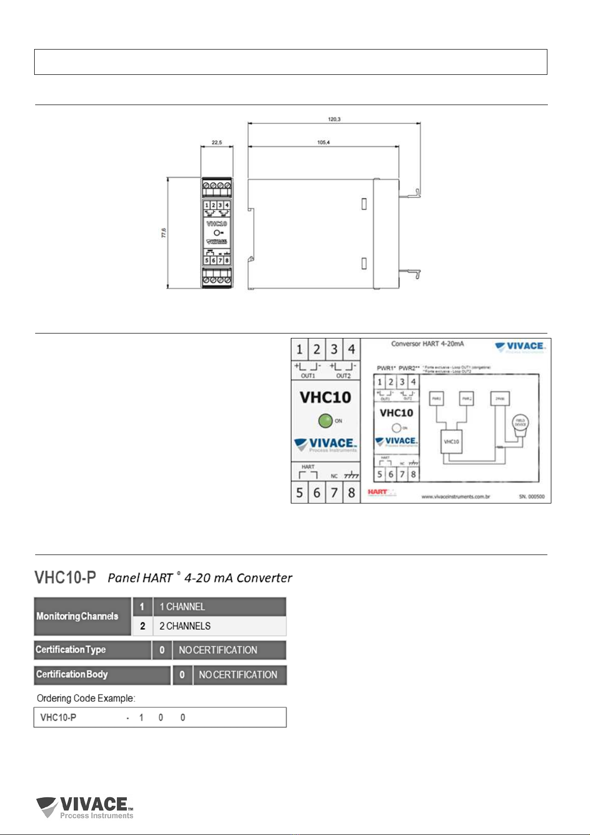
4.1. CASE DIMENSIONS
Figure 4.1 – Dimensions of housing case.
4.2. IDENTIFICATION
VHC10-P has an identification tag attached to its front
face, specifying model, manufacturer and connections,
as shown in Figure 4.2. It also has a side label with the
converter connection diagram and the equipment serial
number.
The indications of the connections of the HART
®
channel with the equipment to be monitored, of the
power supplies and current outputs are also indicated on
the labels.
Figure 4.2 – Identification tags for VHC10-P – 2-channel
model.
4.3. ORDERING CODE
VHC10-P CONVERSOR HART
®
4-20 mA MAN AL DE INSTALAÇÃO, OPERAÇÃO, CONFIG RAÇÃO E MAN TENÇÃO
______________________________________________________________________________________________________________________________
14
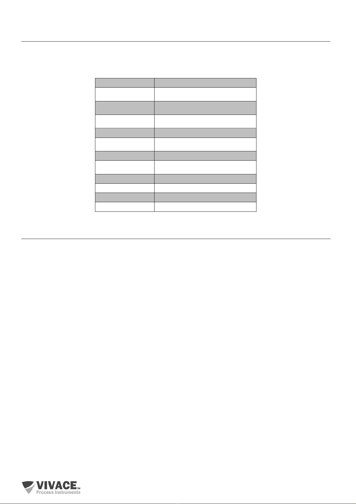
4.4. TECHNICAL AND PHYSICAL SPECIFICATIONS
The main technical and physical characteristics of the converter are listed in Table 4.1. These are important
references that must be analyzed before installing the converter to the user's system, especially with regard to
supply voltage, temperature and mechanical connection.
Table 4.1 – Specifications for VHC10-P converter.
4.5. SPARE PARTS
4-Way VHC10-P Protection Connector (upon request).
Accuracy ± 0,03% of calibrated span
Comunication Protocol
HART
®
7 (compatible with previous versions)
Output Current Up to two 4-20 mA channels, according to
NAMUR NE43
Power Supply 12 to 45 Vdc, not polarized, with transient
protector
Temperature Limits -10 to 70°C (14 to 158°F)
Configuration Remote configuration using tools based on
EDDL or FDT/DTM
Write Protection Hardware and software
Hazardous Area
Certification
Not certified
Protection Degree IP00 / IP66 (installed)
Mounting Panel, DIN 43880 rail
Case Material Injected ABS Plastic
Approximated Weight 300 g

VHC10-P HART
®
4-20 mA CONVERTER INSTALLATION, OPERATION, CONFIG RATION AND MAINTENANCE MAN AL
______________________________________________________________________________________________________________________________
15
5 WARRANTY
5.1. GENERAL CONDITIONS
Vivace ensures its equipments from any defect on manufacturing or component quality. Problems caused by misuse,
improper installation or exposure to extreme conditions are not covered by this warranty.
User can repair some equipments by replacing spare parts, but it is strongly recommended to forward it to Vivace for
diagnosis and maintenance in cases of doubt or impossibility of correction by the user.
For details about the product warranty, see the general term warranty on Vivace website:
www.vivaceinstruments.com.br.
5.2. WARRANTY PERIOD
Vivace ensures the ideal operating conditions of their equipment by a period of two years, with full customer support
regarding to installation, operation and maintenance for the best use of the equipment.
It is important to note that even after warranty period expires, Vivace assistance team is ready to assist customer
with the best support service, offering the best solutions for the installed system.

VHC10-P HART
®
4-20 mA CONVERTER INSTALLATION, OPERATION, CONFIG RATION AND MAINTENANCE MAN AL
______________________________________________________________________________________________________________________________
16
APPENDIX I – TECHNICAL ANALYSIS REQUEST
FSAT
Technical Analysis Solicitation Form
Company: Unit/Department: Shipping Invoice nº:
Standard Warranty: ( )Yes ( )No Extended Warranty: ( )Yes ( )No Buying Invoice nº:
COMMERCIAL CONTACT
Complete Name: Position:
Phone and Extension: Fax:
e-mail:
TECHNICAL CONTACT
Complete Name: Position:
Phone and Extension: Fax:
e-mail:
EQUIPMENT DATA
Model: Serial Num.:
PROCESS INFORMATION
Environment Temperature (ºC) Work Temperature (ºC)
Min: Max: Min: Max:
Operation Time: Fail Date:
FAIL DESCRIPTION: Here user should describe in detail the observed behaviour of product, frequency of fail occurence and
repeatability. Also, should inform operational system version and a quick description of control system architecture where the
equipment was installed.
ADDITIONAL OBSERVATION:

VHC10-P HART
®
4-20 mA CONVERTER INSTALLATION, OPERATION, CONFIG RATION AND MAINTENANCE MAN AL
______________________________________________________________________________________________________________________________
17
Table of contents
Other Vivace Media Converter manuals


Popular Media Converter manuals by other brands


AIMS Power
AIMS Power CON120AC36/48VDC user manual

Extron electronics
Extron electronics II Specification sheet

Crestron
Crestron DVPHD Operation guide

Vdwall
Vdwall LVP615 series Operation application instruction

Optoma
Optoma ThemeScene HD3000 user guide

Schumacher Electric
Schumacher Electric SI1479 owner's manual


