Vivace MPEG2 User manual
Powered by
Vivace MPEG2 Encoder
with Stat-Mux
User Manual
August 3, 2018
Anywave Vivace MPEG2 Encoder User Manual V1.9

Anywave Communication Technologies
Vivace MPEG2 Encoder User Manual
1
1/ 37
Powered by
Table of Contents
1 Introduction............................................................................................................................. 2
2 Connection Setup Overview.................................................................................................... 3
3 Hardware Interface Specifications .......................................................................................... 4
4 Management Interface............................................................................................................ 5
5 Configuration........................................................................................................................... 6
5.1 Overview.......................................................................................................................... 6
5.2 Video Options.................................................................................................................. 7
5.3 Audio Options.................................................................................................................. 7
5.4 Transport Options............................................................................................................ 8
5.5 Advanced Parameter Options ....................................................................................... 10
5.5.1 Advanced Video Options ....................................................................................... 10
5.5.2 SDI source options................................................................................................. 12
5.5.3 Advanced Audio Options ....................................................................................... 12
5.5.4 SDI source option .................................................................................................. 13
5.5.5 Advanced Transport Options................................................................................. 13
5.6 SPLITTER (optional component on certain models)...................................................... 14
6 CONTROL MENU.................................................................................................................... 18
7 EAS......................................................................................................................................... 21
8 OUTPUT MUX ........................................................................................................................ 22
8.1 PSIP input into the MUX ................................................................................................ 23
8.2 Output Mux Settings ..................................................................................................... 23
9 Management Page ................................................................................................................ 24
9.1 UPDATE TAB .................................................................................................................. 26
10 VIVACE ENCODER - PRODUCT MODELS AND CONNECTIONS ........................................... 30
11 Vivace ENCODER - PRODUCT CONFIGURATIONS .............................................................. 33

Anywave Communication Technologies
Vivace MPEG2 Encoder User Manual
2
2/ 37
Powered by
1Introduction
Vivace is an ATSC compliant, real time MPEG2/AC3 encoder with integrated Statistical
Multiplexing (Stat-Mux). Vivace models include SD, and/or HD support (depending on
model), Emergency Management (EAS) signal detection and insertion, and other
advanced features.
The diagrams in Appendix A show the various signal connections for each model
available. Refer to your specific model diagram.
Vivace is setup for simple plug and play operation. Simply power up the unit, plug in
your input signals, and Vivace will auto detect the signal and encode it.
A web based user interface is provided for changing video, audio, and other settings for
the encoder. In order to access this user interface, you must configure the ethernet
ports on the unit to work within your IP network. Network setup instructions are provided
with the unit.

Anywave Communication Technologies
Vivace MPEG2 Encoder User Manual
3
3/ 37
Powered by
2Connection Setup Overview
The generalized signal flow is shown in the diagram below. Video and Audio inputs are encoded
into a single ATSC compliant MPEG2 Multiplexed Transport Stream. The output interface
depending on Vivace model is ASI or IP, or both.
Vivace is controlled from a web based interface. Each Vivace is shipped with factory settings on
the Ethernet ports. Please refer to the Vivace Setup Guide shipped with each unit which
describes how to initially setup your encoder.

Anywave Communication Technologies
Vivace MPEG2 Encoder User Manual
4
4/ 37
Powered by
3Hardware Interface Specifications
The following interface types are available depending on the model.
Analog Video/Audio Inputs:
Composite Video Input (CVBS): BNC male connector. 75 Ohm
Stereo Audio Input : 3.5 mm ; -10 dBV (default models)
Optional: +4dBu hardware feature available at time of ordering. This includes XLR
female to 3.5 mm connection cables
Digital SDI Inputs: HD-SDI and SD-SDI inputs. SMPTE 259M-C and SMPTE 292M. 75
Ohm BNC
Ethernet Interfaces: 10/100/1000Mbps baseT
ASI (input or output): DVB-ASI. 75 Ohm BNC
For Initial Setup Only (see setup guide): VGA and USB 2 interfaces (for USB keyboard
use during initial setup)

Anywave Communication Technologies
Vivace MPEG2 Encoder User Manual
5
5/ 37
Powered by
4Management Interface
To control the encoder and make configuration changes, use a web browser on any PC
connected to the IP network of the encoder. Enter the URL
http://VIVACE-IP
where VIVACE-IP is the IP address you have configured for your encoder.
The web interface is organized with a top row of menus, as seen below.
Configuration Menu: select this to change channel settings such as bit rate and
resolution.
Control Menu: select this to start or stop individual channels on the encoder and
monitor picture thumbnail and other statistics of running channel
Output Mux: select this to configure and start or stop the MPEG2 MPTS mux.
Monitor : Provides graphical feedback of bitrate of channels running
Log : Encoder detailed log messages
Management: Provides encoder IP configuration settings, and other system level
management features.
Splitter(some units): The splitter component receives MPTS signals (via ASI or
IP) and extracts individual SPTS channels for input channels that can be used.
Anywave Communication Technologies
Vivace MPEG2 Encoder User Manual
6
6/ 37
Powered by
5Configuration
5.1 Overview
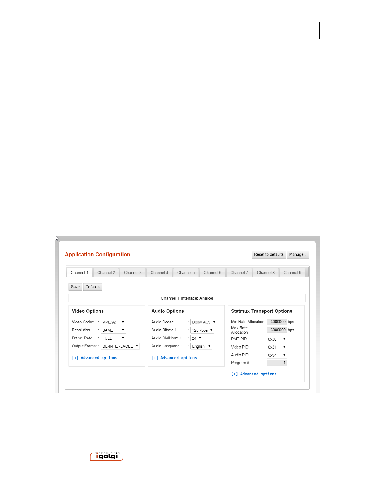
The configuration page of the User Interface is shown below. Each channel on the
encoder has its own configuration menu. (the example below shows an 8 channel
encoder model)
To change a configuration for any channel, select the tab that goes with that channel.
Each channel is associated with a specific input interface. Refer to the model you have
to associate the physical interface with the channel number.
Once you make your changes to the parameters you wish, you must select the save
button. The configuration changes do not take effect until you start or restart a channel
on the Control page. A warning is shown on screen when changes are made but not
saved. However, if you ignore that warning and navigate to a different menu, then any
changes made will be lost.
When first setting up channels, it is suggested to select “reset to defaults” to have a
good starting point with typical values.There is also a defaults button for individual
channels, if you wish to only set defaults for a given channel.

Anywave Communication Technologies
Vivace MPEG2 Encoder User Manual
7
7/ 37
Powered by
5.2 Video Options
Video Codec: This selects the video compression standard used for this channel.
MPEG2 is the default. H.264 is optional on some models. Certain product models have
only MPEG2, or H.264 or both.
Resolution: This is the output resolution for the channel in horizontal x vertical pixel
units.
Standard Definition default setting is 720x480.
High Definition can be 1920x1080 or 1280x720. The default is 1920x1080, but you
may need to change this depending on your source.
Other resolutions are available which are smaller than HD or SD inputs. If you select
one of these smaller resolutions, the video signal will be down scaled.
Frame Rate: This is the output frame rate for the channel in frames per second (fps)
units.
Full: this will maintain the same frame rate as the input signal.
½ or ¼ : these will reduce the frame rate by these associated amounts.
oFor SD NTSC sources, the ½ setting will result in 15 fps, and the ¼ setting
will result in 7.5 fps.
oFor HD 1920x1080i, the ½ setting will result in 15 fps, and the ¼ setting will
result in 7.5 fps
oFor HD 1280x720p, the ½ setting will result in 30 fps, and the ¼ setting will
result in 15 fps.
o
Output Format: This is the output frame structure for the channel.
De-Interlaced: this setting will de-interlace the input signal to create a progressive
output signal. The de-interlacer is a high quality multi-frame motion compensated
de-interlacer.
Same As Input : Select Same As Input to keep the frame structure the same as the
incoming signal
5.3 Audio Options
Audio Codec: Several audio compression standards are available on different product
models. The default audio codec is AC3. Codecs available on certain models include
AAC-LC, AAC-HE, MPEG1-layer1/2, MPEG2-layer1/2, and MP3.
Bitrate: Several audio bitrate value options for the AC3 encoder are provided in Kbps
Stereo signals are typically encoded at 128,192, or 256 Kbps
If you have a model with HD signals, 5.1 audio is supported. Typical bit rates used for
5.1 are 384, 512, or 640 Kbps

Anywave Communication Technologies
Vivace MPEG2 Encoder User Manual
8
8/ 37
Powered by
Audio Dialnorm: range 1-31: Dialnorm (Dialog Normalization) is an AC3 parameter that
defines the playback gain of -30 to 0 dB (unity). The value of the Dialnorm parameter in
the AC-3 elementary bit stream shall indicate the level of average spoken dialogue
within the encoded audio program.
Audio Language: Provides language descriptor for the audio stream.
Second Audio Program (SDI inputs). SDI inputs have second audio input capability
which can support second language or other applications.
To enable the second audio program on these channels, select “audio bitrate 2” to a
desired bit rate.
To disable the second audio program, select “disable” on the Audio Bitrate 2 option.
5.4 Transport Options
Total Mux Rate: This is the total bitrate (bandwidth) in bits per second (bps) for the
channel. The supported range for SD signals is 3,000,000 to 10,000,000 bps (3-10
Mbps).
Without Statmux, the video bit rate will be automatically calculated based on the Total
Mux Rate minus the Audio Bitrate minus the Transport Packet overhead. Transport
overhead includes packetization into MPEG TS format for ATSC compliance and
associated synchronization packets such as PCRs.
With StatMux Transport Options
Min Rate Allocation: This is the target minimum bitrate (bandwidth) in bits per second
(bps) for the channel.
Max Rate Allocation: This is the target maximum bitrate (bandwidth) in bits per second
(bps) for the channel.
Note: The video bit rate will be automatically calculated based on the Total Mux Rate
minus the Audio Bitrate minus the Transport Packet overhead. Transport overhead
includes packetization into MPEG TS format for ATSC compliance and associated
synchronization packets such as PCRs.
Example Suggested Bit Rates:
Depending on the number of channels, the picture format (SD or HD), and the output
total mux rate, the settings for your min and max will vary.
The minimum bit rate assigned to all channels cannot add up to more than the Mux
Rate.
To assign a higher priority to a given channel compared to another, provide a higher
minimum bit rate to the higher priority channel.
Example1: 9 SD Channels and total Mux rate of 19.39 Mbps: min 1.25 Mbps, max 3
Mbps

Anywave Communication Technologies
Vivace MPEG2 Encoder User Manual
9
9/ 37
Powered by
Example2: 2 HD Channels and 1 SD channel:
HD min: 6 Mbps and Max 14 Mbps
SD min: 1.25 Mbps and Max 3 Mbps
PMT, Video and Audio PID
PID (Program IDentification) are unique IDs for each element in a MPEG TS.
The default values for the PMT,Video,and Audio PIDs for each channel are offset by
0x10 units (hexadecimal). For example
Channel 0: 0x30, 0x31, 0x32
Channel 1: 0x40, 0x41, 0x42
You may change these PIDs to other values, but they must be unique ID values for all
channels.
The user interface will warn you if you choose a value that is not unique based on all
channel configurations. The warning will occur when you attempt to save a channel
configuration with such a conflict. A dialog box will appear (example below). In this
case a channel PID was in conflict with the same PID value from channel 7.
Program #
The program # is a unique number for each channel. This parameter is included in the
MPEG-TS stream and must be unique for each channel.
The user interface will warn you if any program numbers conflict across channels.

Anywave Communication Technologies
Vivace MPEG2 Encoder User Manual
10
10 / 37
Powered by
5.5 Advanced Parameter Options
The advanced parameter options can be set by selecting the blue “advanced options” for
each type (Video, Audio, Transport). Below is shown with all of these options opened.
5.5.1 Advanced Video Options
# B frames : The default setting is 2. Allowed settings are 0,1 or 2. In general, the
higher setting will result in increased compression, and the video quality is improved for
a given bit rate.
GOP Length: The distance in frames between Intra frames. Typical value is 30 or 60.
In general, the higher values provided better compression.
Closed Captions: When On, captions are included in the encoder output if the CVBS or
SDI source signal has caption information.
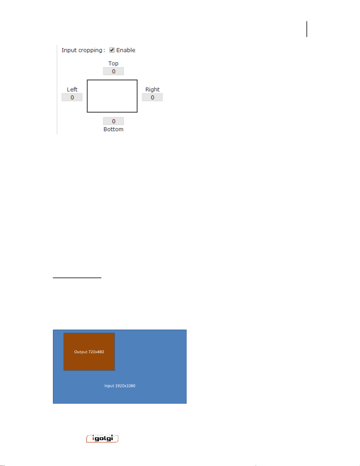
Input Cropping. When enabled a cropping window selection is available. Each entry
provides cropping offset from Top and Left of the video frame.
Anywave Communication Technologies
Vivace MPEG2 Encoder User Manual
11
11 / 37
Powered by
If cropping is used, it is recommended to crop to pixel boundary positions divisible by 16
to align on macroblock boundaries of the compressed video stream. This provides the
best video quality during cropping.
If the input signal is cropped and the output resolution setting is different, then the video
will be cropped and then scaled to the requested output resolution setting. Therefore,
you do not need to crop to an exact output resolution, the correct scaling will be applied.
The Top and Bottom Parameters are in pixel units measured from the top of the
incoming Frame.
The Left and Right Parameters are in pixel units measured from the left of the incoming
Frame.
Cropping Example
Input HD 1920x1080 frame
Desired Output SD 720x480 frame, from upper left section of input Frame
Cropping settings
Top 16 Bottom 496
Left 128 Right 848

Anywave Communication Technologies
Vivace MPEG2 Encoder User Manual
12
12 / 37
Powered by
PreFilter Strength: An optional video prefilter is available. This can be used to reduce
the high frequency noise of an incoming signal if needed. Filtering noise can provide a
higher quality overall picture when encoding at low bit rates for MPEG2. Filter Strength
of Low, Medium and High are available.
Brightness: The default setting is 128. Allowed settings are 0-255. Increase or
decrease the value will increase or decrease the luminance level of the picture.
Hue: The default setting is 0. Allowed settings are -127 to 128. Increase or decrease
the value will shift the color values within the spectrum of defined colors. Use this for
course color correction when needed.
Contrast: The default setting is 68. Allowed settings are 0-127. Increase or decrease
the value will increase or decrease the sharpness and separation of objects.
Saturation: The default setting is 64. Allowed settings are 0-127. Increase or
decrease the value will increase or decrease the color intensity.
5.5.2 SDI source options
If the encoder model you have includes SDI inputs, these options are also available:
Field Order: top field or bottom field first for SDI inputs. Default is top field first.
Line 21 CC data rate: adjustment for the closed caption data rate for SDI inputs with line
21 cc data.
Output format: interlaced or progressive option
Caption Search: Auto, VANC608 , or Line21 Default mode is Auto which will search
both the VANC for 608 captions and line21 for analog captions. If you know what type of
closed caption format your SDI input is, you can select it.
5.5.3 Advanced Audio Options
Audio Volume: The default setting is 100%. Allowed range is 0 to 200%. This control
will apply a static increase or decrease to the volume level of the audio signal.
Audio AGC::The Audio Grain Control (AGC) is an optional feature that supports audio
loudness level processing compliant with the CALM ACT. The AGC allows automatic,
dynamic audio level adjustment for individual channels. Each channel configuration
allows the use of this feature, with different parameter control.
The setting options are:
Disabled => no limiting

Anywave Communication Technologies
Vivace MPEG2 Encoder User Manual
13
13 / 37
Powered by
Any of the following settings will ensure CALM ACT compliance. TheTV_5B_GEN setting
is the default setting that is recommended.
TV_5B_GEN : This is the recommended setting that provides moderate degree of
dynamic range processing and works with a wide variety of content.
TV_5B_LIGHT: similar to the GEN setting, but has a slower transition on sharp loudness
changes.
TV_5B_HEAVY: Stronger reduction to loudness changes but results in less dynamic
sound.
TV_5B_Loud : Strongest loudness suppression.
IT_LOUD_LIMIT : this provides a slow adjustment to the program loudness. This is
useful for live applications where the program loudness may be changing slowly.
Protect Limit : This provides a simple limiter function to protect against overload.
5.5.4 SDI source option
Audio Group: Audio group for input audio.
Audio Pair: Audio pair (stereo pair) for input audio signal
.
5.5.5 Advanced Transport Options
PAT: The Program Association Table of a MPEG-TS. Default value is 80 milliseconds.
This defines the repetition rate of a PAT table in the MPEG-TS. Higher value reduces
the overhead of the PAT component on the overall MPEG-TS bandwidth, hence
providing slightly more room for audio and video signaling.
PMT: The Program Map Table of a MPEG-TS. Default value is 350 milliseconds. This
defines the repetition rate of a PMT table in the MPEG-TS. Higher value reduces the
overhead of the PMT component on the overall MPEG-TS bandwidth, hence providing
slightly more room for audio and video signaling.
PCR: The Program Clock Reference of a MPEG-TS. Default value is 40 milliseconds.
This defines the repetition rate of the PCR in the MPEG-TS. Higher value reduces the
overhead of the PCR component on the overall MPEG-TS bandwidth, hence providing
slightly more room for audio and video signaling. However, lower values may be needed
for some networks with high jitter downstream of the encoder (for example IP network
connections add jitter, so a lower value may be needed).

Anywave Communication Technologies
Vivace MPEG2 Encoder User Manual
14
14 / 37
Powered by
5.6 SPLITTER (optional component on certain models)
The Splitter is an MPTS Program De-multiplexer, and ASI/IP to IP router.
The Splitter can take IP MPTS MPEG2-TS streams from the external Ethernet input, or
ASI input. The Splitter then de-multiplexes programs in a MPTS to individual SPTS
MPEG2-TS streams. These SPTS streams can be configured to be used as inputs for
the encoder.
The splitter also features a discover mode to identify what programs exist in an incoming
stream and provide information on the stream construction and codecs.
Operation
The Splitter can be accessed from HTTP user interface by selecting the “Input Splitter”
name on the top of the user interface.
The Splitter has the following main controls
Start : to turn on the Splitter Function
Stop : to stop the Splitter Function
Restart : to restart a Splitter channel
Status : to open detail real time stream information on running splitter channels
Save Configuration : save the configuration of the Splitter settings. This is best done
when the splitter is not running. If you change configuration of the Splitter while
running, a dialog box will appear asking if you want to save these new settings. If yes,
the splitter channels which have had configurations changed will be stopped and
restarted at that time.
Defaults: If selected, the user will be prompted to set all channels to default settings,
then these can be saved. Default settings set all output IP/ports to loopback and
incremented non-conflicting ports.
For each Channel, there are these parameters to configure
oInput Interface : ASI or IP or Tuner.
For IP input, multicast, unicast, and loopback address supported.
Set IP to 0.0.0.0 for generic unicast input, and 127.0.0.1 for
loopback input.
0.0.0.0 will catch all unicast inputs with a matching port.
oDiscover => once an input port is defined, you can select the Discover button.
After a few seconds, a Table will appear in the “Output” section that lists
all the incoming programs on the input port. For each program, PIDs,
stream type, and codec is displayed.
oNOTE: DISCOVER will not function if the splitter is already running. You
must stop the channel to run discover.

Anywave Communication Technologies
Vivace MPEG2 Encoder User Manual
15
15 / 37
Powered by
oOutput Format:
UDP or RTP. Both use MPEG2-TS , but RTP includes the
addition of RTP headers in the stream.
NIC: for systems with multiple Ethernet NIC interfaces, you can
select any NIC for each SPTS output. You can also select “lo” for
loopback output.
Setting a specific NIC with 127.0.0.1 also will result in
loopback
IP/port setting. Each program will be output to a different IP/port
as a SPTS. multicast, unicast, and loopback address supported)
In order for the Encoder to use the splitter output, the splitter must
be configured to use eth0 or loopback, with address 127.0.0.1 and
port 8000, 8100, 8200, etc.
PMT Passthrough or Rewrite:
Passthrough mode simply keeps the PAT/PMT structure of
the incoming stream and the outgoing SPTS has just 1
element in the PMT
Rewrite: creates a new PAT/PMT for the stream with new
PIDS.
The user interface of the Splitter is shown below with a step by step example.
Step 1: Configure input interface on channel 0 (or other channels) In this example we
configure it for ASI input.

Anywave Communication Technologies
Vivace MPEG2 Encoder User Manual
16
16 / 37
Powered by
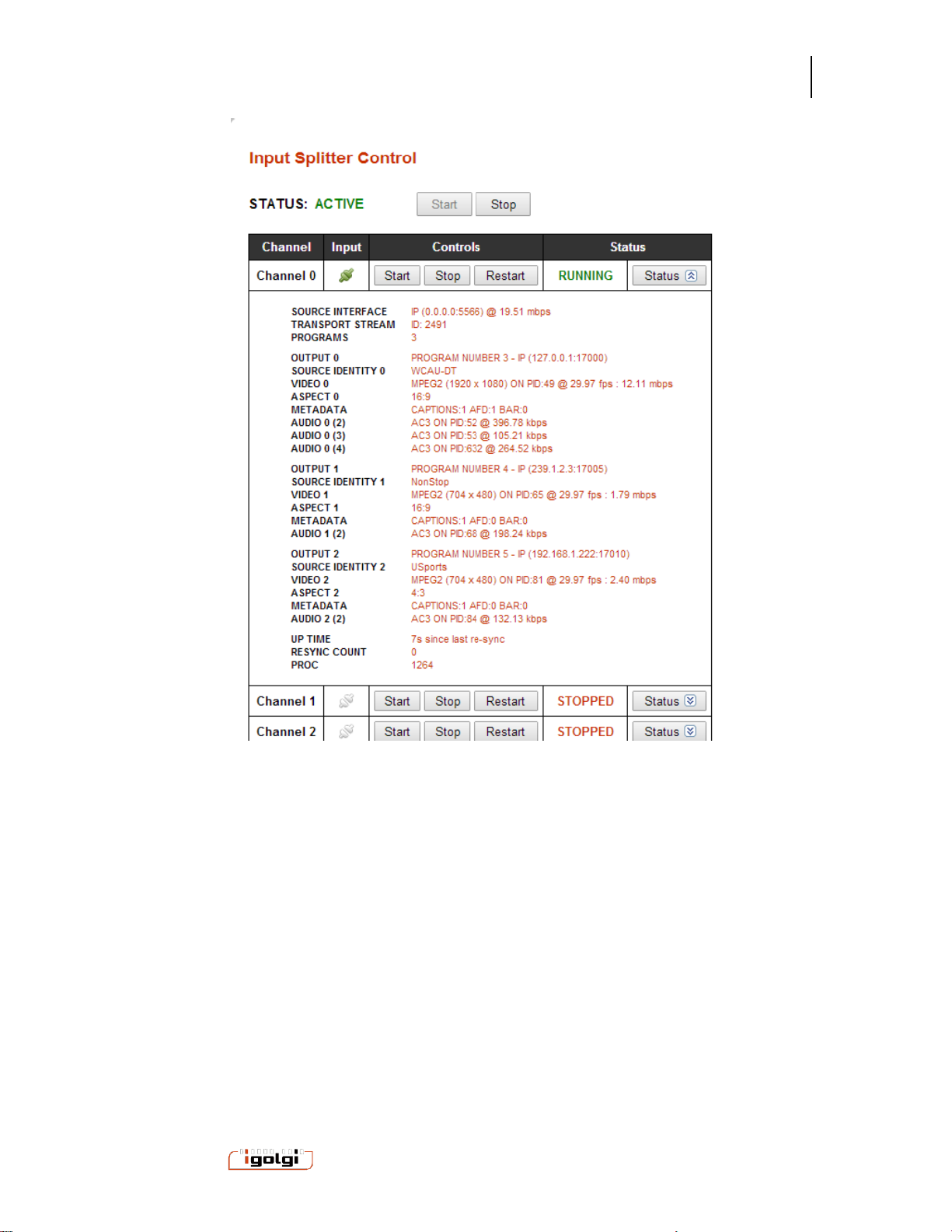
Step 2: Select Discover Button, and if an MPTS is found the stream information is
shown.
Step 3: Define output settings for each SPTS. Then select “Save Configuration”
Step 4: Start the splitter and monitor real status.
Anywave Communication Technologies
Vivace MPEG2 Encoder User Manual
17
17 / 37
Powered by
Configuration Notes
The Splitter MPTS places each program in the order of the Input Streams
incoming MPTS PAT/PMT table.
Anywave Communication Technologies
Vivace MPEG2 Encoder User Manual
18
18 / 37
Powered by
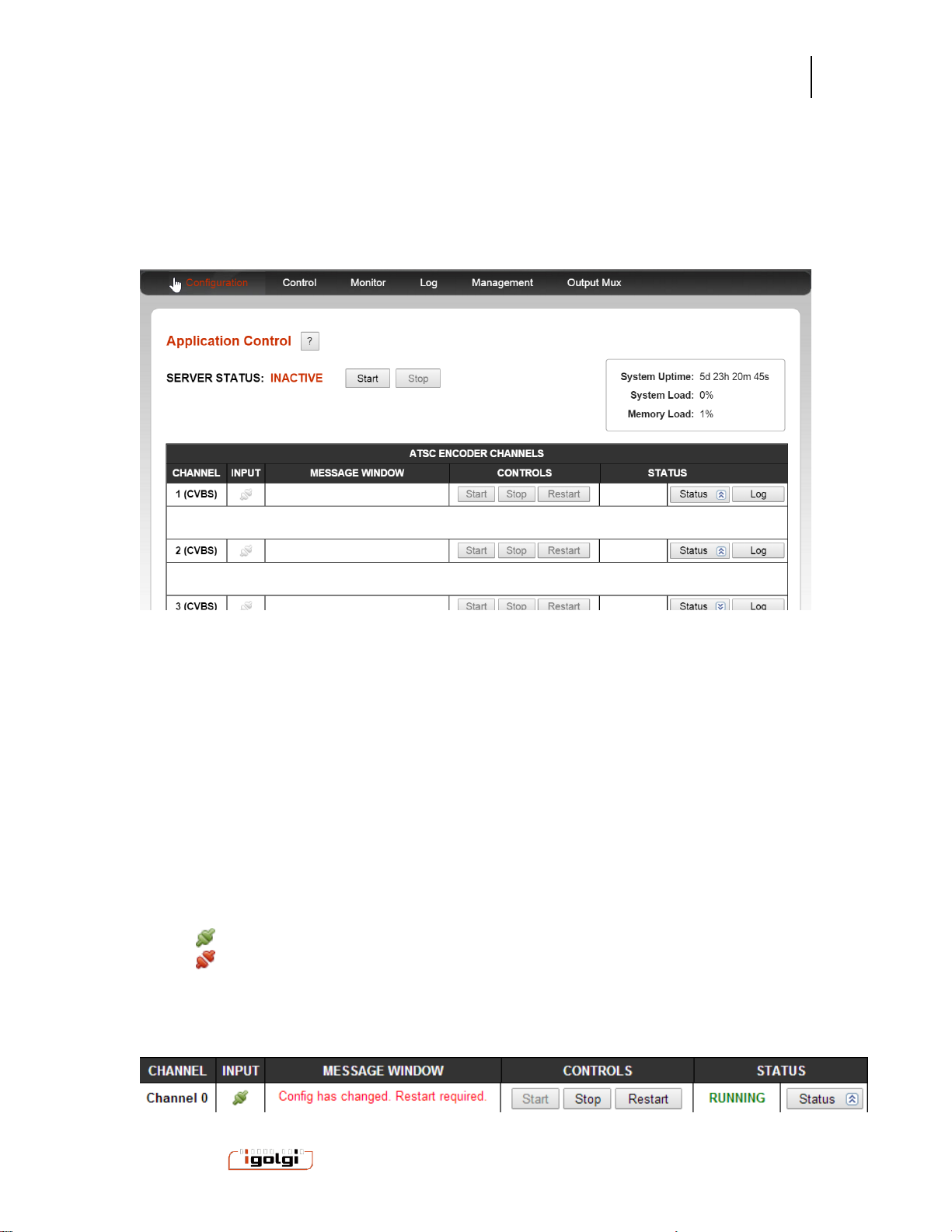
6CONTROL MENU
The control menu provides start and stop control for all the input channels. This menu
also provides real time feedback of the channels that are running, including a thumbnail
image that is updated every 5 seconds.
SERVER STATUS: This is a global ON/OFF control for the encoder. If the system is
“INACTIVE” then select the Start button to change it to ACTIVE. The encoder will not run unless
the SERVER STATUS is listed as ACTIVE.
System Uptime, load and memory load provide machine level status information.
You can start or stop any individual channel with the channel start and stop buttons. Each
channel is listed as a row in a table. The columns of the table are the following:
Channel: Each channel represents a pair of physical connectors for audio and video signals. The
channel numbers correspond to the labels on the capture system connectors.
Signal: Denotes the composite signal status for the channel.
: A input signal is being properly recognized
: No input signal is detected.
Message Window: System warning messages will appear here. For example when a
configuration is changed, then the channel needs to be restarted before the changes take effect.

Anywave Communication Technologies
Vivace MPEG2 Encoder User Manual
19
19 / 37
Powered by
Controls: Start and Stop buttons to start and stop capture on the channel. Restart can be used in
the case where configuration has been changed on a running channel and the channel needs a
restart.
Status: The channel high level status is shown as these status
STOPPED: Channel is not encoding
RUNNING: Channel is encoding
Detailed Status information is available with the Status button. When you select this
a variety of channel input and output signaling information is shown and updated in
real time.
Log:The channel specific log information is shown in a pop up dialogue window.
An example control page is shown here. A thumbnail of the processed video is
updated every 5 seconds.
Table of contents
Other Vivace Media Converter manuals


Popular Media Converter manuals by other brands

Black Box
Black Box AVSC-VGA-HDMI user manual

Data Video
Data Video VP-260 operating instructions

J.S. Technology
J.S. Technology Active Video Buffer instruction manual

ART+SOUND
ART+SOUND ART2.1 manual

AutomationDirect
AutomationDirect prosense SCU-2501 user manual

Wyrestorm
Wyrestorm NetworkHD 400 series quick start guide


