Vivace VPO10 Quick guide

INSTALLATION, OPERATION, CONFIGURATION AND MAINTENANCE MANUAL
October/2019
VPO10
PROFIBUS PA TO ANALOG/DISCRETE
OUTPUT CONVERTER

VPO10 PROFIBUS TO ANALOG/DISCRETE OUTPUT CONVERTER INSTALLATION, OPERATION, CONFIGURATION AND MAINTENANCE MANUAL
3
COPYRIGHT
NOTE
All rights reserved, including translations, reprints, complete or partial reproduction of this
manual, patent concession or model register of use/project.
No part of this publication may be reproduced, copied, processed or transmitted on any manner
or any medium (photocopy, scanning, etc.) without the express permission of Vivace Process
Instruments Inc., not even for training or electronic systems.
PROFIBUS is a registered mark of PROFIBUS International Organization.
We have reviewed this manual with great care to maintain compliance with the hardware and
software versions described herein. However, due to the dynamic development and version upgrades,
the possibility of technical deviations cannot be ruled out. We cannot accept any responsibility for the
full compliance of this material.
Vivace reserves the right to, without notice, make modifications and improvements of any kind
in its products without incurring in any circumstances, the obligation to make those same modifications
to products sold previously.
The information in this manual is frequently updated. Therefore, when using a new product,
please check the latest version of the manual on the Internet through our website
www.vivaceinstruments.com, where it can be downloaded.
You customer is very important for us. We will always be grateful for any suggestions for
improvements as well as new ideas, which can be sent to the e-mail: contato@vivaceinstruments.com
preferably with the title "Suggestions".

VPO10 PROFIBUS TO ANALOG/DISCRETE OUTPUT CONVERTER INSTALLATION, OPERATION, CONFIGURATION AND MAINTENANCE MANUAL
3
SUMMARY
1 EQUIPMENT DESCRIPTION ......................................................................................................... 7
1.1.
BLOCK DIAGRAM ......................................................................................................................................... 7
2 INSTALLATION .............................................................................................................................. 9
2.1.
MECHANICAL ASSEMBLY ......................................................................................................................... 10
2.2.
ELECTRICAL CONNECTION ...................................................................................................................... 12
2.3.
PROCESS CONNECTION ........................................................................................................................... 14
2.4.
PROFIBUS-PA NETWORK CONNECTION ................................................................................................. 15
3 CONFIGURATION ....................................................................................................................... 1
3.1.
LOCAL CONFIGURATION .......................................................................................................................... 16
3.2.
JUMPER CONFIGURATION FOR LOCAL ADJUST AND WRITE PROTECTION ...................................... 17
3.3.
LIQUID CRYSTAL DISPLAY (LCD) ............................................................................................................. 18
3.4.
LOCAL ADJUST CONFIGURATION TREE ................................................................................................. 18
3.5.
PROFIBUS PROGRAMMER ....................................................................................................................... 19
3.6.
PROFIBUS-PA CONFIGURATOR PROGRAMMING TREE ........................................................................ 20
3.7.
FDT/DTM CONFIGURATION....................................................................................................................... 22
3.8.
CYCLIC CONFIGURATION ......................................................................................................................... 23
4 MAINTENANCE.......................................................................................................................... 25
4.1.
ASSEMBLY AND DISASSEMBLY PROCEDURES ..................................................................................... 25
4.2.
SPARE PARTS ............................................................................................................................................ 26
5 CERTIFICATION ......................................................................................................................... 27
TECHNICAL CHARACTERISTICS .............................................................................................. 28
6.1.
IDENTIFICATION ......................................................................................................................................... 28
6.2.
TECHNICAL SPECIFICATION..................................................................................................................... 28
6.3.
ORDERING CODE....................................................................................................................................... 29
7 WARRANTY ................................................................................................................................. 30
7.1
GENERAL CONDITIONS ............................................................................................................................ 30
7.2
WARRANTY PERIOD ................................................................................................................................. 30
APPENDIX ........................................................................................................................................ 31
VPO10 PROFIBUS TO ANALOG/DISCRETE OUTPUT CONVERTER INSTALLATION, OPERATION, CONFIGURATION AND MAINTENANCE MANUAL
4
1
WARNING
SAFETY PROCEDURES
SYMBOLOGY
It is extremely important that all the safety instructions, installation and operation in this manual are
followed faithfully. The manufacturer is not liable for damage or malfunction caused by improper use
of this equipment.
It is recommended to strictly following the rules and good practice relating to installation, ensuring
correct grounding, noise insulation and good quality cables and connections in order to provide the
best performance and durability to the equipment.
Special attention must be considered in relation to installations in hazardous areas, where applicable.
•Appoint only skilled people, trained with process and equipment;
•Install equipment only in operation compatible areas, with the proper connections and
protections;
•Use proper safety equipment for any handling device in field;
•Turn area power off before equipment installation.
Caution - indicates risk or error source
Important Information
General or Specific Risk
Electric Shock Danger
VPO10 PROFIBUS TO ANALOG/DISCRETE OUTPUT CONVERTER INSTALLATION, OPERATION, CONFIGURATION AND MAINTENANCE MANUAL
5
2
GENERAL INFORMATION
Vivace Process Instruments ensures the operation of this equipment, according to the
descriptions contained in its manual, as well as technical characteristics, not
guaranteeing its full performance in particular applications.
The operator of this equipment is responsible for observing all aspects of safety and
prevention of accidents applicable during the execution of the tasks in this manual.
Failures that might occur in the system, causing damage to property or injury to
persons, shall additionally be prevented by external means to a safe outlet for the
system.
This equipment must be used only for the purposes and methods proposed in this
manual.
DATA SAVING
Whenever static data is changed via configuration, LCD will display icon, which will
be blinking until the save process is complete.
If user wishes to shut down the equipment, he must wait for the process to be finished.
If the equipment is shut down during saving process, a default will be performed, setting
default values in device parameters and the user must subsequently check and configure
those parameters according to his needs.
ERROR ON SAVING DATA
If a data execution or saving operation was incorrectly performed, message "BlkEr" will
be displayed when the equipment is powered up.
In this case, user must perform factory initialization using two magnetic tool units as
described below. Application-specific settings should be performed again after this
procedure (except for the physical address and the "GSD Identifier Number Selector"
parameter).
- With the equipment off, access "Z" and "S" holes of local adjustment, located under the
equipment nameplate;
- Insert one of the tools inside "Z" hole and the other inside "S" hole;
- Energize the equipment and keep both magnetic tool units until icon is displayed;
- Do not turn off power while icon is displayed. If this happens, restart the procedure.

VPO10 PROFIBUS TO ANALOG/DISCRETE OUTPUT CONVERTER INSTALLATION, OPERATION, CONFIGURATION AND MAINTENANCE MANUAL
6
SIMATIC PDM CONFIGURATION
When using SIMATIC PDM tool for configuration/parameterization of this equipment, do
not use "Download to Device" option. This function could incorrectly configure the
equipment.
It is recommended for user to use "Download to PG/PC" option, to read the equipment
parameters and then access the "Menu Device" option, where one can find specific
menus for transducers, functional and LCD blocks, plus calibration, maintenance, factory
etc. According to each menu, user will then be able to change the parameter or function
as desired, in a fast and direct form.
VPO10 PROFIBUS TO ANALOG/DISCRETE OUTPUT CONVERTER INSTALLATION, OPERATION, CONFIGURATION AND MAINTENANCE MANUAL
7
1 EQUIPMENT DESCRIPTION
VPO10 is a Profibus-PA converter for discrete and analog output. It has three output channels, where
user can configure current output (4-20 mA) or discrete output with open collector (maximum current 400
mA, 24 Vdc).
VPO10 is a converter that provides connection of end elements such as control valve positioners
and other final control elements to Profibus-PA systems. The converter generates, in proportion to the
Profibus-PA network setpoint signals, 4-20 mA outputs, through analog output function blocks (AO block),
or allows actuations in open collector loads.
It is powered by a 9 to 32 Vdc voltage source and uses Profibus-PA communication protocol for
configuration, calibration, monitoring and diagnostics. Through a Profibus-PA configurator, Android platform
or tools based on EDDl or FDT/DTM it is possible to configure the measurement scales, the work units,
calibrate the instrument, monitor the measurement variables and check the equipment status. Another way
to configure the VPO10 is by locally adjustment using a magnetic tool.
VPO10 installation can be done in the field through a bracket connected to a 2 "tube with U-clamp,
it can also be installed in a wall or panel.
Prioritizing high performance and ruggedness, this converter is designed with the latest electronics
and materials technologies, ensuring long-term reliability for systems of any scale.
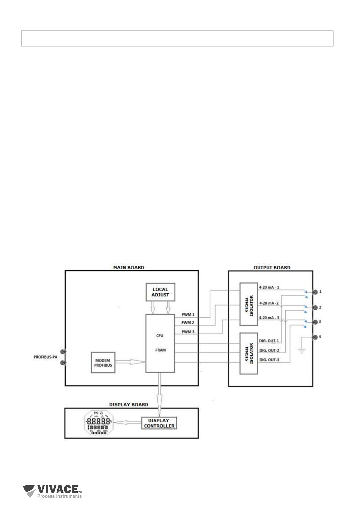
1.1. BLOCK DIAGRAM
The modularization for converter components is described in the following block diagram.
Figure 1.1 – Block diagram for VPO10.

VPO10 PROFIBUS TO ANALOG/DISCRETE OUTPUT CONVERTER INSTALLATION, OPERATION, CONFIGURATION AND MAINTENANCE MANUAL
8
The main board controls the main functions of the converter, the Profibus-PA Modem and the
microcontroller (CPU). The output board receives the CPU signals converted to analog signals (4-20 mA)
via PWM, isolated from the CPU, or the output board receives the converted CPU signals into discrete open
collector digital signals (maximum current 400 mA , 24 Vdc), isolated from the CPU. The main board CPU
performs all the logic of conversion and control of the settings through its firmware.
The CPU also receives the inputs of the local adjustment block (Hall type sensors) for the local
configuration of the converter via magnetic switch.
Modem Profibus block interfaces CPU with Profibus-PA signals of the communication network.
The display board has the controller block that interfaces between the LCD and the CPU, adapting
the messages to be displayed in the display.
VPO10 PROFIBUS TO ANALOG/DISCRETE OUTPUT CONVERTER INSTALLATION, OPERATION, CONFIGURATION AND MAINTENANCE MANUAL
9
2 INSTALLATION
RECOMMENDATION
When taking the equipment to the installation location, transfer it in the original packaging.
Unpack the equipment at the installation location to avoid damage during transportation.
RECOMMENDATION
Model and specification of equipment are indicated on identification plate, located at the top of
the housing. Check if supplied specification and model correspond to application requirements.
STORAGE
The following precautions should be observed when storing the equipment, especially for a
long period:
1) Select a storage area that meets the following conditions:
a) No direct exposition to rain, water, snow or sunlight.
b) No exposition to vibration and shocks.
c)
Normal temperature and humidity (around 20°C / 70°F, 65% RH)
.
However, it can also be stored under the following temperature and humidity intervals:
●Ambient Temperature: -40°C to 85°C (without LCD)* or -30°C to 80°C (with LCD)
●Relative Humidity: 5% to 98% RH (@ 40°C)
(2) For equipment storage, use original factory package (or similar).
(3) If storing an already used Vivace equipment, dry every moist part and clean all
connections that was in contact with the process. Keep covers and connections closed and
properly protected for its specific application and requirements.
* Only for general use. For explosion proof version, follow product certification requirements.

VPO10 PROFIBUS TO ANALOG/DISCRETE OUTPUT CONVERTER INSTALLATION, OPERATION, CONFIGURATION AND MAINTENANCE MANUAL
10
2.1. MECHANICAL ASSEMBLY
VPO10 converter is designed for field installation and therefore supports weather exposure, having
good performance with variations in temperature, humidity and vibration.
Its housing has an IP67 degree of protection, being immune to water entering its electronic circuit
and terminal, provided that the cable gland or conduit of the electrical connection is correctly assembled
and sealed with non-hardenable sealant. The covers should be tightly closed to prevent moisture from
entering because the threads of the housing are not protected by paint.
The electronic circuit is coated with a moisture-proof lacquer, but constant exposures to moisture or
corrosive media can compromise its protection and damage the electronic components.
Figure 2.1 shows the dimensional design and assembly forms of VPO10.
Figure 2.1 – Dimensional drawing and assembly scheme for VPO10.
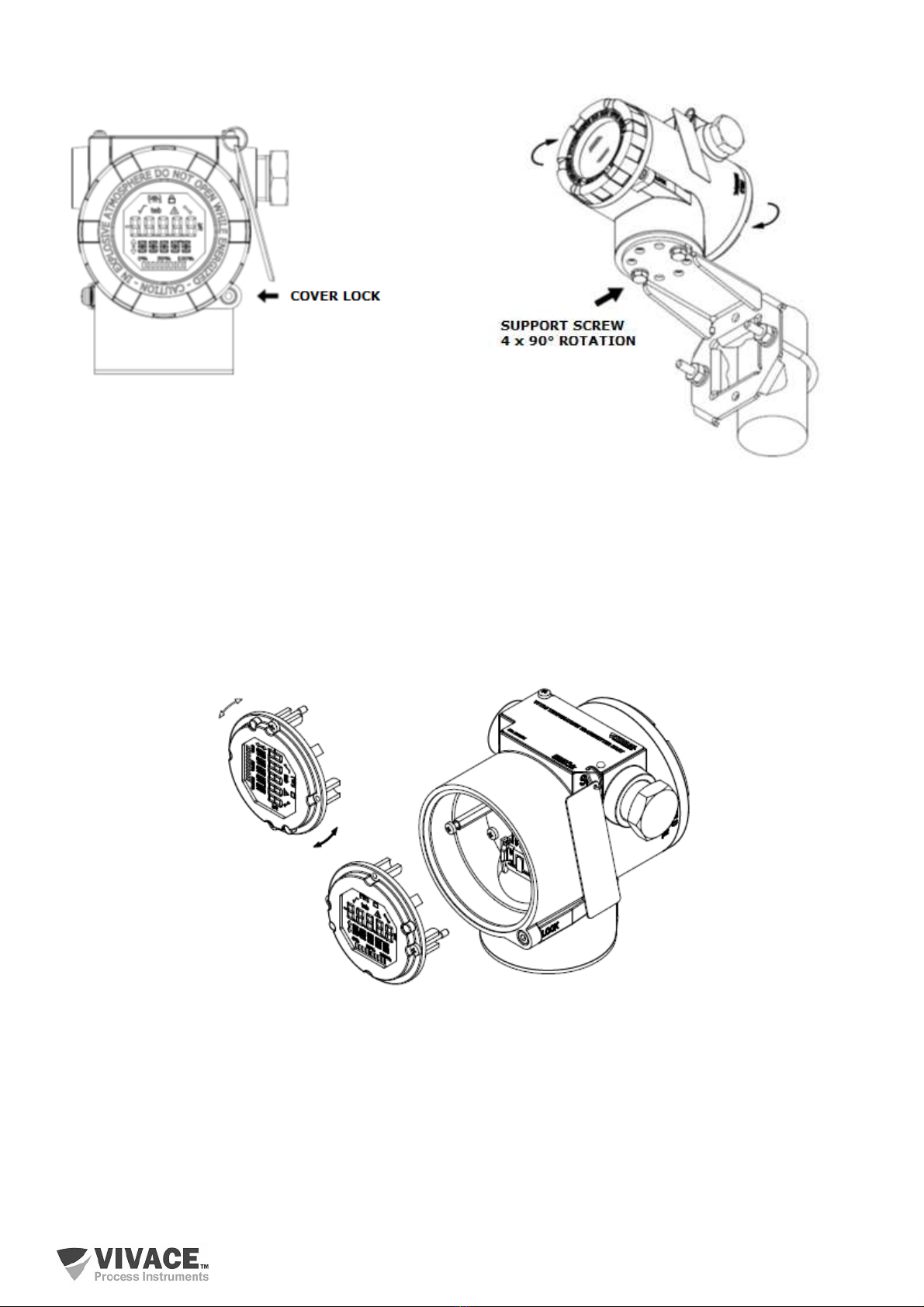
To avoid the risk of involuntary loss of VPO10 covers due to vibration, for instance, it can be locked
by screw, as shown on figure 2.2.
VPO10 is a field device, so it can be installed through a mounting bracket on a 2” tube attached with
a U clip. The converter can also be attached with the same mounting bracket to a wall or panel.
For best LCD positioning device enables 4 x 90° housing rotation, as shown on figure 2.3.
VPO10 PROFIBUS TO ANALOG/DISCRETE OUTPUT CONVERTER INSTALLATION, OPERATION, CONFIGURATION AND MAINTENANCE MANUAL
11
Figure 2.2 – Front cover lock.
Figure 2.3 – Housing positioning.
VPO10 liquid crystal display can be rotate 4 x 90° so indication will be adequate for user visualization.
Figure 2.4 illustrates rotation possibilities for VPO10 LCD.
Figure 2.4 –4 x 90° LCD rotation.
VPO10 PROFIBUS TO ANALOG/DISCRETE OUTPUT CONVERTER INSTALLATION, OPERATION, CONFIGURATION AND MAINTENANCE MANUAL
12
2.2. ELECTRICAL CONNECTION
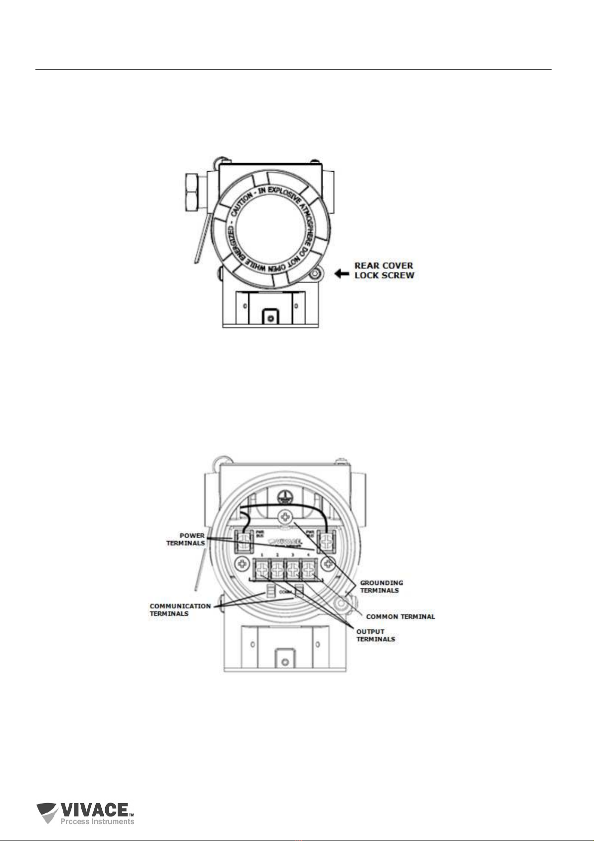
In order to access the terminal block user must remove VPO10 rear cover. First, loose cover lock
screw (see figure 2.5) by turning it clockwise.
Figure 2.5 – Rear cover lock.
Figure 2.6 shows the power terminals (PWR BUS) and the connection terminals of the VPO10
conversion outputs, in addition to ground terminals (one internal and one external) and communication
terminals. To power the equipment it is recommended to use Profibus-PA type AWG18 certified cables with
shield (capacitance < 30 pF).
Figure 2.6 – Connections and terminal description for VPO10.
VPO10 PROFIBUS TO ANALOG/DISCRETE OUTPUT CONVERTER INSTALLATION, OPERATION, CONFIGURATION AND MAINTENANCE MANUAL
13
Table 2.1 shows terminal description for VPO10.
Table 2.1 – Terminal description for VPO10.
NOT
E
All cables used for connecting VPO10 with PROFIBUS-PA network must be shielded to avoid
interference or noise.
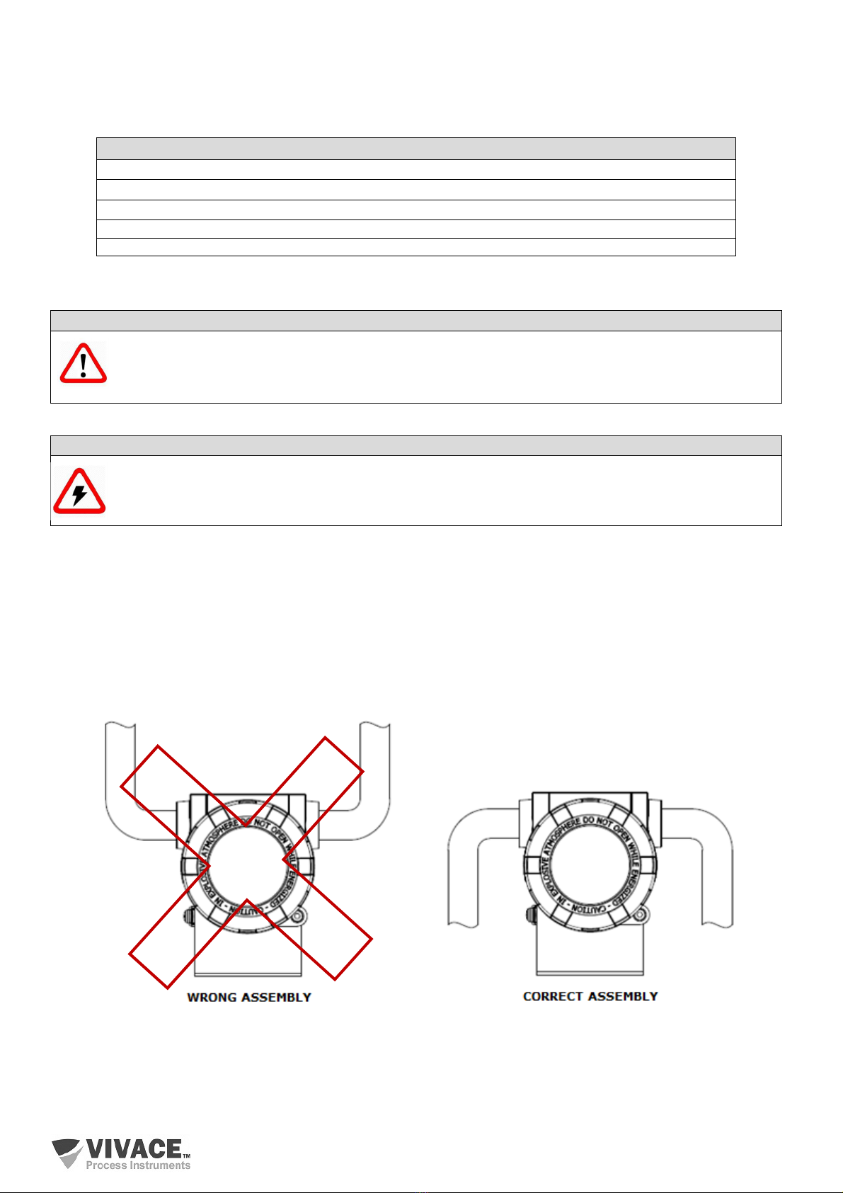
Conduits used for power cables must be assembled in order to avoid water entrance in the device
terminal block. Conduit screws must be sealed according to specific area required standards.
Non-used electrical connection must be sealed with appropriate cover.
Figure 2.7 shows the correct installation for conduit, in order to avoid the entrance of water or any
corrosive material that may cause damage to the device.
Figure 2.7 – Conduit assembly.
Terminal Description
Power Terminals
-
PWR BUS 9
-
32 Vdc not polarized
Grounding Terminals
-
1 internal and 1 external
Communication Terminals
–
PROFIBUS
-
PA communication with configurator
Terminals 1, 2 and 3 – Current (4-20 mA) or discrete outputs, configurable
Terminal – 4 – Common – Negative of Power Supply
NOTE
It is extremely important to ground the equipment for complete eletromagnetic protection and
also to ensure the correct performance of transmitter on Profibus-PA network.
VPO10 PROFIBUS TO ANALOG/DISCRETE OUTPUT CONVERTER INSTALLATION, OPERATION, CONFIGURATION AND MAINTENANCE MANUAL
14
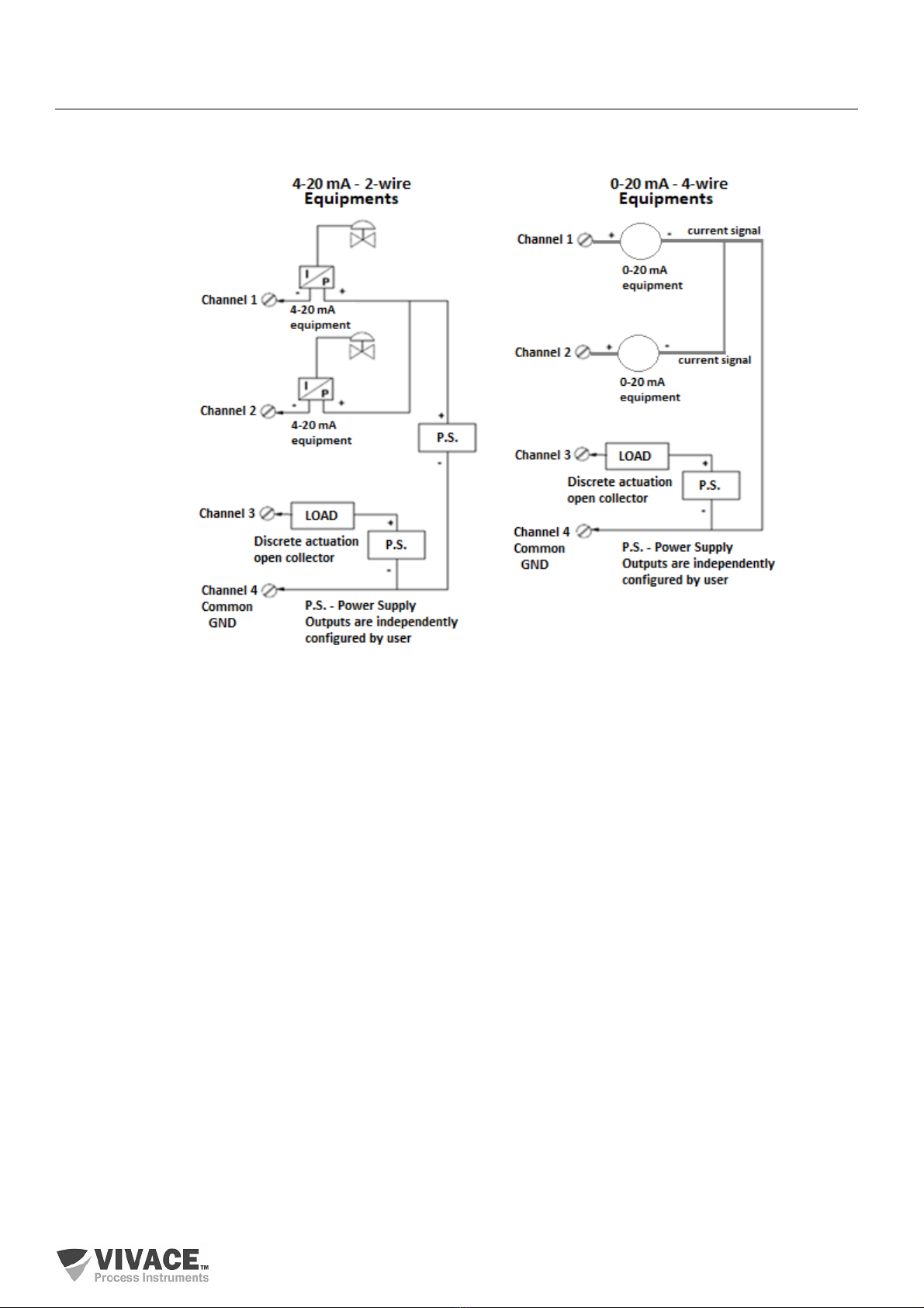
2.3. PROCESS CONNECTION
The following are possible connections of VPO10 in the process:
Figure 2.8 – Process connection example for VPO10.
VPO10 PROFIBUS TO ANALOG/DISCRETE OUTPUT CONVERTER INSTALLATION, OPERATION, CONFIGURATION AND MAINTENANCE MANUAL
15
2.4. PROFIBUS-PA NETWORK CONNECTION
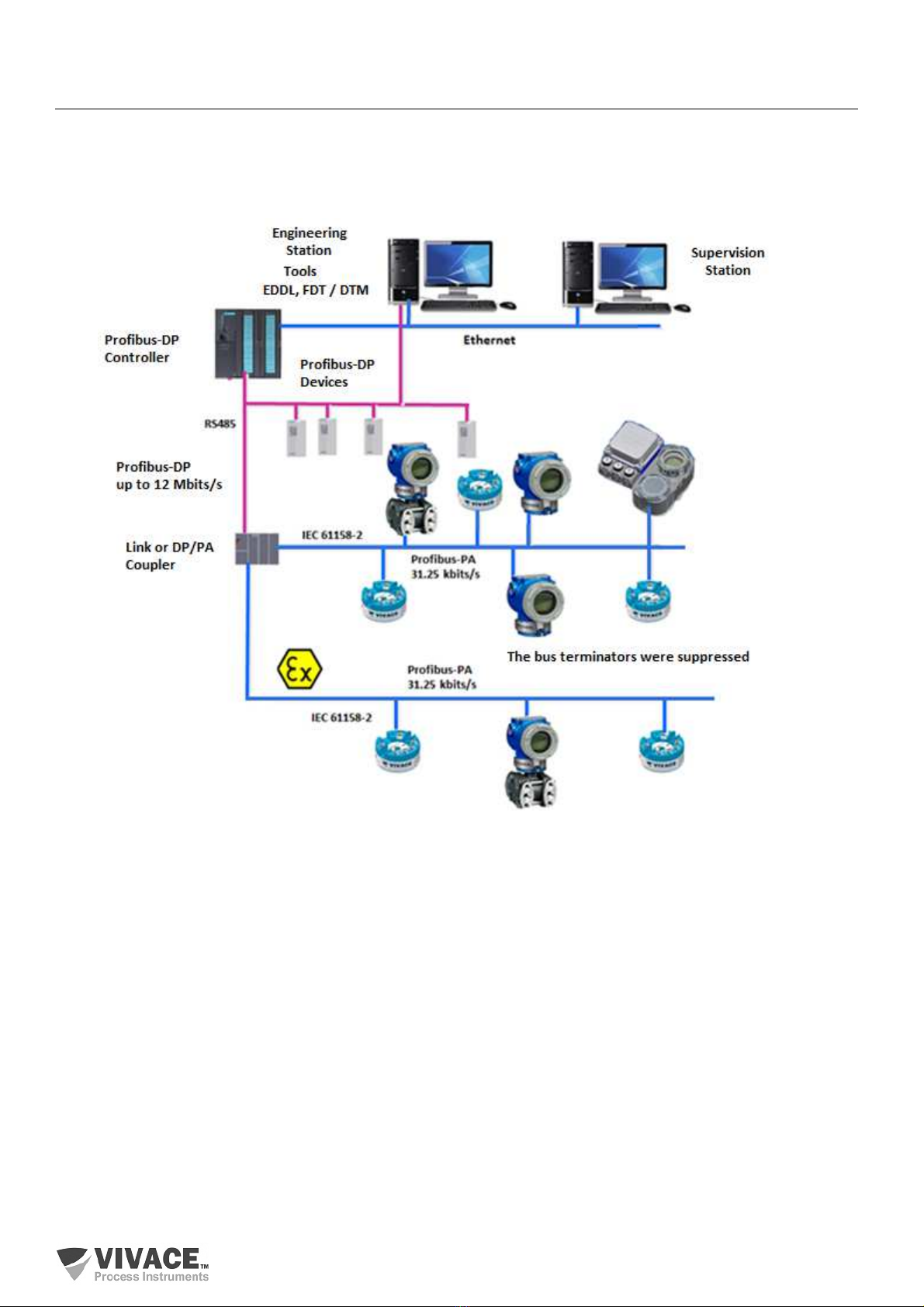
Figure 2.9 illustrates the installation of a number of Profibus network elements and the
connection of Profibus-PA devices to the Profibus network.
Figure 2.9 – Connecting a Profibus-PA device to the bus.
VPO10 PROFIBUS TO ANALOG/DISCRETE OUTPUT CONVERTER INSTALLATION, OPERATION, CONFIGURATION AND MAINTENANCE MANUAL
16
3 CONFIGURATION
The configuration of VPO10 can be done through a programmer compatible with Profibus-PA
technology. Vivace offers the interfaces of VCI10-P line (USB,and Bluetooth) as a solution for configuration
and monitoring of the Profibus-PA line equipment. User can also configure the VPO10 by local adjustment
using a Vivace magnetic key.
3.1. LOCAL CONFIGURATION
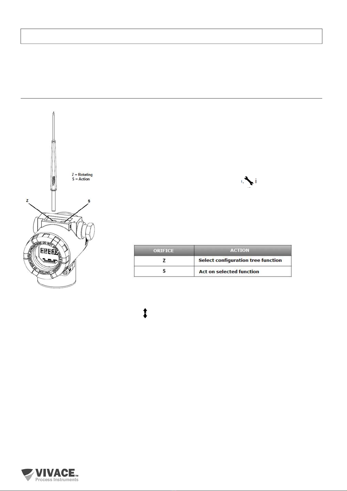
Equipment’s local configuration is executed by using Vivace’s magnetic
screwdriver on Z and S orifices, located at housing superior side, under
identification plate. Orifice Z starts local configuration and changes the field to
be configured. Orifice S is responsible for changing and saving the new value
on the selected field. Saving after LCD value changing is automatic.
Figure 3.1 shows orifices Z and S for local configuration, stamped on device
housing, and their functions on magnetic screwdriver actuation.
Insert the magnetic screwdriver on Zero orifice (Z). icon appears to indicate
that device has recognized the screwdriver action. Keep the magnetic
screwdriver inside until “LOCAL ADJST” message is shown on display, and
then remove it for 3 seconds. Insert the magnetic screwdriver into Z orifice
again, so user can navigate through local adjust parameters.
Table 3.1 indicates actions executed by magnetic screwdriver when inserted
on Z and S orifices.
Table 3.1 – Z and S orifices actions.
Figure 3.1 – Z and S orifices and magnetic screwdriver.
Some parameters show the icon to allow user configuration on it by inserting the magnetic
screwdriver into Span orifice (S). In case the parameter has pre-defined values, those will be rotate on
display, while the magnetic screwdriver remains into Span orifice (S).
If the parameter is numerical, this field will enter on edition mode and decimal point will start blinking,
and shifting to left. When user removes magnetic screwdriver from S, the least significant digit (in the right)
starts blinking, indicating it is ready for edition. By inserting the magnetic screwdriver into S, user is enabled
to increase the digit value, from 0 to 9.
After the least significant digit edition, user should remove magnetic screwdriver from S in order to
start the edition of the next digit (in the left). User will be able to edit each digit independently, until the most
significant digit (5th digit on the left) is complete. After the 5th digit edition, user can also change the signal
for the numerical value still on S orifice.
During each step of edition, user is able to return to the previous digit (to the right) by inserting the
magnetic screwdriver into Z orifice, so corrections can be made. By removing the magnetic screwdriver at
any time, user will see the digits blinking until the final step, where the edition mode will be finished, saving
the numerical value configured by user.
VPO10 PROFIBUS TO ANALOG/DISCRETE OUTPUT CONVERTER INSTALLATION, OPERATION, CONFIGURATION AND MAINTENANCE MANUAL
17
If the configured value is not acceptable by that device parameter (invalid value), it will be returned
to the last valid value before edition. Depending on the parameter, some values can be shown on numerical
or alphanumerical fields, adjusting the best option view to user.
With the magnetic screwdriver out of Z and S orifices, device will leave local adjust mode after some
seconds and monitoring mode will be shown.
3.2. JUMPER CONFIGURATION FOR LOCAL ADJUST AND WRITE PROTECTION
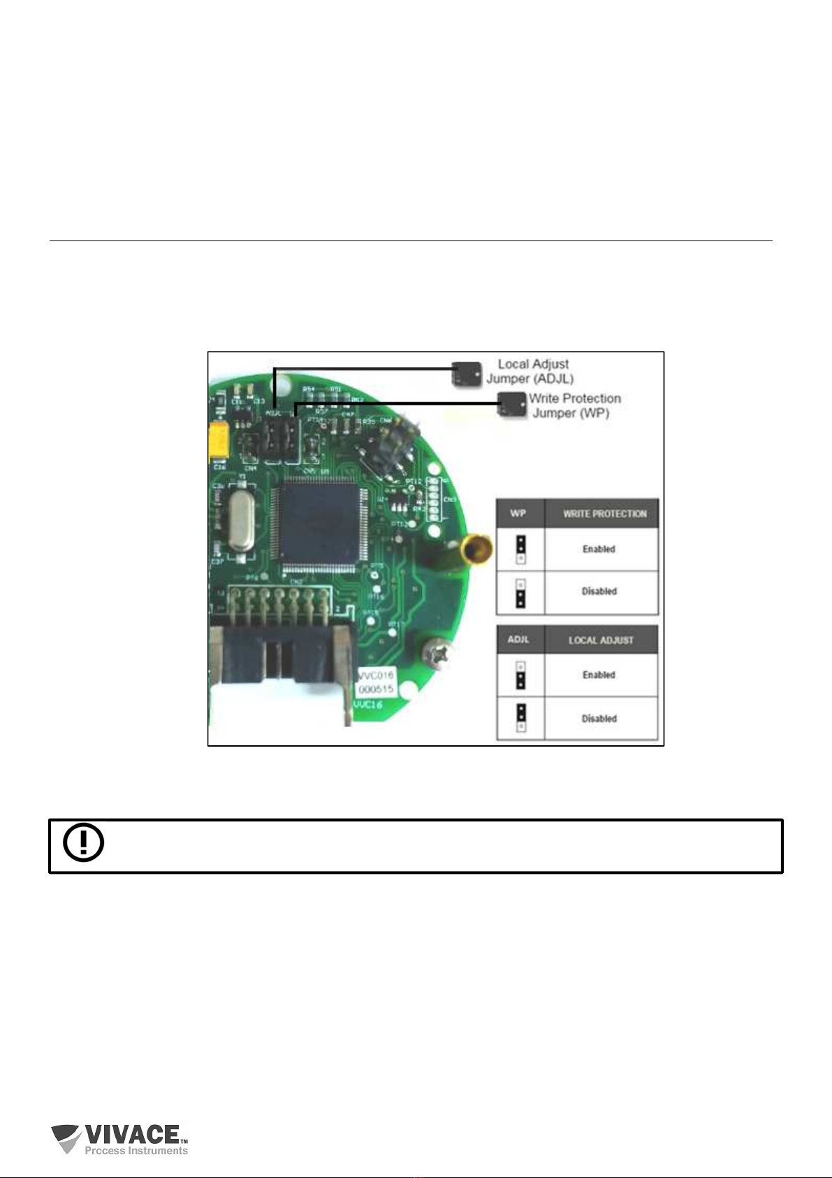
VPO10 has two jumpers on its main board to protect data writing (WP) and enabling/disabling local
adjust (ADJL). Figure 3.2 presents those jumpers.
Figure 3.2 – Jumpers WP (write protection) and ADJL (local adjust) on VPO10 main board.
Default selection for these jumpers is Write Protection DISABLED and Local Adjust ENABLED
.
VPO10 PROFIBUS TO ANALOG/DISCRETE OUTPUT CONVERTER INSTALLATION, OPERATION, CONFIGURATION AND MAINTENANCE MANUAL
18
3.3. LIQUID CRYSTAL DISPLAY (LCD)
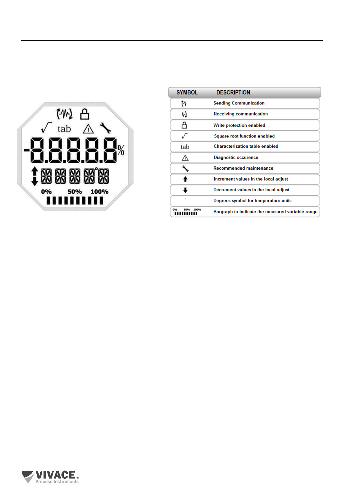
Main information related to converter are indicated on its liquid crystal display (LCD). Figure 3.3
shows the LCD with all its indication fields. Numerical field has 5 digits and is used mainly for monitored
variable indication. Alphanumerical field indicates which variable is being monitored, units or auxiliary
messages. Each indication icon use is described on table 3.2.
Figure 3.3 – LCD fields and icons. Table 3.2 – LCD icon description
3.4. LOCAL ADJUST CONFIGURATION TREE
Figure 3.4 shows available fields for local configuration and the sequence they are presented by
magnetic screwdriver actuation on Z and S orifices.
ADDR – In this menu, the address of the equipment in the PA network is configured. Address 126
is the default value (factory default). User can configure the slave address from 0 to 126, usually master
devices in Profibus-PA network are configured with addresses 0, 1 and 2, so we recommend configuring
slave devices between 3 and 125.
GSDId – Here the "GSD Identification Number" is set as Profile Specific or Manufacturer Specific
(factory default).
CHNL1, 2 e 3 – Here user can configure the units for channels 1, 2 and 3: Current or Voltage.
LCD1, 2 e 3 – Here user can configure what will be displayed on LCD1, 2 and 3: PV_1, PV_2, PV_3,
OUT_1, OUT_2 or OUT_3.

VPO10 PROFIBUS TO ANALOG/DISCRETE OUTPUT CONVERTER INSTALLATION, OPERATION, CONFIGURATION AND MAINTENANCE MANUAL
19
Figure 3.4 – Local adjustment programming tree for VPO10.
3.5. PROFIBUS PROGRAMMER
The configuration of the equipment can be done using a Profibus-PA compatible programmer.
Vivace offers the interfaces of VCI10-P (USB and Bluetooth) line as a solution for identification,
configuration and monitoring of Profibus-PA line equipment.
Figure 3.5 shows the wiring diagram for configuring VPO10 using Vivace VCI10-UP USB
interface, which feeds the device in local mode, with a personal computer that has PACTware
configurator software.
Figure 3.5 – Configuration diagram of VPO10 with VCI10-UP.
VPO10 PROFIBUS TO ANALOG/DISCRETE OUTPUT CONVERTER INSTALLATION, OPERATION, CONFIGURATION AND MAINTENANCE MANUAL
20
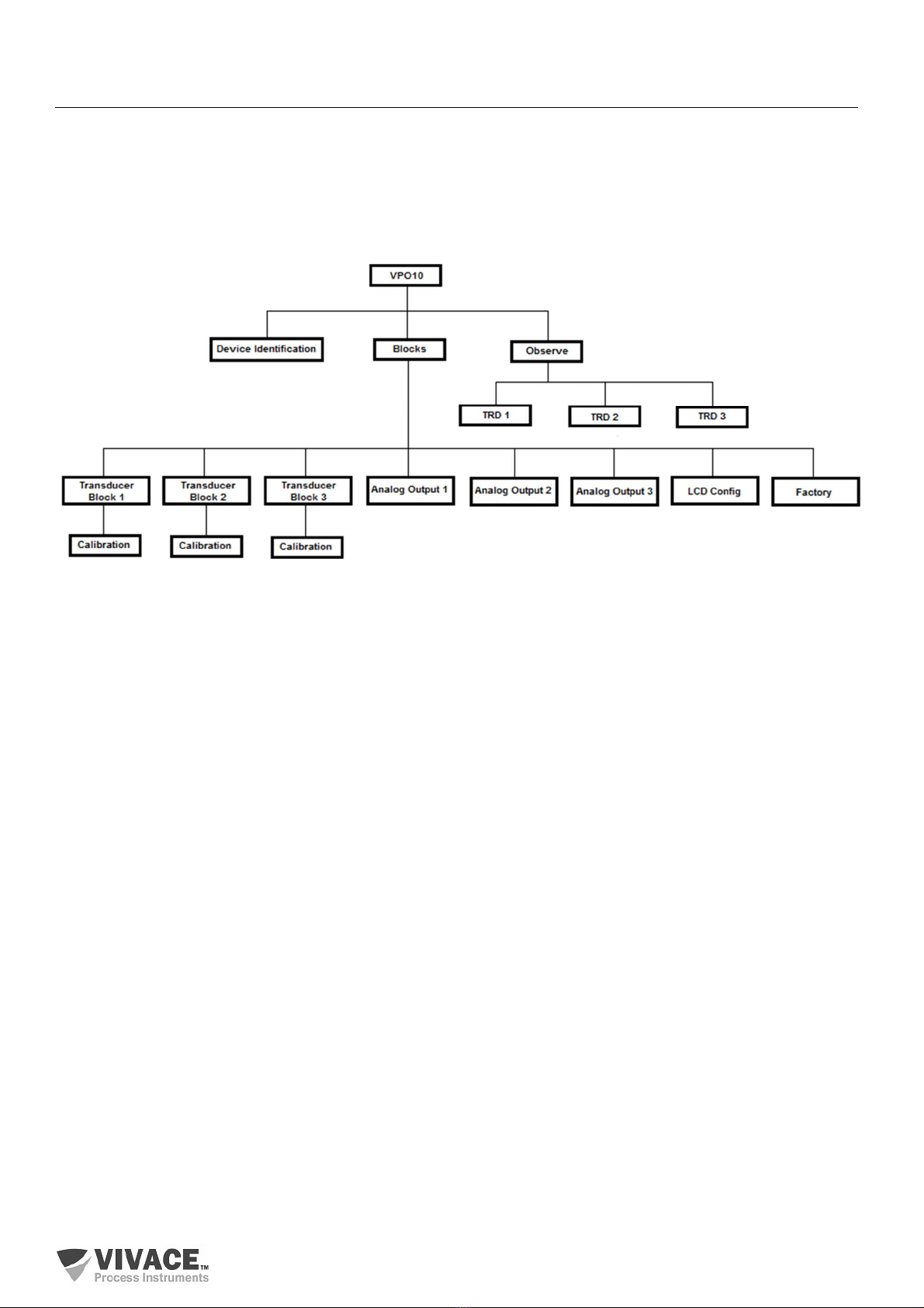
3. . PROFIBUS-PA CONFIGURATOR PROGRAMMING TREE
The programming tree is a tree-shaped structure with a menu of all available software features, as
shown in Figure 3.6
To configure converter online make sure that it is properly installed, with the proper power supply
voltage, required for communication.
Figure 3.6 – Programming tree for VPO10.
Device Identification - In this menu (Physical Block) the main information about the equipment can be
accessed, such as: Tag, Manufacturer ID, Device ID, Order Code and Firmware Version.
Transducer Block 1/2/3 - Here transducer block 1, 2 or 3 is configured, respectively.
• Basic Settings - In this menu user can configure the output (discrete output or current output), the
measurement scale (EU0% and EU100%) and configure SP rates and limits.
• Relay - Here user can select the relay (Low, High or Deviation), its value and hysteresis.
oCalibration - In this menu the lower and upper adjustment of the variable is executed.
Analog Output 1/2/3 - Here the parameters of output blocks 1, 2 and 3 are configured respectively.
• Basic Settings - In this menu user can configure the PV Scale (EU0%, EU100%), the Input Unit (% or
mA), the Output Scale (EU0% and EU100%), (% or mA).
• Mode Block - In this menu the Setpoint is configured as follows:
oMan - In this option the Target parameter must be set to Manual and user can set the value of
the setpoint to the output (OUTPUT MAN).
oSetpoint - In this option the Target menu must be set to Automatic and user can set the Setpoint
from Operator value.
oRemote - In this option the Target menu must be in Rcas (Remote Cascade) and the Setpoint
value will come from the remote controller.
• Fail Safe - This menu configures the Safe Position, Last Setpoint or Safe Value, Fault Safety Value
and Fault Safety Time.
• Return from TRD Blk - This parameter monitors the return value of the transducer block, the position
of the discrete control valve and the deviation value of the setpoint.
• Simulate - This menu enables or disables the Simulation function. With the menu enabled, user can
manually set the transducer value and the status.
Table of contents
Other Vivace Media Converter manuals


