Vivaldi V Series User manual


VivaldiCopyright2012©V1.0 2
Table of contents
INTRODUCTION............................................................................................................................................. 3
VIVALDI PUMPS - TECHNICAL FEATURES................................................................................................ 4
CONCERTORANGESERIESV4
Explodedviewofallmodels..................................................................................................................................5
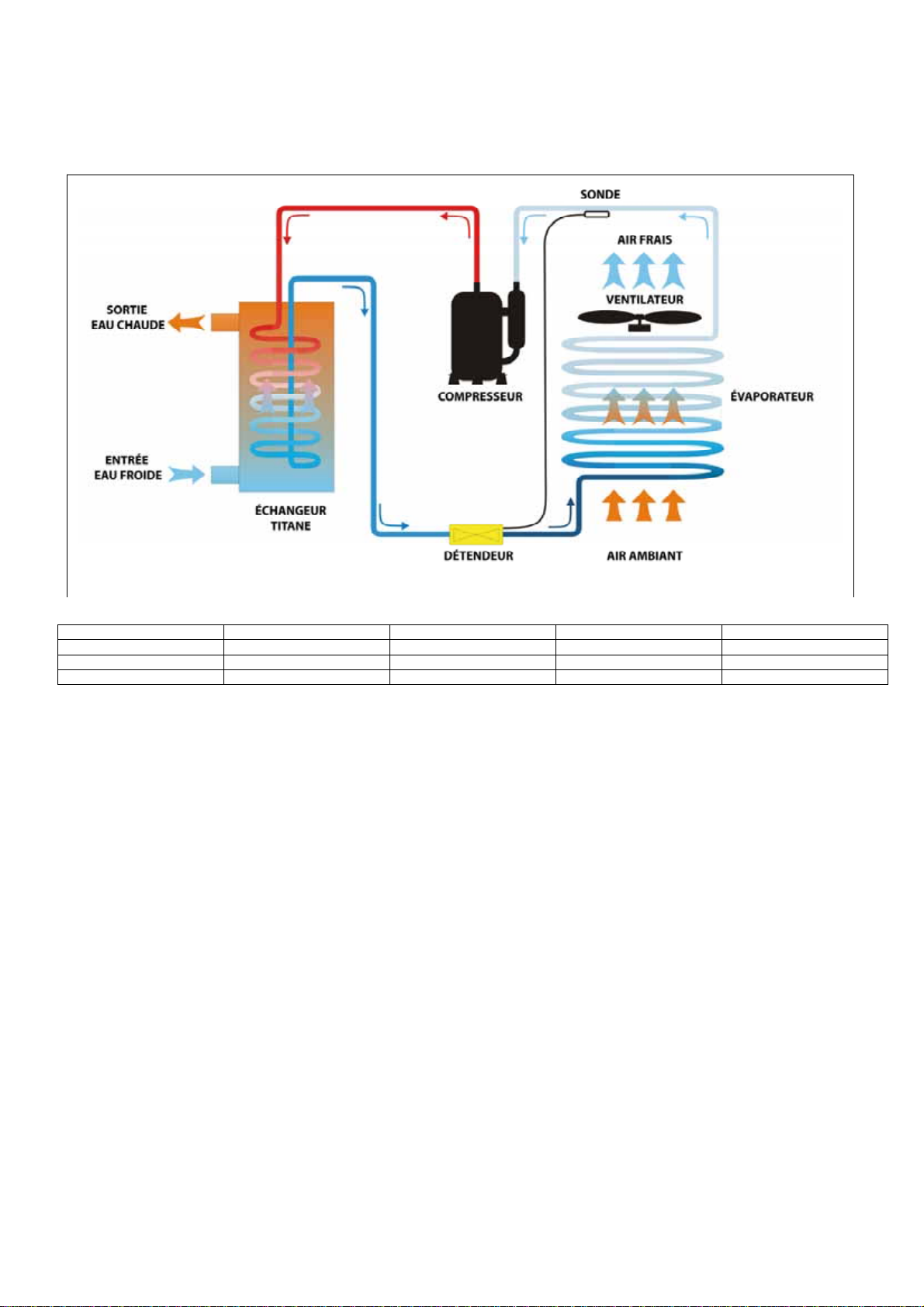
GENERAL DIAGRAM OF THE HEATING AND COOLING CIRCUIT........................................................... 6
Heatingmode .......................................................................................................................................................6
Coolingmode ........................................................................................................................................................6
CONTROL AND SAFETY SYSTEM............................................................................................................... 7
3controldevices ...................................................................................................................................................7
4safetysystems....................................................................................................................................................7
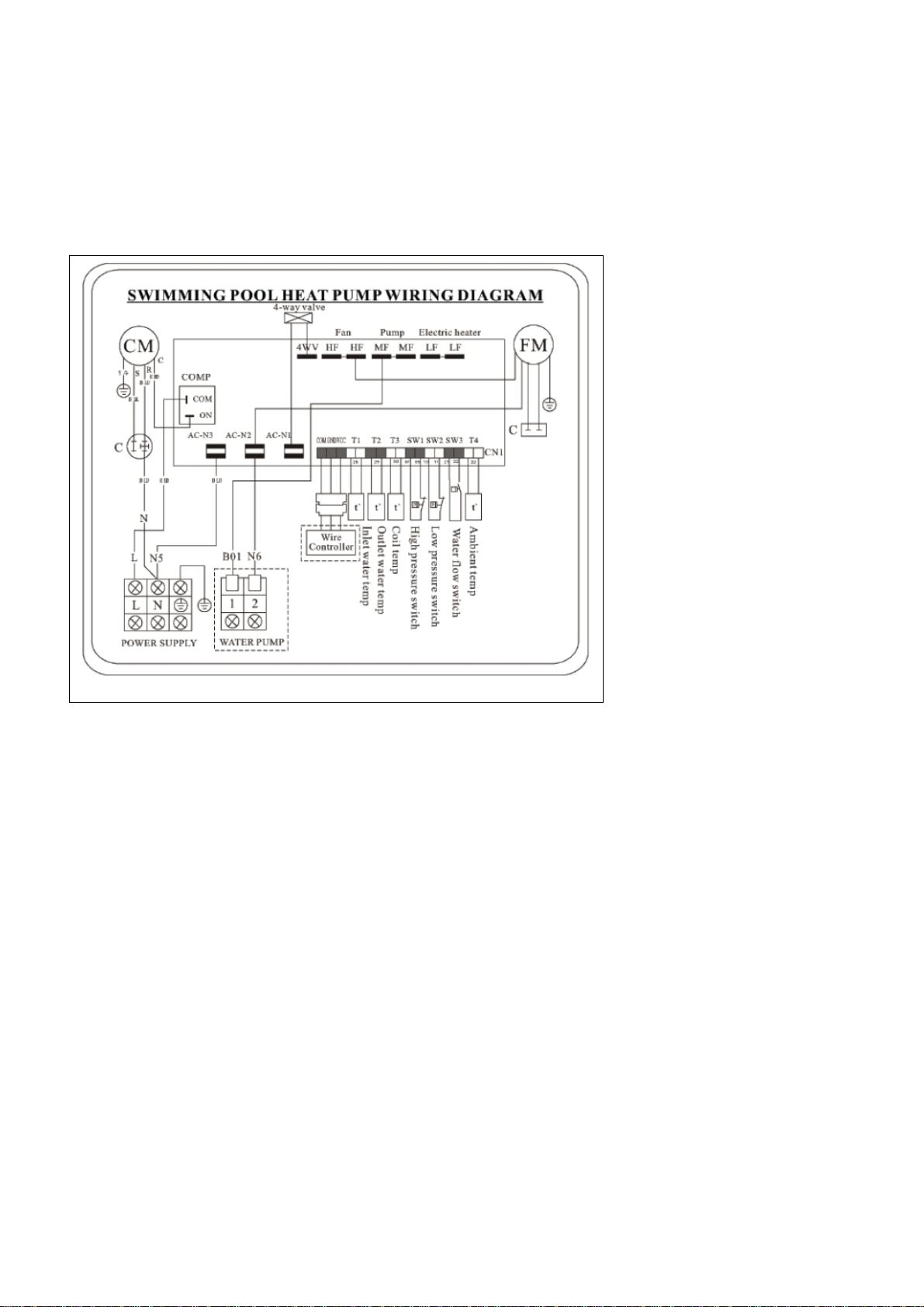
DIAGRAMS OF THE ELECTRONIC CARDS ................................................................................................ 8
Concertorange–V30,V40,V50,V60,V70 ......................................................................................................8
HEAT PUMP INSTALLATION RULES.......................................................................................................... 9
Minimumdistancefromobstacles:.......................................................................................................................9
Distancerequiredfromthepool ...........................................................................................................................9
Otherinstallationprecautions ............................................................................................................................10
ElectricalstandardC15‐100section702.............................................................................................................10
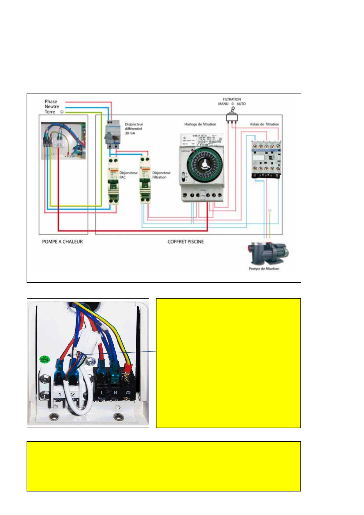
ELECTRICAL INSTALLATION ....................................................................................................................11
Filterpumpservocontrol ....................................................................................................................................12
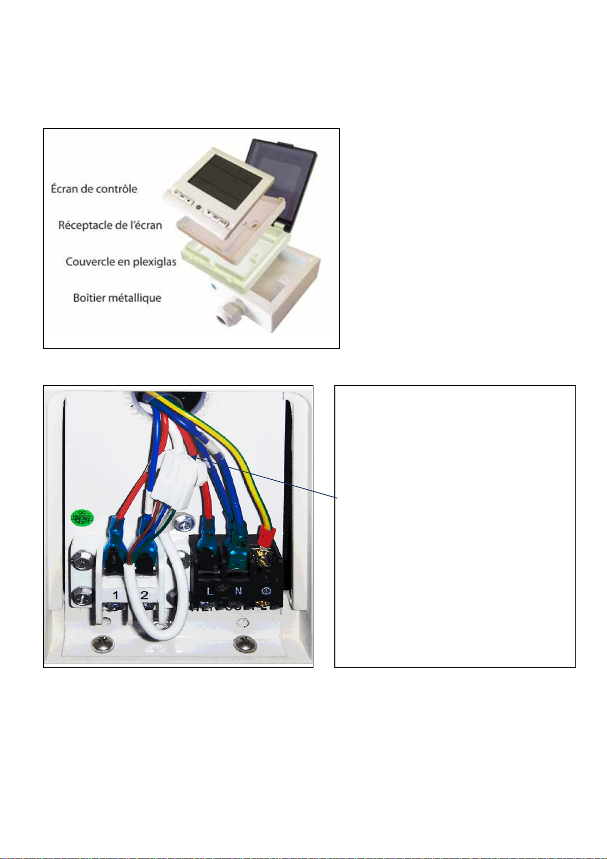
Assemblyandinstallationofthecontrolbox......................................................................................................13
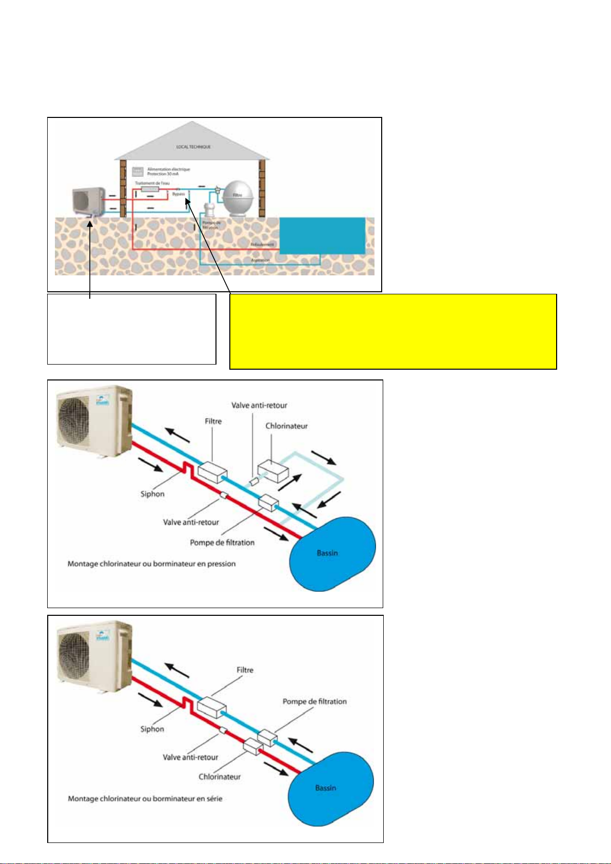
–HYDRAULIC INSTALLATION.................................................................................................................... 13
EXAMPLESOFCONNECTIONS14
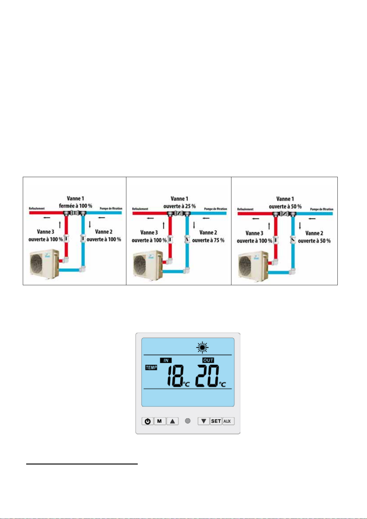
Bypass(divertervalves) ......................................................................................................................................15
INITIAL COMMISSIONING........................................................................................................................... 16
Calculatethetemperatureincreasetime ...........................................................................................................16
Operatingprinciple .............................................................................................................................................17
SafetyInstructions ..............................................................................................................................................17
Recommendedoperatingtemperature ..............................................................................................................17
Operationduringcoldseasons ...........................................................................................................................17
Defrostcycles ......................................................................................................................................................17
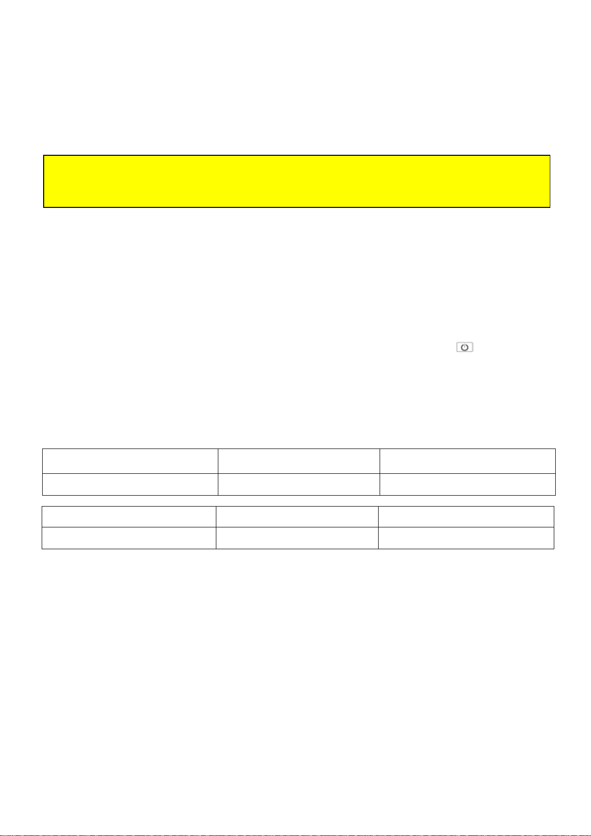
Descriptionofthecontrolpanel..........................................................................................................................18
Selectmode.........................................................................................................................................................18
Configurationoftheheatpump .........................................................................................................................19
Errormessages/Errorfixing(1):.........................................................................................................................20
Errormessages/Errorfixing(2):.........................................................................................................................21
Errormessages/Errorfixing(3):.........................................................................................................................22
Tableoferrorcodesandcorrectiveaction..........................................................................................................23
GENERAL MAINTENANCE .........................................................................................................................25
Cleaningthefilterandthebasket.......................................................................................................................25
Adjustmentofthebypassvalves.........................................................................................................................25
Controlofwaterchemistry .................................................................................................................................25
Recommendedwaterchemistryvalues ..............................................................................................................25
Wintering ..............................................................................................................................................................1
Cleaningtheevaporator .....................................................................................................................................25
Removinglimescale ............................................................................................................................................25
GUARANTEE................................................................................................................................................26
Durationandpurposeoftheguarantee .............................................................................................................26
LimitsoftheGuarantee ......................................................................................................................................26
Repairsunderguarantee ....................................................................................................................................26
DECLARATION OF EC CONFORMITY....................................................................................................... 28

VivaldiCopyright2012©V1.0 3
Introduction
Congratulations for choosing the reversible Vivaldi heat pump for your pool!
This equipment has been installed in accordance with current standards and is now ready for use.
Carefully read through this documentation to ensure that you know all its rules of operation.
For your satisfaction we provide the following details:
The heat pump does not heat the water in the pool if the filter pump is running.
At the start of the season or when the outside temperature is low, you should increase the daily filtration time
so that the heat pump can compensate for the higher heat losses from the pool.
The use of a heated cover such as a bubble cover is highly recommended.
Please read the whole of this brochure. If necessary, ask your installer to explain anything you do not understand.
This manual is a full part of the product and should therefore be continually available in your technical room.
The heat pump is designed exclusively for heating and cooling swimming pools. Any other unspecified or non-
compliant use shall be considered dangerous and inappropriate
Pump assembly, wiring and commissioning must be carried out by a qualified professional.
You must ensure that the temperature of the water in the pool is lower than that recommended by the pool
manufacturer. In the interest of continuous improvement, our products are subject to change without notice.
The photos in this brochure or features described are not contractually binding.
Any failure or error message, even accidental, must be reported to your dealer/installer;
Ensure that maintenance is carried out by a qualified professional.
Furthermore, to protect your investment, we strongly advise you to take out a maintenance contract for the upkeep of
your heat pump. Contact your installer or "pool engineer" for more information
We hope you enjoy bathing in comfortable temperatures for many seasons.

VivaldiCopyright2012©V1.0 4
Monitoring the delivery
When the pump is delivered, check the condition of the packaging. If there is any damage, inform the carrier within 48
hours by registered mail, with acknowledgement of receipt.
Before handling, carry a full inspection of the machine.
Vivaldi Pumps - technical features
Concerto Range Series V
Concerto
Features Units V 30 V 40 V 50 V 60 V 70
Pool volume ( Ambient air temperature 5°C ) m3 Up to 30 20 - 40 30 - 50 40 - 60 50 - 75
Heating capacity ( Air 24 ° C/Water 27 ° C) kW 4.5 5.3 7.8 9.5 12.3
Power consumption kW 0.84 1.01 1.50 1.83 2.36
Rated current A 3.8 5 6.8 8.3 10.7
(COP) 5.35 5.2 5.2 5.2 5.2
Heating capacity ( Air 15 ° C/Water 26 ° C) kW 3.7 4.6 6.4 7.7 9.0
Power consumption kW 0.86 1.02 1.45 1.8 2.09
Rated current A 3.9 5.4 6.9 8.2 9.0
(COP) 4.3 4.5 4.4 4.3 4.3
Cooling capacity (Air35 ° C/Water 27 ° C) kW 3.5 4.5 6.2 7.5 8.8
Power consumption kW 0.92 1.18 1.63 1.97 2.26
Rated current A 4.2 5.4 7.4 8.9 10.3
EER 3.8 3.8 3.8 3.8 3.9
Air expulsion direction Horizontal Horizontal Horizontal Horizontal Horizontal
Cover type Plastic Plastic Plastic Plastic Plastic
Sound level at 1 metre dB(A) 50 50 51 51 52
Electrical characteristics V / Ph / Hz 230 / 1 / 50 230 / 1 / 50 230 / 1 / 50 230 / 1 / 50 230 / 1 / 50
Maximum heat intensity A 5.8 7.6 10.3 12.5 14.4
Operating temperature Celsius +5° to +35° +5° to +35° +5° to +35° +5° to +35° +5° to +35°
Compressor brand Hitachi Hitachi Hitachi Hitachi Hitachi
Compressor type Rotatory Rotatory Rotatory Rotatory Rotatory
Gas type/Pressure Type / kg R 410A/ 0.55 R 410A/ 0.7 R 410A/ 1.1 R 410A/ 1.3 R 410A/ 1.5
Gauge Yes Yes Yes Yes Yes
Number of fans 1 1 1 1 1
Water flow Min - Max
(m3/h) 3/-5 3.5/-5 5/-7 5/-7 5/-7
Diameter of water connections Millimetres 50 50 50 50 50
Composition of the heat exchanger Titanium/PV
C Titanium/PV
C Titanium/PV
C Titanium/PV
C Titanium/PV
C
Hydraulic switch Yes Yes Yes Yes Yes
Control panel LCD LCD LCD LCD LCD
Auto defrost Yes Yes Yes Yes Yes
Remote control Yes Yes Yes Yes Yes
Filter pump servo control Yes Yes Yes Yes Yes
Packaging measurements L x W x H
(mm) 960 / 380 / 680 960 / 380 / 680 960 / 380 / 680 960 / 380 / 680 960 / 380 / 680
Pump measurements L x W x H
(mm) 890 / 370 / 640 890 / 370 / 640 890 / 370 / 640 890 / 370 / 640 890 / 370 / 640
Net weight/packaged weight Kg 42/47 44/49 52/57 55/60 59/65

VivaldiCopyright2012©V1.0 5
Vivaldi Pumps - technical features
Exploded view of all models

VivaldiCopyright2012©V1.0 6
General diagram of the heating and cooling circuit
The heat pump is reversible. It can either heat or cool the pool water.
Hot water outlet Compressor Sensor
Cold water inlet Fresh air Evaporator
Titanium heat exchanger Pressure regulator Fan
Ambient air
Heating mode
The liquid refrigerant absorbs heat from the air through the evaporator (the blade radiator) in which it is vaporised.
Then it is pressurised and heated by the compressor which sends it to the condenser (heat exchanger), where it
releases the heat (by transferring it to the pool water) and then returns to liquid state. It loses its pressure and
continues to cool in the expansion capillaries before returning to the evaporator and starting a new cycle.
Cooling mode
The 4-way valve reverses the flow of the liquid refrigerant. The fluid evaporates in the heat exchanger (evaporator) by
recovering the heat contained in water and then passes through the compressor which heats it. It then passes
through the blade radiator (which becomes a condenser) and returns to the liquid state.

VivaldiCopyright2012©V1.0 7
Control and safety system
3 control devices
1. An evaporator temperature sensor enables the automatic defrost to start.
2. An ambient temperature sensor manages pump shut-down when the outside air temperature no longer
enables normal heat pump operation.
3. A temperature sensor on the heat exchanger ensures that heating stops when the desired temperature is
achieved. The normal cycle resumes when the exchanger temperature drops 2 ° C below the required
temperature.
4 safety systems
1. A flow sensor on the heat exchanger
2. A high-pressure short circuit breaker and a low pressure short circuit breaker.
3. A compressor temperature sensor
4. A short circuit magnetic current meter on the compressor, integrated into the electronic card.
If a fault occurs on one of these devices (system failure, power off, abnormal measurements) an error message
appears on the display. See paragraph "Error messages/error fixing"
IMPORTANT!
Any control or safety system alteration or deactivation may cause serious injury or death.

VivaldiCopyright2012©V1.0 8
Diagrams of the electronic cards
Concerto range – V 30, V 40, V 50, V 60, V 70

VivaldiCopyright2012©V1.0 9
Heat pump installation rules
The electrical and hydraulic connections must conform to current standards (NF C 15 100, EC 364 I).
The pump must be installed outdoors. It must be positioned on its own anti-vibration support (silent block), on a flat
heavy base, such as a concrete slab or a rigid robust frame. This support must be sufficiently thick to prevent water
ingress from beneath the pump. The adjustment height must consider the condensate collector.
Minimum distance from obstacles:
During installation, observe the minimum distances from obstacles such as walls or shrubs, as indicated in the
diagram below.
[PAC = Heat Pump]
Do not install the pump in a confined area. The fan would recycle the same air and pump performance would
deteriorate.
The fan should not blow towards windows or passage ways.
Distance required from the pool
The safe distance between the heat pump and the water source (pool, foot bath) must comply with electrical standard
C15-100 section 702. The pump must be installed in Volume 2, i.e. at a minimum distance of 2 metres from the
pool or footbath, horizontally, and a minimum of 2.5 metres, vertically.
––
p
A
C
2.00m0.50m
0.50m
0.50m
AirexpulsionsideAirsuctionside

VivaldiCopyright2012©V1.0 10
[Bassin o pediluve = Pool or footbath]
Other installation precautions
Do not install the pump near a traffic lane to avoid it being spattered by mud.
Do not direct the blowing from the pump in the direction of the prevailing wind.
If the pump is intended for use in winter, set up protection against rain or snow (canopy).
The pump must be in a visible location so that adults can supervise children.
Electrical standard C15-100 section 702
Volumes
- Volume “0”: includes the inside of the pool and the areas with the essential openings (steps) in the walls or the
bottom that can be accessed by people in the pool.
- Volume “1”: is bounded first by the vertical surface 2 m from the edge of the pool and, secondly, by the ground (or
any other surface) where people can stand and the horizontal plane at 2.50 m above the ground. If the pool has diving
boards, starting blocks etc., volume "1" includes the volume bounded by the vertical surface 1.50 m around the
starting blocks and diving boards, and the horizontal plane 2.50 m above the uppermost surface where there may be
people.
- Volume “2”: is bounded first by the outer vertical surface of volume "1" and the parallel surface 1.50 m from the first
and, secondly, by the ground or other surface where people may stand and the horizontal plane at 2.50 m above the
ground or surface.
Selection and implementation of electrical devices
The term "devices" includes electrical outlets, switches, boxes and the devices used to carry out all the wiring. The
term "appliances" means the pool equipment, floodlights, pumps, lighting facilities.
Volume “0”
- No device or appliance use is accepted in volume "0" unless it runs in Safety Extra Low Voltage (SELV) - i.e. 12 volts
AC or 30 volts DC. 300 volts/12 watt pool floodlights are therefore permitted. In this case, the safety source (the
transformer) will obviously be outside volumes "0", "1" and "2".
Volume “1”
- No device is allowed in volume "1", unless it is supplied by SELV. An outlet protected by a 30 mA RCD is accepted
1.25 m from the pool.
- No appliance is allowed in volume "1", unless it is supplied by SELV.
Volume “2”
- Devices are allowed in volume "2", on condition either that they are supplied by SELV or that they are protected by a
30 mA RCD or that they are supplied by an isolating transformer.

VivaldiCopyright2012©V1.0 11
Electrical Installation
The heat pump's circuit should preferably be supplied by an exclusive circuit. The power supply characteristics must
be appropriate to the operation of the material in terms of voltage and frequency. Characteristics: 230 V +/- 10%
single phase current 50 Hz or 380 V +/- 10% three-phase 50 Hz
Any installation must be performed by a qualified electrician in accordance with local rules for electrical supply and
wiring standards. The main switch must be a bipolar cut switch and must be used with a device for short-circuit
current protection device at a leakage current <30 mA.
The heat pump circuit must be connected to a safety earthing circuit.
The power supply and signalling cables should be installed and routed cleanly and efficiently and should not interfere
with one another.
The electrical system must be carefully controlled to avoid any error after completion and before starting to supply
power.
Filter pump not servo controlled by the heat pump
Inthiscase,theheatpumpdoesnotstartunlessthefilterpumpisrunning,thewateriscirculatingthroughthepump
andthewatertemperaturehasnotreachedthesettemperature.
Example wiring on a 220 V loop/ single-phase (non-servo controlled heat pump).
Live 30 mA differential circuit breaker
Neutral
Earth PAC Electronic Housing Circuit breaker Amperage depending on
Heat Pump (see table)
Table of currents and cable sections
Model Current Amperage (A) Rated current
(A)
Cable section in mm2for length
15 m max
V 30 220/-240 16 4.5
2 x 1.5 + 1.5
V 40 220/-240 16 5.5
2 x 1.5 + 1.5
V 50 220/-240 16 7.7
2 x 2.5 + 2.5
V 60 220/-240 16 9.5 2 x 2.5 + 2.5
V 70 220/-240 20 12.1 2 x 2.5 + 2.5

VivaldiCopyright2012©V1.0 12
Electrical Installation
Filter pump servo control
This enables the filter pump to continue to run until the temperature setpoint is reached.
Polarity
Electrical hazard.
The servo-control diagram is provided for
indicative purposes only. For wiring polarity,
refer to the colour of the wire entering the
filter pump's servo-control terminal.
Depending on the heat pump model, the live
may be on the left or on the right.
IMPORTANT!
IMPORTANT!
Before connecting the pump, check that the supply cable is properly disconnected from
the mains. Never connect when it is raining or when the weather is very humid.

VivaldiCopyright2012©V1.0 13
Electrical Installation
Assembly and installation of the control box
[Control screen; Screen container; Plexiglas cover; Metal box]
–
1. Fixthemetalboxtoawall,protectedfrom
badweather.
2. Carefully remove the control screen from its
holder using a small flat tool..
3. Screw the control screen holder and the
plexiglass cover to the metal box as per
order of assembly.
4. Connect the control screen to the white
cable supplied.
5. Connect the white cable to the heat pump
connector in accordance with its direction.
6. Fix the screen to the holder by pressing it
gently.
7. Return the connector to the box to protect it.

VivaldiCopyright2012©V1.0 14
Hydraulic Installation
Examples of connections
Condensatedrainage
Inserttheplasticelbowjointinto
thedrainandconnectatubeif
necessary
IMPORTANT!
A bypass enables the water to be diverted towards the heat pump
and is installed on the suction circuit after the filter.
Comply with the instructions on the pump for connection of the
water inlet and outlet.

VivaldiCopyright2012©V1.0 15
Hydraulic Installation
Bypass (diverter valves)
Function
The bypass is a valve system that allows you to connect or isolate your pump. . It is very simple to install. It just needs
to be connected between the pool filter and the drain.
Installation advice
Install it according to the following diagram. Always use pressurised PVC tubes, whether or not they are flexible, with
sufficient thickness to avoid too much heat loss. Cut the pipe (not supplied) to the desired length.
If you use non-corrugated flexible tubes, use a PVC glue for flexi tubes.
Use as much glue as is needed to assemble the valves (excess glue will prevent disassembly).
Connect the hose from the filter pump to the pump’s water inlet.
Connect the pump outlet pipe to the drainage pipe.
Depending on the heat pump model, the inlet and outlet pipes may be at the top or bottom. Ensure that you comply
with the labels on the pump
Adjustment of the water flow
MAXIMUMFLOW
MEDIUMFLOWMINIMUMFLOW
Foroptimumperformanceofyourheatpumpandtominimisefrostontheexchanger,adjustthewaterflowby
graduallyclosingvalves1and2,toobtain1to2degreesdifferencebetweentheinlettemperature(TempIN)and
thewateroutlettemperature(TempOUT)asonthescreenbelow.
Isolation of the pump for maintenance
Open valve 1, close valves 2 and 3.
Disconnect the hydraulic connections.

VivaldiCopyright2012©V1.0 16
Initial commissioning
1Check the hydraulic connections.
2 Check the wiring.
3 Start the filter pump.
4 Fully open the 3 bypass valves and wait a few minutes so that the air is expelled from the circuit.
5 Gradually close bypass valve 1 without raising the pressure to the filter by more than 0.15 bars.
6 Open the heat pump switch to turn it on.
7 Set the desired water temperature.
8 Press the button to turn the heat pump to "on". Start-up should take place after 3 minutes.
9 After 15 minutes check that the air expelled by the pump is cold.
10 For optimum performance of your heat pump and to minimise frost on the exchanger, adjust the water flow by
gradually closing valves 1 and 2, to obtain 2 degrees difference between the inlet temperature (Temp IN) and the
water outlet temperature (Temp OUT).
After 15 minutes' operation, the pressure on the gauge should be between 17 and 28 bar for pumps using R410A
gas and between 15 and 25 bar for pumps using R407C, when the water temperature is over 20 ° C. Wait a
few minutes every time the bypass valve is operated to check the effect of the adjustment on temperature and
pressure.
11 Stop the filter pump to trigger error EE03 on the heat pump.
12 Restart the filter pump and check that the heat pump restarts after 3 minutes.
Calculate the temperature increase time
The time it takes for the temperature to rise depends on the weather conditions, the volume of water to be heated, the
difference between the setpoint temperature and the initial temperature and also the thermal protection of the pool. A
swimming pool that is not protected by a bubble cover loses between 4 and 5 degrees a night, while a protected pool
loses 1 to 2 ° C.
For example:
Time (hours) = Volume (litres) X Delta of temperature (desired temperature - initial temperature) X 4.18
3 600 X Power output of the pump
Adjustment factor for cold seasons with ambient air 15 ° C: 1.25
Hypothesis:
Pool length 8 metres
Pool width 5 metres
Average depth of the pool 1.5 metres
Volume in litres 8 x 5 x 1.5 x 1 000 = 60 000 litres
Starting temperature 15° C
Desired temperature 28° C
Temperature difference 13° C (28 – 15)
Vivaldi pump capacity 12.5 kW
Climatic conditions Temperate
Protection Bubble cover
Pool type: Standard (no overflow)
Temperature increase time: 60 000 X 13 X 4.18 / 3 600 / 12.5 = 72.45 hours i.e. about 3.02 days.
For cold seasons: 72.45 hours X 1.25 = 90.57 hours i.e. 3.77 days.
At the start of the season, when the heat pump is first started, it must be run continuously until the desired temperature
setpoint is reached. In this case, the filter pump must run continuously 24/24. If filtration is controlled by a dial or
external control, the time slot must be temporarily suspended to allow filtration to run continuously 24/24. Once the
setpoint is reached, the filtration time slot can be reset to the initial setting.

VivaldiCopyright2012©V1.0 17
Daily use
Operating principle
The heat pump uses the free heat in the outside air to return it to the pool water. The fan in the heat pump circulates
the air to the blade radiator. When the heat pump heats the pool, the blown air is cooler than the outside air. You can
adjust the temperature to which you wish to heat your pool.
Warning: increasing the required temperature does not increase heating capacity (e.g. your pool is at 18 ° C, if you
want 28 ° C, do not display 35 ° C to reach 28 ° C more quickly)
Safety Instructions
Follow the instructions and warnings on the pump labels.
Never attempt to repair the heat pump on your own. Call a qualified technician.
Do not climb on the heat pump or try to move once it is installed.
Do not cover the pump because there is a risk of overheating.
Do not allow children to play around the pump and warn them of the dangers of this device.
Never insert your fingers or a stick into the fan's protection grille as it rotates at high speed and can therefore cause
serious injury.
Never clean the device with a water jet as this may cause electric shock and permanent damage to the blades.
Never unplug the heat pump while it is running.
Before performing any work on the heat pump, stop the machine by pressing button to cut power to the
switchboard.
Regularly check the chemical balance of the water.
Regularly check the condition of the power cable to avoid electric shock.
Recommended operating temperature
Although our pumps can operate with very low temperatures, we recommend that you use your pump in the following
ranges, to reduce electricity consumption:
Heating mode Outdoor air temperature Desired water temperature
Concerto Range Series V +5° C to +30° C 28° C
Cooling mode Outdoor air temperature Desired water temperature
Concerto Range Series V +25° C to +35° C 28° C
Failure to follow the instructions below may cause serious and irreversible injury or even death.
IMPORTANT!
Late evening and early morning are usually the coldest times of the day and therefore the least suitable in terms of
heat pump performance. To optimize output, the heat pump must be programmed to operate during the hottest hours
of the day.
Operation during cold seasons
The calories absorbed by the heat pump decrease with decreasing outside temperature. Below 15 ° C, frost will form
on the evaporator. The heat pump will automatically run defrost cycles to make it disappear.
Defrost cycles
During defrosting, the pictogram of heating mode (sun) flashes. You can optimize performance based on local
weather conditions by changing the settings (2-5) on the control panel. (This setting must be performed by a
specialist).

VivaldiCopyright2012©V1.0 18
Daily use
Description of the control panel
Press the button to switch the
device on or off.
At initialization all the indicator
lights turn on.
Press the button to change
mode.
On shutdown, press the button to
enter the configuration settings.
When running, press button to
display the configuration settings.
Press button to change
modes.
(only for models with this option)
On shut-down, the display shows
the ambient air temperature and
the current mode.
Diagram A
Select mode
Press at any time to toggle between modes.
COOLING MODE HEATING MODE AUTO MODE

VivaldiCopyright2012©V1.0 19
Daily use
Configuration of the heat pump
2 - How to enter the operating parameters.
In stop mode (display of ambient air temperature and current mode, see diagram A), press to enter the settings
interface.
Press again to update the settings from 00 to A or 10 (see settings table)
In set-up mode, settings 00 and 01 can be adjusted by pressing or
Settings 02 to A or 10 can be updated by pressing and atthesametimefor3 seconds. They will be
available after a beep. At the end of set-up, press again on these 2 keys to lock the keyboard.
The data will be stored after 3 seconds of inactivity. Settings 02 to A or 10 must be updated by a professional.
Note that if you do not touch the keyboard for 5 seconds, the display will show the inlet and outlet water temperatures
in operating mode. In shut-down mode, the display shows ambient temperature.
You can press to inspect the current settings, but you can't change them.
Note: Stop mode indicates that the pump is electrically connected, but it is not running. Settings A 00-or 10,
depending on model, can only be changed when the machine is in stop mode.
Setting Description Adjustment
range Factory
setting Accessibility
00 Cooling mode
Shutdown temperature 8° C to 30° C 12° C Yes
01 Heating mode
Shutdown temperature 15° C to 40 ° C 28° C Yes
02 Defrost cycle duration 30 – 90 minutes 45 mn Technician setting
03 Evaporator temperature threshold for defrost cycle
NB The sign "-" is not displayed -30° C to 0° C -7° C Technician setting
04 Heating mode
Evaporator outlet temperature for defrost cycle 2° C to 30° C 13° C Technician setting
05 Heating mode
Maximum defrosting temperature 0 – 12 minutes 8 mn Technician setting
06 Number of compressors 1 – 2 1 Technician setting
07 Automatic restart after power failure 0 (no) – 1 (yes) 1 = Auto Technician setting
08
Authorization of modes.
0 = Cooling only
1 = Cooling and Heating
2 = Heating and electric auxiliary
3 = Heating only
0, 1, 2, 3 1 Technician setting
09
Filter pump servo control
0 = continuous operation
1 = filtration starts 60 seconds before the
compressor and stops 30 seconds after the
compressor stops
0, 1 0 Technician setting
A or 10 Auto mode.
Shutdown temperature 15° C to 40 ° C 28° C Technician setting
Settings 02 to A or 10 must only be handled by a qualified professional. Incorrect setting may
permanently damage the heat pump.
IMPORTANT!

VivaldiCopyright2012©V1.0 20
Daily use
Error messages/Error fixing (1):
1 - Keep hands, hair or other body part away from the fan blades to prevent injury.
2 - Do not try to repair the pump yourself or carry out maintenance on it without first consulting a professional.
3 - Read the whole of the user manual before use, maintenance or setup.
4 - To prevent damage to the compressor, do not set the heat pump running without waiting at least 24 hours after
installation.
Turn the pump off before any maintenance or repair.
IMPORTANT NOTE
In case of pump problems or malfunctions, note the error message displayed on the screen, the value of the different
settings 00 to 10, and the pump constants (ambient temperature, water inlet and outlet temperature, pump internal
temperature).
The following pages provide examples of problems you may encounter and solutions to help you solve them.
Problem The heat pump operates normally but the heating is insufficient
Symptom Probable Cause Solution
The size of the pump is incorrect
compared to the size of the pool.
Install the right pump model for the
size of the pool.
Install an insulated cover.
The compressor works but the fan
does not.
Check the fan's wiring.
Replace the capacitor or the fan motor
if necessary.
The fan works but the compressor
does not.
Check the compressor's wiring.
Replace the capacitor or the
compressor motor if necessary.
The pump has not been positioned
correctly. .
Reposition the pump so that air can
circulate freely around it. See the
instructions in this manual.
Wrong temperature setting. Enter the correct value.
The bypass is not set correctly. Have the settings adjusted by a
professional.
Massive formation of frost on the
evaporator.
Have the auto defrost or refrigerant
gas settings checked by a
professional.
The display shows the temperature
but no error message
Not enough refrigerant gas. Have it topped up by a refrigeration
engineer.
Incorrect installation can cause electric shock resulting death or very serious injury. It may also cause
material damage. Do not alter the pump components or the wiring.
IMPORTANT!
This manual suits for next models
5
Table of contents
Popular Heat Pump manuals by other brands

Trydent
Trydent FC45 Technical and service manual

York
York YHJF18 Technical guide

Carrier
Carrier 50FF/FC 020-093 Installation, operation and maintenance instructions

GE
GE AZ75H18DAC datasheet

Mitsubishi Electric
Mitsubishi Electric EHSD-MEC installation manual

Technibel
Technibel PHRV 22 Installation instructions manual

Hitachi
Hitachi RPI-3.0FSN2SQ Installation & maintenance manual

Armstrong
Armstrong AIC Series instructions

BAC
BAC VXC Series Operating and maintenance instructions

Daikin
Daikin Altherma 3 R F installation manual

STIEBEL ELTRON
STIEBEL ELTRON WPL 23 installation instructions

Macon
Macon ICT instruction sheet