Vivid CLT-302R User manual

CLT-302R & CLT-302L CAMERA LINK
TRANSLATOR
User’s Manual
Document # 201034, Rev 0.2, 7/15/2011
Vivid Engineering
418 Boston Turnpike #104 • Shrewsbury, MA 01545
Phone 508.842.0165 • Fax 508.842.8930


Table of Contents
1. Introduction 1
1.1. Overview 1
1.2. Features 3
1.3. Functional Description 4
1.3.1. Mode Switch Settings 9
1.4. Typical Application 10
1.5. Specifications 12
2. Interface 13
2.1. Front Panel Connections 13
2.1.1. Camera Connector Signals 14
2.1.2. Camera Cable Shielding and Grounding 14
2.1.3. Camera Cable Recommended Connectors 14
2.2. Rear Panel 51
2.2.1. Video Connector Signals 52
3. Mechanical 54
3.1. Dimensions 54
3.2. External Power Supply 55
4. Revision History 56

1
1. Introduction
1.1. Overview
The CLT-302R and CLT-302L Camera Link 1Translators enable the use of traditional
RS-422 and LVDS digital cameras with Camera Link frame grabbers. The “R” and “L”
versions support parallel RS-422 and LVDS digital camera data, respectively. The CLT-
302’s are extremely flexible and can convert a wide range of cameras from parallel digital
output to Camera Link base configuration with up-to 24-bit data.
Cameras with pixel clock rates as low as 2.5 MHz and as high as 85 MHz are supported.
Features include RS-232 communication support, a camera signal detect indicator, and
isolated DC power input.
The CLT-302’s are housed in sturdy, compact aluminum enclosures. A locking power
supply plug is optional.
1The Camera Link interface standard enables the interoperability of cameras and frame grabbers,
regardless of vendor. The Automated Imaging Association (AIA) sponsors the Camera Link
program including the oversight Camera Link Committee, the self-certification program, and the
product registry. The Camera Link specification may be downloaded from the AIA website, found
at www.machinevisiononline.org

2
V
ivid
E
ngineering
Camera Link Translator CLT-302R
RS-422 CAMERAPOWER LINK
V
ivid
E
ngineering
Camera Link Translator CLT-302L
LVDS CAMERAPOWER LINK

3
1.2. Features
•Enable use of RS-422 and LVDS cameras with Camera Link frame grabbers
•Also useful for converting parallel video from FPGA and imaging development
boards
•Camera Link “base” configuration interface, supports up-to 24-bit data
•“R” version supports RS-422 cameras
•“L” version supports LVDS cameras
•2.5 MHz to 85 MHz camera pixel clock range for “L” version
•2.5 MHz to 32 MHz camera pixel clock range for “R” version
•RS-232 camera communication support
•Selectable camera clock and timing signal polarities
•Link indicator identifies an active camera connection
•Isolated DC power input
•Minimal data pass-through latency
•Flow-through connector placement
•Sturdy, compact aluminum enclosure with mounting flange
•Multi-nation power supply included, locking power plug optional
•3-year warrantee

4
1.3. Functional Description
The CLT-302L & CLT-302R Camera Link Translators enable the use of traditional RS-
422 and LVDS digital cameras with Camera Link frame grabbers. Block diagrams of the
CLT-302R and CLT-302L are provided in Figures 1-1 and 1-2, respectively. The CLT-
302R is intended for use with RS-422 digital cameras and the CLT-302L for use with
LVDS (EIA-644) digital cameras.
The camera interface receives video data in parallel digital format using RS-422 or LVDS,
depending on CLT-302 version. The camera interface incorporates a 100-pin SCSI-style
connector.
The CLT-302 frame grabber interfaces incorporates the connector, signals, pinout, and
chipset in compliance with the Camera Link specification. The CLT-302 incorporates the
“base” configuration signal set, consisting of video data, camera control, and serial
communications.
RS-422
Receivers
RS-422
Receivers
RS-422
Receivers
Channel
Link
Transmitter
LVDS
Receiver
RS-422
Transmitter
RS-422 Rcvr
To RS-422 Camera
Video
Data
Camera
Control
Serial
Comm
(RS-422)
RS-422 Xmtr
Video
Data
Camera
Control
Serial
Comm
Link
To Camera Link Frame Grabber
CLT-302R Camera Link Translator
Polarity
Select
Clock
Multiplier
Pixel Data
Frame Valid,
Line Valid
Edge
Select
Clock
Mode Select Switch
LVDS Xmtr
LVDS RcvrRS-232 Rcvr
RS-232 Xmtr
Mux
Serial
Comm
(RS-232)
Link
Detect
comm select
Figure 1-1: CLT-302R Block Diagram

5
RS-422
Receivers
RS-422
Receivers
LVDS
Receivers
Channel
Link
Transmitter
LVDS
Receiver
LVDS
Transmitter
LVDS Rcvr
To LVDS Camera
Video
Data
Camera
Control
Serial
Comm
(LVDS)
LVDS Xmtr
Video
Data
Camera
Control
Serial
Comm
Link
To Camera Link Frame Grabber
CLT-302L Camera Link Translator
Polarity
Select
Clock
Multiplier
Pixel Data
Frame Valid,
Line Valid
Edge
Select
Clock
Mode Select Switch
LVDS Xmtr
LVDS RcvrRS-232 Rcvr
RS-232 Xmtr
Mux
Serial
Comm
(RS-232)
Link
Detect
comm select
Figure 1-2: CLT-302L Block Diagram

6
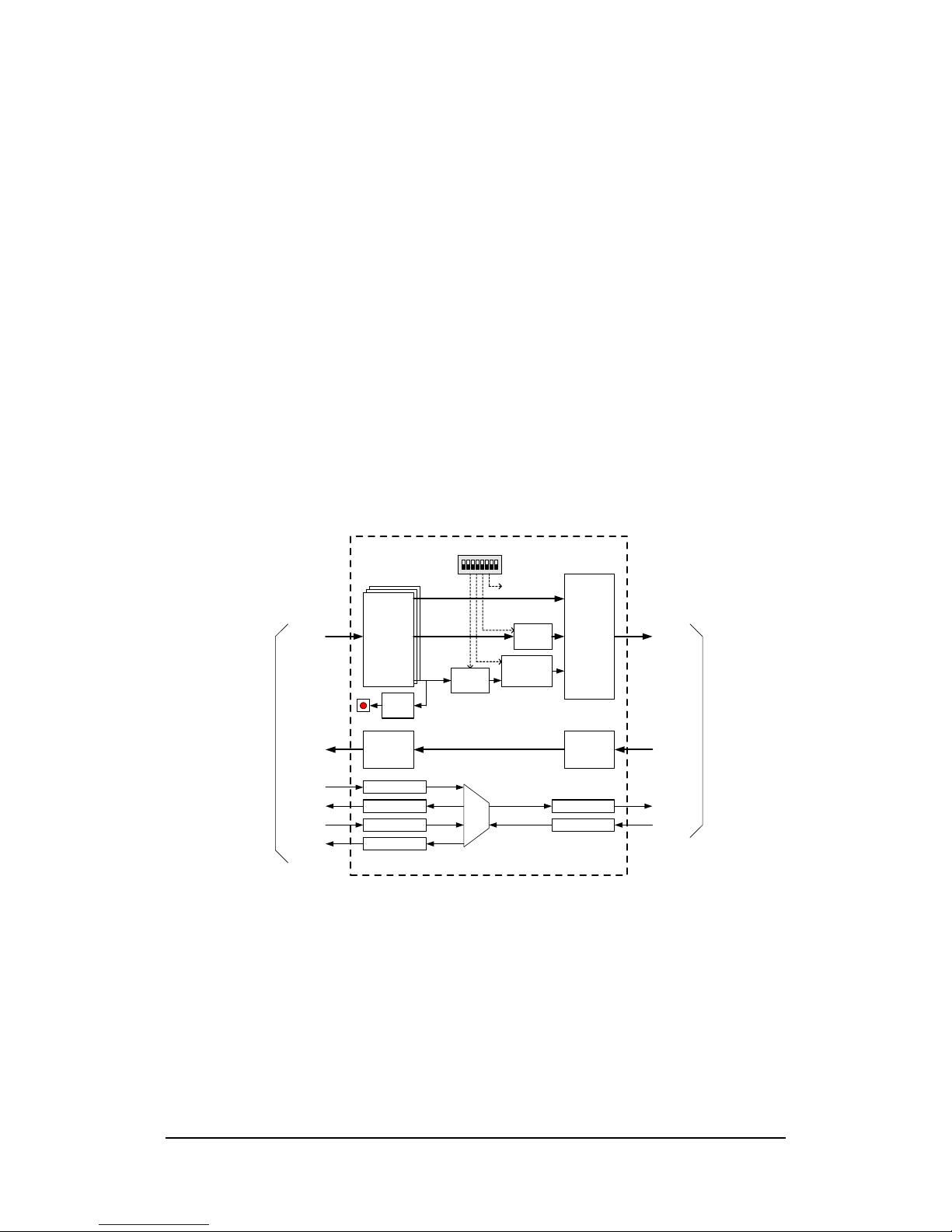
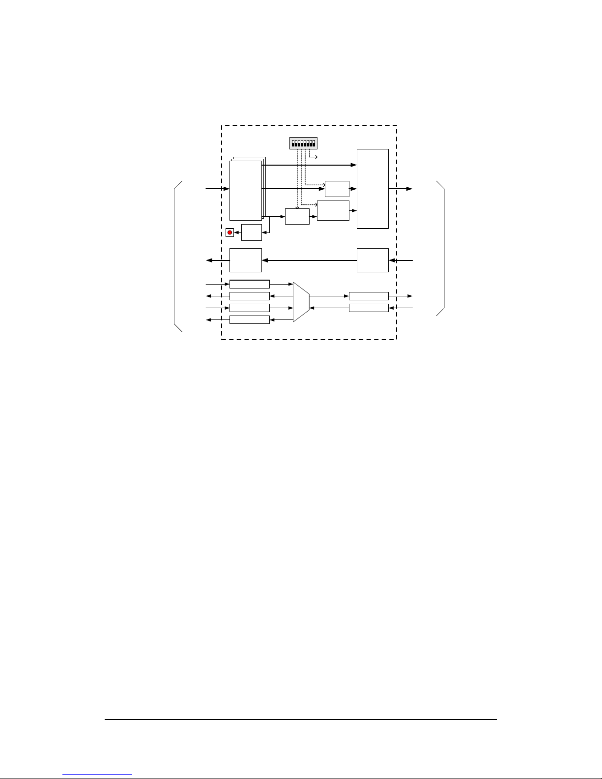
The CLT-302 receives parallel digital camera data on the 100-pin camera connector and
maps the pixel data into the corresponding Camera Link “base” configuration format. The
CLT supports single-channel (monochrome) cameras with 8/10/12/14/16-bit pixels, dual-
channel 8/10/12-bit cameras, and 8-bit color cameras.
The latency (i.e. delay) of the video, control, and communication signals passing through
the CLT-302 is minimal. This is an important criteria in some time-critical application.
The delay for the camera video through the CLT-302 is only a few pixel clock periods.
See Table 1.1 for CLT-302 latency specifications.
Camera timing signal characteristics are selected using the rear-panel mode switch. One
switch position is used to select the polarity of the line valid signal, and a second switch
position is used to select the polarity of the frame valid signal. In most cases, a “high”
state on the line enable and frame enable signals is used to envelope valid lines and
frames of video data, respectively. The settings enable the user to select either active-high
or active-low polarities for each timing signal. Note that the frame enable signal is not
used in line scan applications. Switch settings are defined in Section 1.3.1.
Camera Link incorporates a data valid signal which is used to qualify the video data. This
signal is generated by the CLT-302 and sent to the Camera Link frame grabber. Most
LVDS and RS-422 digital cameras do not incorporate a data valid type signal. The CLT-
302 incorporates a provision for the rare cases in which a data valid is provided by the
camera. When the data valid pass-through dip switch position is raised, the CLT-302
passes the data valid signal from the camera to the frame grabber. The Camera Link data
valid input is active-high, qualifying the incoming video data when the signal is high. A
second dipswitch position, data valid polarity, supports either active-high or active-low
data valid signals from the camera. When the data valid pass-through dipswitch is in the
normal (low) position, the CLT-302 maintains the data valid signal sent to the frame
grabber in the high position. The only exception is when the clock multiplier is being used
which is discussed next.
Camera pixel clock characteristics are selected using the rear-panel mode switch. One
switch position is used to select which pixel clock edge, rising or falling, is used to sample
the data and timing signals received from the camera. Two additional switch positions are
used to enable the CLT-302 clock multiplier circuit. The clock multiplier supports the use
of camera with pixel clock frequency below the Camera Link 20MHz minimum by
“multiplying” the camera clock frequency before it is sent to the Camera Link frame
grabber.. For cameras with pixel clocks in the 10-19.99 MHz range, the clock multiplier is
used to 2x (i.e. double) the clock frequency. For cameras with pixel clocks in the 5-9.99
MHz range, the clock multiplier is used to 4x (i.e. quadruple) the clock frequency. For
cameras with pixel clocks in the 2.5-4.99 MHz range, the clock multiplier is used to 8x the
clock frequency.

7
The result of using the clock multiplier is a 2x/4x/8x oversampling of camera data and
timing signals sent to the Camera Link frame grabber. When in 2x/4x/8x mode, the CLT-
302L & CLT-302R toggles the “data valid” signal defined in the Camera Link
Specification accordingly. If the frame grabber supports the data valid signal, the
oversampling affect is removed automatically. Otherwise, the oversampling is easily
removed in the frame grabber by adjusting the line timing (multiply by 2/4/8) and
decimating (divide by 2/4/8) the pixels in the “X” dimension. Two switch positions are
used to select camera clock characteristics. Switch settings are defined in Section 1.3.1.
The CLT-302 receives four LVDS camera control signals from the Camera Link frame
grabber and retransmits all four signals to the camera using LVDS or RS-422 signaling,
depending on CLT-302 version. These signals are often used to externally synchronize
the camera (i.e. EXSYNC). The camera may or may not require any or all of these
signals.
The CLT-302 routes the serial communication signals between the LVDS/RS-422 digital
camera and the Camera Link frame grabber. This supports host computer access to mode
control and status registers in the camera via the serial port included in the Camera Link
frame grabber. The camera may or may not incorporate a serial port. The CLT-302
supports differential signaling (LVDS or RS-422, depending on CLT-302 version) for the
camera serial port as well as RS-232 single-ended signaling which is used with some
LVDS/RS-422 cameras. A rear-panel dipswitch is used to select the camera serial port
signaling standard (RS-422/LVDS or RS-232). Note that the LVDS/RS-422 and RS-232
serial ports use different pins on the 100-pin camera connector. The camera cable must be
correctly wired for the desired serial port signaling standard.
The CLT-302L & CLT-302R frame grabber interface incorporates LVDS devices for the
serial communication signals (per Camera Link). The camera interface serial signals are
implemented using LVDS or RS-422 devices, depending on CLT-302 version.
The CLT-302 detects the presence of an active Camera Link camera. When an active (i.e.
powered) camera is detected, the front-panel “link” indicator illuminates. The front panel
also includes a power indicator to show that the CLT-302 is powered.

8
The CLT-302 is powered by an external wall plug-in power supply. A multi-nation power
supply is standard. Optionally, the CLT-302 is available with a locking power supply
connector. The locking power supply connector reduces the risk of accidental
disconnection. The CLT-302 is also available without any power supply for customers
who want to provide their own power source.
Note: The CLT-302 requires a steady, continuous pixel clock from the camera.

9
1.3.1. Mode Switch Settings
The CLT-302 incorporates a rear-panel mode select switch. The switch allows the
user to identify camera timing signal, serial communication, and clock characteristics.
The mode switch has eight positions. The functional assignments are defined in
Figure 1-3.
Frame Valid Polarity
1 - active-low
0 - active-high (most common)
1 2 3 4 5 6 7 8
1 = "up" switch position
0 = "down" switch position
Line Valid Polarity
1 - active-low
0 - active-high (most common)
Data Valid Polarity
1 - active-low
0 - active-high (most common)
Clock Edge
1 - falling edge
0 - rising edge (most common)
Data Valid Pass-Through
1 - enabled
0 - disabled (most common)
Serial Comm Select
1 - RS-232
0 - LVDS (CLT-302L) or RS-422 (CLT-302R)
Clock Multiplier
1 1 - 8x
0 1 - 4x
1 0 - 2x
0 0 - Disabled (most common)
Figure 1-3: CLT-302 Mode Switch Definition
Note: Normal (default) dipswitch settings are “all-low” as shown above

10
1.4. Typical Application
A typical CLT-302 application is shown in Figure 1-4. An LVDS camera is connected to
the CLT-302L using a camera cable that incorporates a 100-pin connector and pin
assignments for use with the CLT-302L and RS-232 camera communication . The CLT-
302L is connected to the frame grabber using a standard Camera Link cable.
The camera in this example is 8-bit, dual-channel, area-scan with a 20MHz pixel clock
and LVDS signaling. The frame enable and line enable timing signals are conventional
active-high. The camera does not generate a data valid signal. Data sampling was found
to be best performed using the falling edge of the camera pixel clock, which is sometimes
the case. In addition, the serial control port on the camera is RS-232. The corresponding
mode switch settings are shown in Figure 1-5. Note that the clock multiplier feature is not
required in this example since the pixel clock is within the 20-85 MHz range required by
Camera Link.
The Camera Link frame grabber is programmed for area-scan, base-configuration, dual-
channel, 8-bit mode. The pixel clock rate is set at 20MHz and video timing is set to match
camera characteristics.
Camera control signal CC1 is routed from the frame grabber, through the CLT-302L, to
the camera for use as an EXSYNC pulse, exposure control, etc.
The serial port in the Camera Link frame grabber is used to control and monitor camera
functions.
LVDS
Camera
Camera Link
Frame Grabber
CLT-302L
Camera Link Translator
Camera Cable
Camera Link Cable
V
ivid
E
ngineering
Camera Link Translator CLT-302L
LVDS CAMERAPOWER LINK
Figure 1-4: CLT-302 Typical Application

11
Frame Valid Polarity
0 - active-high (most common)
1 2 3 4 5 6 7 8
1 = "up" switch position
0 = "down" switch position
Line Valid Polarity
0 - active-high (most common)
Data Valid Polarity
0 - active-high (most common)
Clock Edge
1 - falling edge
Data Valid Pass-Through
0 - disabled (most common)
Serial Comm Select
1 - RS-232
Clock Multiplier
0 0 - Disabled (most common)
Figure 1-5: Example Mode Settings

12
1.5. Specifications
Table 1-1: CLT-302L & CLT-302R Specifications
Feature
Specification
Camera Interface - “R” version = Parallel RS-422
- “L” version = Parallel LVDS (EIA-644)
Camera Connector 100-pin SCSI-style
Frame Grabber Interface Camera Link “base” configuration
Frame Grabber Connector 26-pin MDR type
Camera Frequency - “R” version: 2.5 - 32 MHz
- “L” version: 2.5 - 85 MHz
Mode Selection Rear-panel 8-position DIP switch
Latency Video path: 3 camera pixel clock cycles
Control signals: 20 ns max
Power Supply Universal wall style w/ outlet plug set
Power Jack 2.1 x 5.5 mm, center-positive. Locking style optional
Power Requirements 4.5 – 6.0 VDC, internally isolated
- 300 mA @ 5 VDC (typical)
Cabinet Dimensions 5.28” (L) x 1.12” (H) x 6.13” (D)
Weight 13 oz
Operating Temperature Range 0 to 50° C
Storage Temperature Range -25 to 75° C
Relative Humidity 0 to 90%, non-condensing
Compliance FCC Class A, ROHS, CE EN55024 pending

13
2. Interface
2.1. Front Panel Connections
A CLT-302L & CLT-302R Camera Link Translator front panel is shown in Figure 2-1
(CLT-302L shown). The front panel contains a 100-pin video connector for connecting to
the camera , an LED power indicator, and an LED link indicator. The camera connector is
a 100-pin SCSI-style, TE Connectivity p/n 5787170-9. Included are two jackscrew
sockets (TE Connectivity p/n 749087-2) that mate with camera cable 2-56 thread
jackscrews. Figure 2-2 identifies the pin positions.
V
ivid
E
ngineering
Camera Link Translator CLT-302L
LVDS CAMERAPOWER LINK
Figure 2-1: CLT-302L Front Panel
pin 1
pin 50
pin 51
pin 100
Figure 2-2: 100-pin Camera Connector Pin Positions

14
2.1.1. Camera Connector Signals
Tables 2-1 through 2-5 identify the 100-pin camera connector signal assignments for
single-channel pixel data modes (1x8, 1x10, 1x12, 1x14, and 1x16). Tables 2-6
through 2-8 identify the signal assignment for dual-channel modes (2x8, 2x10, 2x12),
and Table 2-9 identifies the signal assignment for color mode (3x8). The
appropriate table must be used when making a camera cable for use with the
CLT-302.
2.1.2. Camera Cable Shielding and Grounding
At a minimum, one digital ground pin at the camera connector must be connected to
one of the digital ground pins on the CLT-302 connector in order to maintaining
signal reference levels between camera and CLT-302. Camera cable “inner” shields
(if present) should connect to CLT-302 digital ground pins.
Camera cable “outer” shields should attach to the metallic connector shell, which
contacts the CLT-302 aluminum enclosure. CLT-302 enclosure body and endplate
contacting surfaces are unpainted, providing a Faraday cage to shield the internal
circuitry. The enclosure is isolated from the CLT-302 circuitry, avoiding possible
safety concerns.
2.1.3. Camera Cable Recommended Connectors
The camera connector used in the CLT-302 is made by TE Connectivity
(www.te.com, formerly Tyco and originally Amp). The connector part number is
identified in Section 2.1. The following is a list of recommended mating connectors
and hardware for use in camera cables:
Plug, TE Connectivity p/n 1-5750913-9
Plug, TE Connectivity p/n 5749111-8
Plug, TE Connectivity p/n 5749621-9
Backshell, TE Connectivity p/n 5749854-1
Backshell, TE Connectivity p/n 5749081-1

15
Table 2-1: Camera Connector, 8-bit Single-Channel Mode
Camera Interface
Signal Name
Camera Interface
Connector Pin Signal Direction Notes
A0 + 1 CAM →CLT-302
A0 - 2 CAM →CLT-302
A1 + 3 CAM →CLT-302
A1 - 4 CAM →CLT-302
A2 + 5 CAM →CLT-302
A2 - 6 CAM →CLT-302
A3 + 7 CAM →CLT-302
A3 - 8 CAM →CLT-302
A4 + 9 CAM →CLT-302
A4 - 10 CAM →CLT-302
A5 + 11 CAM →CLT-302
A5 - 12 CAM →CLT-302
A6 + 13 CAM →CLT-302
A6 - 14 CAM →CLT-302
A7 +115 CAM →CLT-302
A7 -116 CAM →CLT-302
Unused Input 17 CAM →CLT-302
Unused Input 18 CAM →CLT-302
Unused Input 19 CAM →CLT-302
Unused Input 20 CAM →CLT-302
Unused Input 21 CAM →CLT-302
Unused Input 22 CAM →CLT-302
Unused Input 23 CAM →CLT-302
Unused Input 24 CAM →CLT-302
Unused Input 25 CAM →CLT-302
Unused Input 26 CAM →CLT-302
Unused Input 27 CAM →CLT-302
Unused Input 28 CAM →CLT-302
Unused Input 29 CAM →CLT-302
Unused Input 30 CAM →CLT-302

16
Unused Input 31 CAM →CLT-302
Unused Input 32 CAM →CLT-302
Mode Control 0 + 33 CLT-302 →CAM CC1 from FG
Mode Control 0 - 34 CLT-302 →CAM ”
Mode Control 1 + 35 CLT-302 →CAM CC2 from FG
Mode Control 1 - 36 CLT-302 →CAM ”
Mode Control 2 + 37 CLT-302 →CAM CC3 from FG
Mode Control 2 - 38 CLT-302 →CAM ”
Mode Control 3 + 39 CLT-302 →CAM CC4 from FG
Mode Control 3 - 40 CLT-302 →CAM ”
Frame Enable + 41 CAM →CLT-302 “frame valid”
Frame Enable - 42 CAM →CLT-302 “
Line Enable + 43 CAM →CLT-302 “line valid”
Line Enable - 44 CAM →CLT-302 “
Data Valid + 45 CAM →CLT-302 “data valid”
Data Valid - 46 CAM →CLT-302 “
Ground 47 N/A
tied to digital ground
Ground 48 N/A
tied to digital ground
Pixel Strobe + 49 CAM →CLT-302 “pixel clock”
Pixel Strobe - 50 CAM →CLT-302 “
Unused Input 51 CAM →CLT-302
Unused Input 52 CAM →CLT-302
Unused Input 53 CAM →CLT-302
Unused Input 54 CAM →CLT-302
Unused Input 55 CAM →CLT-302
Unused Input 56 CAM →CLT-302
Unused Input 57 CAM →CLT-302
Unused Input 58 CAM →CLT-302
Unused Input 59 CAM →CLT-302
Unused Input 60 CAM →CLT-302
Unused Input 61 CAM →CLT-302
Unused Input 62 CAM →CLT-302
Unused Input 63 CAM →CLT-302
Unused Input 64 CAM →CLT-302
Unused Input 65 CAM →CLT-302
Unused Input 66 CAM →CLT-302

17
Not Used 67 N/A
Not Used 68 N/A
Not Used 69 N/A
Not Used 70 N/A
Not Used 71 N/A
Not Used 72 N/A
Not Used 73 N/A
Not Used 74 N/A
Not Used 75 N/A
Not Used 76 N/A
Not Used 77 N/A
Not Used 78 N/A
Not Used 79 N/A
Not Used 80 N/A
Not Used 81 N/A
Not Used 82 N/A
Not Used 83 N/A
Not Used 84 N/A
Not Used 85 N/A
Not Used 86 N/A
Not Used 87 N/A
Not Used 88 N/A
Serial Control Out + 89 CLT-302 →CAM serial comm, FG to cam
Serial Control Out - 90 CLT-302 →CAM “
Serial Control In + 91 CAM →CLT-302 serial comm, cam to FG
Serial Control In - 92 CAM →CLT-302 “
RS-232 Comm Out 93 CLT-302 →CAM RS-232 comm, FG to cam
This manual suits for next models
1
Table of contents
Other Vivid Camera Accessories manuals