Vivid CLB-501B User manual

CLB-501B CAMERA LINK BREAKOUT BOX
User’s Manual
Document # 201107, Rev 0.2, 3/23/2012 preliminary
Vivid Engineering
159 Memorial Drive, Suite F • Shrewsbury, MA 01545
Phone 508.842.0165 • Fax 508.842.8930
www.vividengineering.com • info@vividengineering.com

Table of Contents
1. Introduction 1
1.1. Overview 1
1.2. Features 2
1.3. Functional Description 3
1.3.1. Breakout Header Pixel Assignments 5
1.4. Typical Application 11
1.5. Specifications 12
2. Interface 13
2.1. Front Panel 13
2.1.1. Video Connectors 14
2.1.2. Cable Shield Grounding 14
2.2. Rear Panel 15
2.2.1. Breakout Header Signals 16
2.2.2. Auxiliary Header Signals 17
3. Mechanical 18
3.1. Dimensions 18
3.2. External Power Supply 19
4. Revision History 20

1
1. Introduction
1.1. Overview
The CLB-501B Camera Link1Breakout Box provides convenient access to the data
transferred between camera and frame grabber over a Camera Link connection. All video,
control, and communication data can be monitored and/or sourced via a standard header
connector located on the rear panel.
CLB-501B incorporates high-speed 85MHz interfaces and is compatible with all Camera
Link “base” configuration cameras. “Medium” configuration applications are supported
using two CLB-501B’s. Features include a camera signal detect indicator and isolated DC
power input
The CLB-501B Camera Link Breakout Box is housed in sturdy, compact aluminum
enclosures. A locking-plug power supply is optional.
V
ivid
E
ngineering
Camera Link Breakout Box CLB-501B
CAMERA FRAME GRABBER
PWR
LINK
1The Camera Link interface standard enables the interoperability of cameras and frame grabbers,
regardless of vendor. The Automated Imaging Association (AIA) sponsors the Camera Link
program including the oversight Camera Link Committee, the self-certification program, and the
product registry. The Camera Link specification may be downloaded from the AIA website, found
at www.machinevisiononline.org
Camera Link is a trademark of the Automated Imaging Association

2
1.2. Features
•Provides access to all data (video, camera control, serial comm.)
•Standard 0.1” pitch dual-row header-style breakout connector
•Removable header jumpers (shunts) enable external data sourcing
•Standard LVTTL signal levels
•Power, ground, and buffered clock pins aide interfacing
•Uses standard Camera Link cables (not included)
•Supports Camera Link “base” configuration
•High-speed 85 MHz interface chipset, works with any base camera
•“Medium” configuration support using two CLB-501Bs
•Also acts as a repeater, doubling max distance between camera and frame grabber
•Link indicator
•Isolated DC power input
•Minimal data pass-through latency
•Sturdy, compact aluminum enclosure w/ mounting flange
•Multi-nation power supply included, locking-plug power supply optional
•3-year warrantee
3
1.3. Functional Description
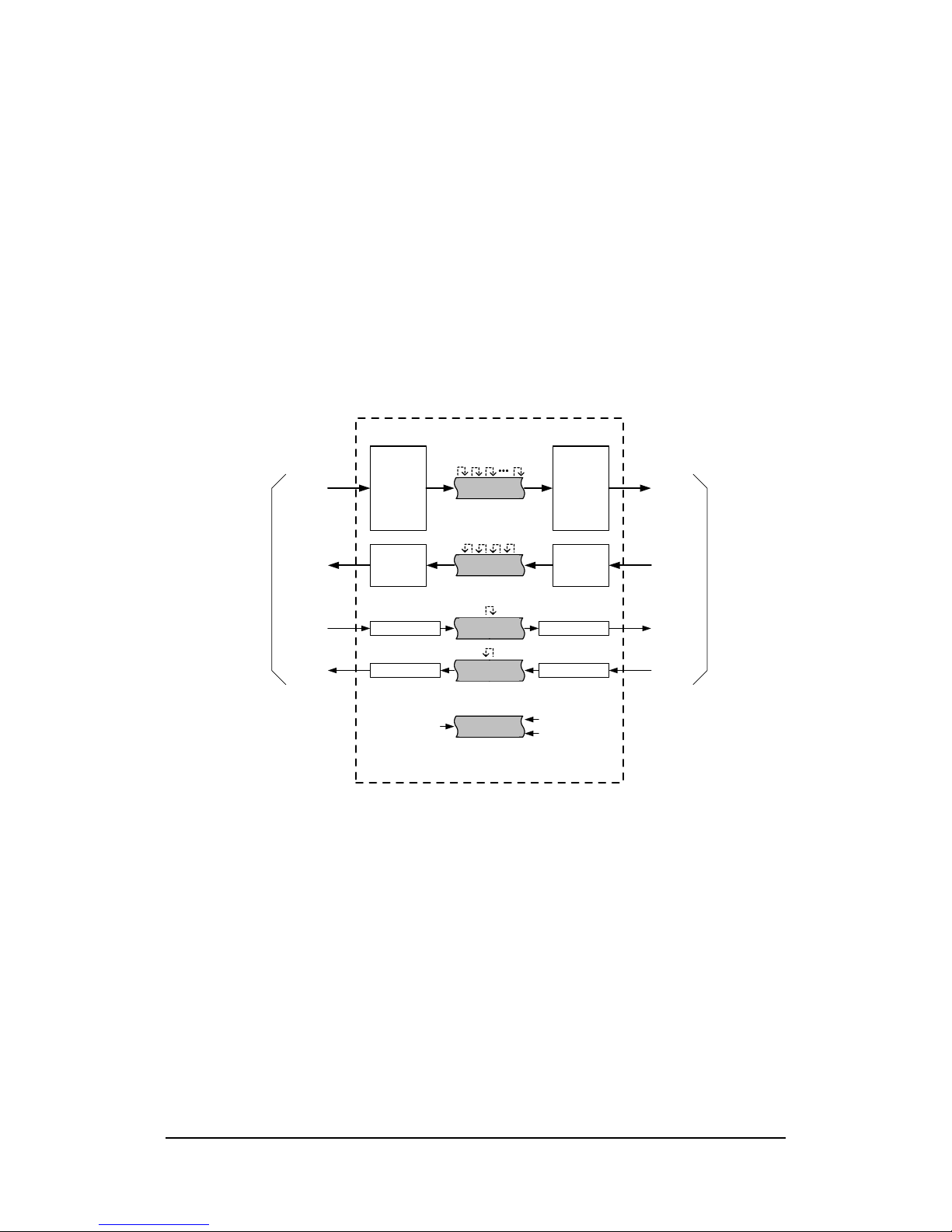
A block diagram of the CLB-501B is provided in Figure 1-1. The CLB-501B provides
access to the data transferred between camera and frame grabber over a Camera Link
connection. All video, control, and communication data can be monitored and/or sourced
via a header-style breakout connector located on the rear panel.
The CLB-501B incorporates the connectors, signals, pinouts, and chipset in compliance
with the Camera Link specification for the “base” configuration.
Channel
Link
Receiver
Channel
Link
Transmitter
LVDS
Receiver
LVDS
Transmitter
LVDS Rcvr
To Camera Link Camera
Video
Data
Camera
Control
Serial
Comm
Link
LVDS Xmtr
LVDS Xmtr
LVDS Rcvr
Video
Data
Camera
Control
Serial
Comm
Link
To Camera Link Frame Grabber
CLB-501B Camera Link Breakout Box
Rear-Panel
Header
Rear-Panel
Header
Rear-Panel
Header
Rear-Panel
Header
Rear-Panel
Header
buffered
pixel clock
+3.3 vdc
ground
Figure 1-1: CLB-501B Block Diagram
The CLB-501B breakout connector is a standard dual-row header for easy connection to
external test equipment and is located on the rear panel. The unit comes with a complete
set of shorting blocks (shunts) installed on the header. The shunts may be removed to
break the connection between camera and frame grabber in order to insert an external data
source (i.e. for camera control, serial comm., etc.). Since all video data is available at the
header, the CLB-501B may also be used to remap/realign video and control information
between camera and frame grabber.

4
To aide in interfacing to external equipment, the CLB-501B incorporates and auxiliary
header that provides 3.3VDC power, ground, and a buffered version of the pixel clock.
The buffered clock enables access to the reference clock without the risk of degradation of
the raw clock signal which could cause a malfunction. The raw (unbuffered) pixel clock is
also available on the header, but care should be taken in its use. The buffered clock is
sourced from the output (frame grabber) side of the breakout header.
All signals on the header utilize standard LVTTL levels. Care must be taken when
interfacing to the header to avoid damage to the internal components.
The CLB-501B incorporates high-speed (85MHz) interfaces and is compatible with any
“base” configuration camera. “Medium” configuration applications are supported using
two CLB-501B’s in parallel. The CLB-501B does not support the Camera Link “full”
configuration.
The latency (i.e. delay) of the video, control, and communication signals passing through
the CLB-501B is minimal. This is an important criteria in time-critical applications. See
Table 1.1 for the latency specifications.
CLB-501B also acts as a repeater and doubles the maximum separation between the
camera and the frame grabbers.
A front-panel link status indicator illuminates when the camera video signal is detected.
The front panel also includes a power indicator.
The CLB-501B is powered by an external wall plug-in power supply. A multi-nation
power supply is standard. Optionally, the CLB-501B is available with a locking-plug
power supply. The locking plug reduces the risk of accidental disconnection from the
rear-panel power jack. The CLB-501B is also available without power supply.
The CLB-501B DC power input is electrically isolated from the internal circuitry. This
feature ensures compatibility with user power systems.
5
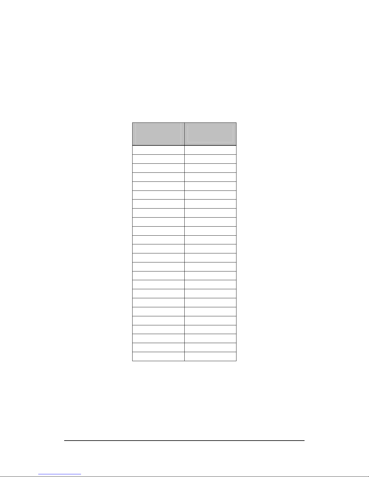
1.3.1. Breakout Header Pixel Assignments
Tables 1-1 through 1-6 identify the assignment of camera pixel data to the breakout
header pins for the Camera Link “base” configuration modes.
Table 1-1: Pixel Assignment, 8-bit x 1~3 Modes
Camera Link
Pixel Assignment
CLB-501B
Breakout
Pin
A0 D0
A1 D1
A2 D2
A3 D3
A4 D4
A5 D6
A6 D27
A7 D5
B0 D7
B1 D8
B2 D9
B3 D12
B4 D13
B5 D14
B6 D10
B7 D11
C0 D15
C1 D18
C2 D19
C3 D20
C4 D21
C5 D22
C6 D16
C7 D17
6
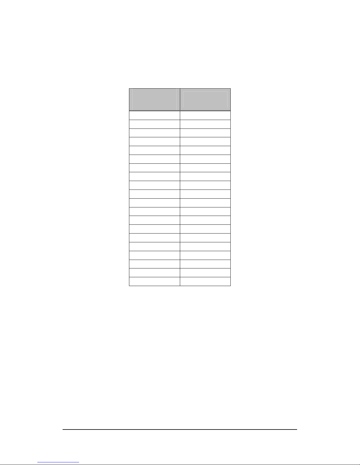
Table 1-2: Pixel Assignment, 10-bit x 1~2 Modes
Camera Link
Pixel Assignment
CLB-501B
Breakout
Pin
A0 D0
A1 D1
A2 D2
A3 D3
A4 D4
A5 D6
A6 D27
A7 D5
A8 D7
A9 D8
B0 D15
B1 D18
B2 D19
B3 D20
B4 D21
B5 D22
B6 D16
B7 D17
B8 D13
B9 D14
7
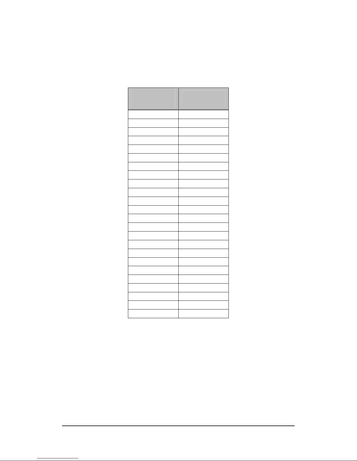
Table 1-3: Pixel Assignment, 12-bit x 1~2 Modes
Camera Link
Pixel Assignment
CLB-501B
Breakout
Pin
A0 D0
A1 D1
A2 D2
A3 D3
A4 D4
A5 D6
A6 D27
A7 D5
A8 D7
A9 D8
A10 D9
A11 D12
B0 D15
B1 D18
B2 D19
B3 D20
B4 D21
B5 D22
B6 D16
B7 D17
B8 D13
B9 D14
B10 D10
B11 D11
8
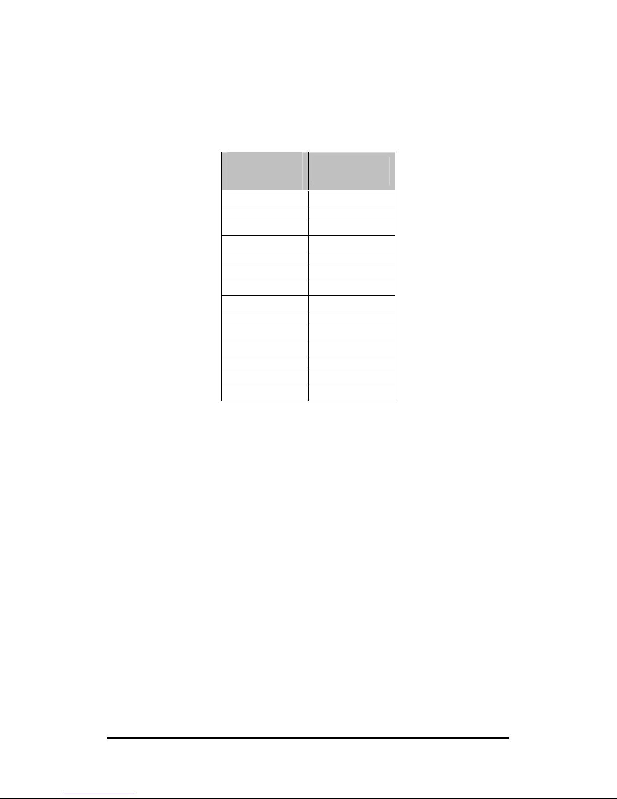
Table 1-4: Pixel Assignment, 14-bit x 1 Mode
Camera Link
Pixel Assignment
CLB-501B
Breakout
Pin
A0 D0
A1 D1
A2 D2
A3 D3
A4 D4
A5 D6
A6 D27
A7 D5
A8 D7
A9 D8
A10 D9
A11 D12
A12 D13
A13 D14
Table of contents
Other Vivid Camera Accessories manuals


Popular Camera Accessories manuals by other brands

Viltrox
Viltrox EF-NEX Mount instructions

Calumet
Calumet 7100 Series CK7114 operating instructions

Ropox
Ropox 4Single Series User manual and installation instructions

Cambo
Cambo Wide DS Digital Series Main operating instructions

Samsung
Samsung SHG-120 Specification sheet

Ryobi
Ryobi BPL-1820 Owner's operating manual


