Vivint Pandora360 User manual

Page 1 of 15
Vivint Pandora360
Operating Instructions
Title
Pandora360 Operatin
g
Instructions
Id
805-SXC0002-001
Type
Customer Operation Instruction
Prepared
P. Estelius
Date
2018-09-22
Security
Internal
Revision
A
1.
1. Introduction
2. Radio Frequency Exposure
3. Directions for Use
o 3.1. Preconditions
o 3.2. Intended Use
4. Installation Procedure
o 4.1. Tools for Installation
o 4.2. Unpacking
o 4.3. Installing
4.3.1. Pole Installation
4.3.2. Cable Installation
4.3.3. Pandora360 Installation
4.3.4. Testing the Installation
4.3.5. Software Installation
5. Technical Specification
6. Fault, Possible Causes, and Remedies
7. Standards
8. Glossary
Page 2 of 15
1. Introduction
Vivint Pandora360 is an outdoor (Multi)Point-to-Multipoint TDD radio in the unlicensed V-band
(57-64 GHz) based on WiGig technology, IEEE 802.11ad. It can provide 2 Gbps user traffic in
each direction (four directions giving 8 Gbps in total). Pandora360 comes in two versions, either
with an additional LAN port, or with an SFP+ (10Gbps) port. It is powered by proprietary Power
over Ethernet (PoE) or 48 VDC. When using 48 VDC power, alarm signals are also available
from the UPS in the same cable as the DC cable. Operations and Maintenance is done via the
LAN port or the or SFP+ port. (802.11b/g/n) is used for maintenance operations when a field
technician is within close proximity to the equipment.
Pandora360 is used for broadband coverage, primarily for households.
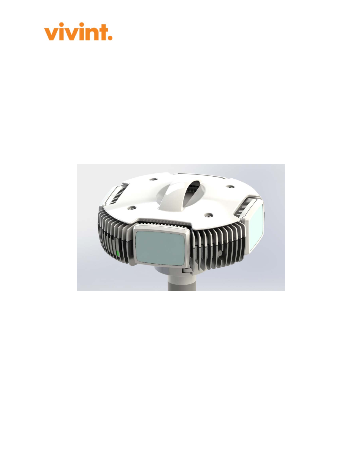
Figure 1: A Pandora360 Node
The Pandora360 consist of four microwave radio nodes in one box. The internal "nodes" are
physically placed 90 degrees apart and each lobe can be horizontally adjusted +/-40 degrees so
that the sectors together covers 360 degrees. This provides four branches per node to connect
with other Pandora360 nodes as required.

Page 3 of 15
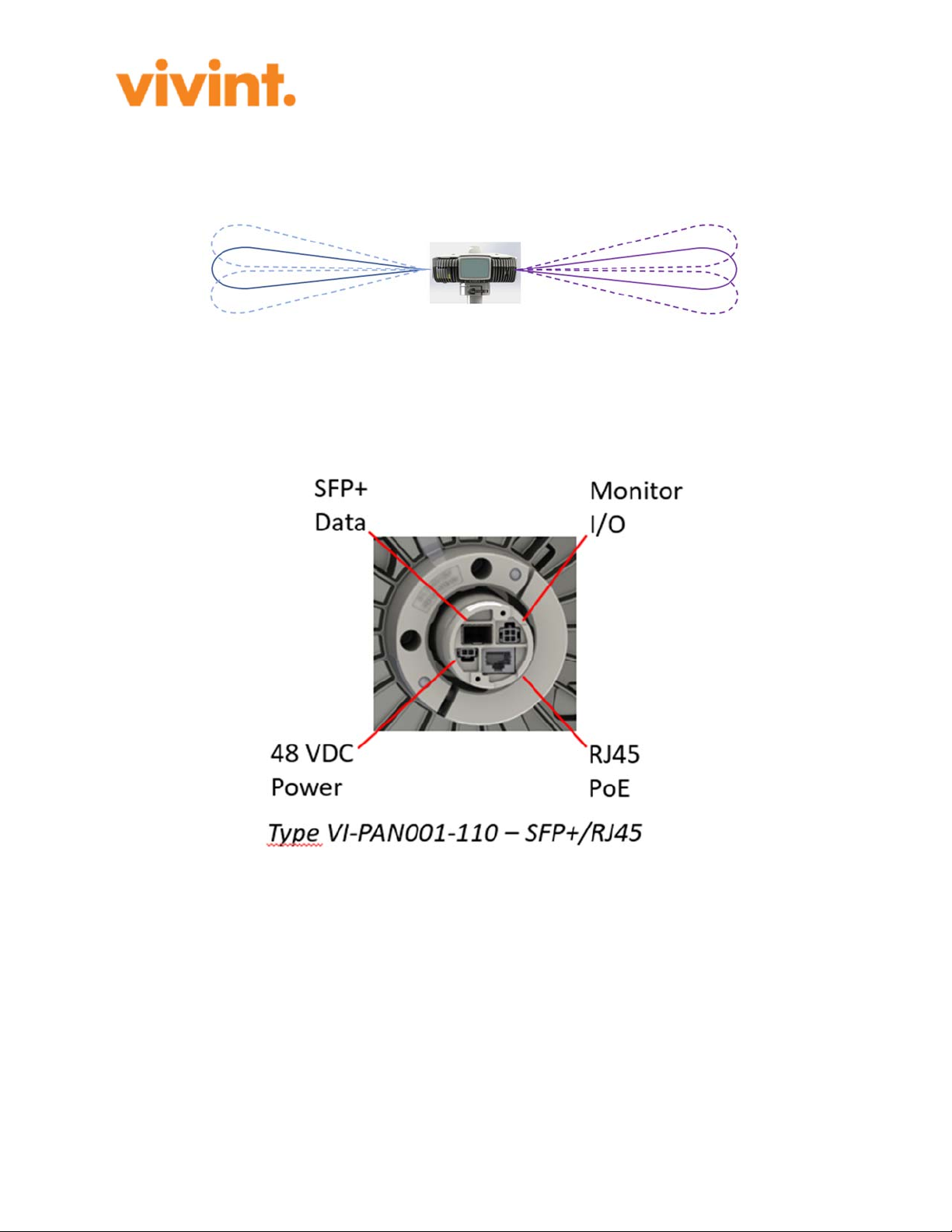
Figure 2: Horizontal Radio Sectors on the Pandora360 Node,
Page 4 of 15
The radio lobes can be vertically adjusted +/-15 degrees to cover uneven ground and different
roof heights. All adjustments, both horizontally and vertically, are done electronically via
software running on the Qualcomm baseband and RF chipset.
Figure 3: Vertical adjustment of the Pandora360 Radio Lobe.
The Pandora360 comes in two variants, one with two RJ45 Ethernet connections, and one for
one RJ45 and one SFP+ Ethernet connection. Both variants deliver Gigabit connections on both
inputs.

Page 5 of 15
Figure 4: SFP+/RJ45 Connection Figure 5: RJ45/RJ45 Connections
2. Radio Frequency Exposure
This product complies with FCC radiation exposure limits for an uncontrolled environment.
Avoid operating this product at a distance less than 11 in (28 cm) from the user.
3. Directions for Use
The Pandora360 is designed for outdoor use in broadband radio mesh setups. This means for
example University campuses, local housing areas, etc. The small size makes it less obvious in
the environment, and its WiFi management connection makes local management and
maintenance from ground safe and easy for the maintenance personnel. The device can be
installed in meshes with at least 200 nodes, all managed via a common network management
system.
The Pandora360 node enables fast deployment of wireless broadband provisioning to end
customers in smaller areas like smaller communities or housing areas. It comes with broadband
internet through a so called Seed Node where the network first is connected, and then the
broadband internet is delivered to the rest of the nodes in the network through short range
wireless broadband microwave radios.

Page 6 of 15
This kind of remote managed network provides the means for building the network at a pace
fitting the area and must not be fully deployed before taken into use.
Hands on work on the equipment is only required at installation, or if service is required.
3.1. Preconditions
The preconditions for using a Pandora360 is that the installation and use in all parts follow what
has been stated by the supplier and manufacturer.
All other uses must be clarified and approved by the supplier/manufacturer! If not it is regarded
as a non-approved installation which will become the sole responsibility of the installer.
3.2. Intended Use
The Pandora360 is intended for outdoor use in broadband mesh configurations. It is managed
and maintained remotely using the Node Management System software on a local PC through
the network using the ACS and SNMP servers.
4. Installation Procedure
This section covers how to install a Pandora360 and make initial installation test before taking
the node into operation.
NOTE: All cables used should be shielded.
4.1. Tools for Installation
The following tools are required to safely and correctly install a Pandora360 node.
Required:
Power Tool with 10 mm socket (capable of a defined torque)
Screwdriver (Philips Ph2)
In case of installation with -48V
Cutting Plier
Crimping Plier
Knife
4.2. Unpacking

Page 7 of 15
The Pandora360 comes in a wellboard box lined with specially cast plastic foam lining.
Start by cutting the box sealing tape and take out the parts. Each box includes the following
parts:
One Pandora360 Node.
One bag with Strain Relief parts,
One bag with Gasket and plugs for complete weather proofing of the different cable
connections.
4.3. Installing
The Pandora360 node is installed as follows:
4.3.1. Pole Installation
Pandora360 installer's Tools will direct the installer where the unit can be located on the roof
(typically a polygon is defined). The unit will need to report it's correct GPS position back to the
IT systems to verify the node is installed at the correct site. (If this is not verified the installer
will not be able to complete the installation process.) This roof-top location should be a place
close to the top of the roof that allows for line-of-sight to neighboring nodes as provided by the
planning data.
On the roof:
1. Mark the proper location for the pole as indicated by the Installer's Tool.
2. Check that line-of-site to adjacent Pandora360s are free.
3. Mount the foot and the pole on the roof so that the pole is truly vertical. (Make sure that
the installation is done according to local regulations to prevent leaks etc.)
4. Mount the support struts for the pole.
4.3.2. Cable Installation
Use the following cable types for the installation:
Connection Cable type/Part
Number Name
PoE & LAN ECB0012/xxx 24 AWG CAT5e outdoor SFTP (Shielded Foiled
Twisted Pair) cable, blac
k
Optical Fibre
Cable ACC0004/xxx LC-LC Single mode 1310 nm with short fanout
b
ecause of strain relief for outdoor use
DC & I/O ECB0014/xxx (6x) 20 AWG shielded (foil and braid)

Page 8 of 15
Groundin
g
ECB0013/xxx Groundin
g
cable colors to be used, 10 AWG (6 mm2)
SFP+ EGE0015/xxxx Finisa
r
10GBASE-LR,1310 nm, 1.4 km, SM, LC
After collecting the applicable cables, do the following:
1. Pull the cables to be connected to the pole on roof top.
2. Pull the cables through the pole (from bottom to top).
3. The cables are either already terminated with appropriate connectors or can be terminated
and crimped on the roof.
4. In case of field termination, crimp the connectors to the cables
4.3.3. Pandora360 Installation
Install the Strain Relief with the two MRT M3x8 screws to the bottom side of Pandora360 in
preparation for cable connection.
Take the Pandora360 node together with sleeve gasket and sleeve gasket plug up on the roof to
the point of installation.
1. Fit the Strain Relief Gasket and pull cable through.
2. Connect cables in the following order:
1. Start with the grounding (GND) cables, make sure the grounding cable is properly
terminated (Fork lug for 4mm screw) and well secured to the Earthing screw on
the Strain Relief.
2. Fit the Data cables (RJ45 or SFP respectively)
3. Connect power cables
1. If PoE is used to supply the Pandora360 with Power, make sure that the
data connector is connected in the black RJ45 connector
2. if DC feed is used, make sure also to connect the I/O cable
3. Secure the connected cables with the wing screw to the strain relief
4. Securing cables to be weatherproof
1. Put the cables in sleeve gasket plug
2. Make sure that unused slots have the correct dummy plugs inserted
3. Put the plug in the sleeve gasket
4. Slide the sleeve gasket in place and make sure that the itsit fits in to the grove on
Pandora360 node
5. Fit node end into pole while gently pulling the cables out at the foot of the pole
6. Rotate to desired orientation.
7. Tighten the C-clamp screw according to torque requirements.
8. Make a service loop of the cable at bottom of pole
4.3.4. Testing the Installation

Page 9 of 15
As soon as the Pandora360 node is connected to the network, it automatically registers itself
towards the Vivint System which sends the appropriate configuration to the node, The node then
automatically applies the new configuration and is from then on an active part in the network.
While the node restarts with the new configuration, the network management personnel monitors
the activities via the Network management System and waits for OK on:
Connected to another mesh node.
Connected to the ACS.
Configuration update complete.
GPS locked.
Customer port online and connected.
The webGUI illustrates the status off these different steps. The installer will get an OK once the
new configuration is running.
This completes the physical installation.
4.3.5. Software Installation
Before a node can be put into operation at a customer site, a customer record must be created in
Vivint's IT system. The installation process assumes that a customer record and an equipment
record exists in Vivint's IT systems. On site an installer will scan the node (label on the
Pandora360 node) in order to register the node and connect it with the customer site. At the point
of scan, the customer record and the equipment are linked to each other. This is a critical point at
which the configuration for the unit is available through the ACS. Without the scan the
equipment will not be registered with a customer and hence it will not be able to pull a valid
configuration from ACS and would not be able to authenticate through 802.1X.
The feedback the installer needs from the scanning is:
Is the node of correct type?
Is the site an LTE site and if this is the case, which IPv6 needs to be configured on the
LTE eNB?
Feedback of what type of electrical installation is needed:
o Battery backup (48V DC)
o No battery backup (PoE+)
In case a node is already registered with a site and needs to be replaced, the old equipment is
disassociated with the user account (equipment is removed from ACS but site config
maintained). When the replacement unit is scanned the customer record will be updated through
the ACS and the new node will be configured in the same way as the old unit.
With that the installation is fully tested and in operation.

Page 10 of 15
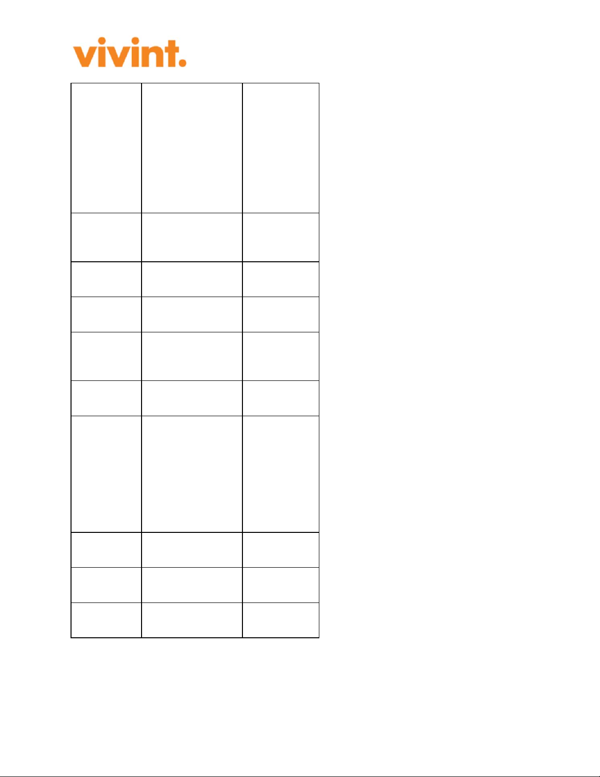
5. Technical Specification
The technical Specifications of the Pandora360 node are as follows:
Comment
Type(s) VI-PAN001-110
VI-PAN002-110
SFP+/RJ45
Unit
RJ45/RJ45
Unit
Model CE04
Radio Type (Multi)Point-to-
Multi-Point Radio
Occupied
Bandwidth:
1760 MHz
with 2160
MHz as
channel
separation
according to
IEEE
802.11a
d
Size 240x240x300 mm
Wei
g
ht 4,5k
g
Pole Size 50 mm (2")
NOTE: The
pole shall be
made of
corrosion
resistant
material and
have a
protective
coating to at
least fulfill the
Outdoor
Corrosion
Requirements
for TYPE 3S
ENCLSOURE
in UL 50E.
Page 11 of 15
Power
Supply
48 VDC, or
Proprietary PoE
Nominal
53VDC (42.5-
57VDC), 1A
max.
Input: 53VDC
(42.5-
57VDC), 1A
max
No of Radios 4
Placed 90
degerees
apart.
Radio Lobe
Width (De
g
) Approx. 5 degrees
Antenna
Gain 23 dBi Effective
Output
Power
(EIRP)
40 dBm average,
41 dBm peak
Max values
measured at
3 meters
Power
Consumption 40 W max
Operating
Frequency 58.32-62.64 GHz
TDD/TDMA.
Channel 1:
58.32 GHz
Channel 2:
60.48 GHz
Channel 3:
62.64 GHz
Traffic
connections
2xRJ45, or
1xSFP+ & 1xRJ45
Capacity
RJ45
10/100/1000BASE-
T
Capacity
SFP+ 10GBASE-LR
Page 12 of 15
WiFi
Connection IEEE 802.11b/g/n
For remote
node
management.
(2.4 GHz only
with Channels
1 to 11) with
FCC & IC ID
GPS Yes
Distance
Between
Nodes
Max: 300 m
Usa
g
e Outdoo
r
Operating
Temperature
-40°C to +55°C (-
40°F to +131°F),
Relative
Humidity
Ran
g
e
4-100%
Environment
TYPE 3S
ENCLOSURE,
IP65
When
properly
installed
(inserted and
secured) on
the pole. The
pole is part of
the TYPE 3S
ENCLOSURE
& IP65 setup.
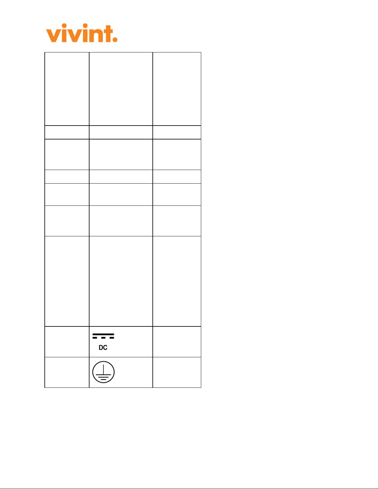
Voltage
Marking
Used for both
48 VDC and
PoE.
Protective
earth
Used as
functional
earth.
6. Fault, Possible Causes, and Remedies

Page 13 of 15
This secction covers a number of faults, their possible causes, and what can be done to remedy
the fault.
Fault Poss.
Cause Remedy Comment
Loss of
signal
No
Power
Make sure that power is ON.
Make sure that power supply fuses
are good.
Make sure the line-of-sight for the
radio is un-obstructed.
Powered by PoE, check that the
Modem/Router has power.
Powered by 48 VDC, check that the
PSU works.
Loss of
data
No
signal
Make sure that the connections are
correctly inserted.
Check with network provider if
there is any problem with the
network.
Double-check all equipment
connections.
Check if there is a problem with the
data signal from the Modem or
Route
r
Access
Denied No data
Check with your network provider
if there are any network
disturbances.
Restart the node.
Caution: The Pandora360 may be powered by more than one power source to ensure
uninterrupted service. To de-energize a Pandora360, disconnect all power sources.
7. Standards
We
Vivint, Inc. 4931 N. 300 W. Provo, UT 84604 USA
declare under our sole responsibility that the product Pandora360 (M/N: CE04) complies
to the following standards:
Radio Spectrum: FCC Part 15 – §15.255 & §15.247 and IEEE 802.11b/g/n/ad
EMC: FCC Part 15 - §15.207 & §15.209, IEC/EN 61000-4-2, 61000-4-3, 61000-4-4,
61000-4-5 and 61000-4-6.
Safety: UL/IEC/EN 62368-1, UL/IEC/EN 60950-22, UL 50E and IEC/EN 60529
Safety Human Exposure: Part 15 - 15.247(i), § 15.255(g), Part 1 - § 1.1310 and FCC
OET BULLETIN 65

Page 14 of 15
This device complies with Part 15 of the FCC Rules. Operation is subject to the following two
conditions:
(1) this device may not cause harmful interference, and
(2) this device must accept any interference received, including interference that may cause
undesired operation.
Note: This equipment has been tested and found to comply with the limits for a Class B digital
device, pursuant to part 15 of the FCC Rules. These limits are designed to provide reasonable
protection against harmful interference in a residential installation. This equipment generates,
uses and can radiate radio frequency energy and, if not installed and used in accordance with the
instructions, may cause harmful interference to radio communications. However, there is no
guarantee that interference will not occur in a particular installation. If this equipment does cause
harmful interference to radio or television reception, which can be determined by turning the
equipment off and on, the user is encouraged to try to correct the interference by one or more of
the following measures:
- Reorient or relocate the receiving antenna.
- Increase the separation between the equipment and receiver.
- Connect the equipment into an outlet on a circuit different from that to which the receiver
is connected.
- Consult the dealer or an experienced radio/TV technician for help.
NOTICE:
Changes or modification not expressly approved by Vivint could void the user’s authority to
operate this equipment.
FCC ID: 2AAAS-CE04
Contains FCC ID: Z64-WL18SBMOD (2.4 GHz 802.11b/g/n radio)
ETL LISTED:
Conforms to ANSI/UL Std. 62368-1.
Certified to CAN/CSA Std. C22.2 No. 62368-1
8. Glossary
This glossary includes acronyms, abbreviations and other special expressions used in this
document.

Page 15 of 15
PoE Power over Ethernet, wa
y
of powerin
g
equipment thrpou
g
h an Ethernet cable.
SFP Small For
m
-factor Plu
gg
able transciever, t
y
pe of connector.
Table of contents


