5
LISTENTALK COMPONENTS
LISTENTALK DEFINITIONS
ListenTALK Group
A ListenTALK Group is two or more ListenTALK Transceivers which have been Paired.
Pairing
Pairing is the process whereby ListenTALK Transceivers become a group. ListenTALK Transceivers may be
paired by NFC (Near-Field Communications), with a Docking Station or with the ListenTALK Software Suite.
Leader, Sub-Leader and Participant
A Group consists of one Leader, one or more Sub-Leaders (optional) and one or more Participants. In a
museum tour, the museum guide would be the Leader, an assistant guide would be the Sub-Leader and
the museum guests would be Participants.
ListenTALK Security
Conversations within a ListenTALK Group are encrypted by a unique Pair Key which separates Groups
from one another and ensures secure conversations within each Group. The Pair Key is generated by the
Group’s Leader and shared with each Sub-Leader and Participant (see Page 18).
ListenTALK Transceiver LK-1
The term ListenTALK refers to the system as a whole and to the hand-held
ListenTALK Transceivers.
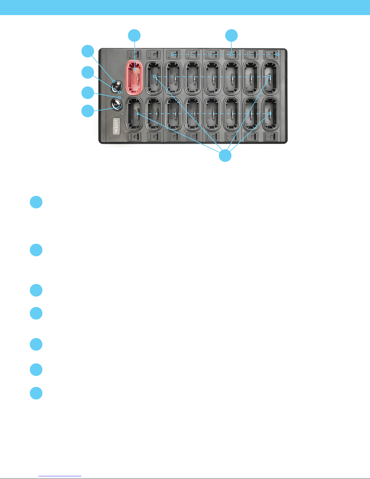
Docking Station 16 Tray
The optional ListenTALK Docking Station 16 serves as convenient storage, programming
and charging station for ListenTALK Transceivers. The Docking Station makes it easy to
create a ListenTALK Group and perform other tasks.
Docking Station Case 16
The optional ListenTALK Docking Station Case serves as convenient storage,
programming and charging station and portable carrying case for ListenTALK
Transceivers. The Docking Station Case provides all of the features of the
Docking Station 16 Tray.
Accessories
ListenTALK accessories include an Intelligent Cable Management Unit for the Docking
Station 16 Tray, several headsets and an alkaline battery case. Note that ListenTALK
Transceivers may also be used with standard smart phone headsets.
ListenTALK Software Suite
Available for Windows PCs, the ListenTALK Software Suite makes it easy to pair
ListenTALKs to form ListenTALK Groups, check ListenTALK status and it includes
many advanced programming features. (See Page 21)