ViVitro Labs SuperPump AR Series User manual

Document No. 17476-C © ViVitro Labs Inc. 2018 Page 1 of 22
SuperPump System User Manual
AR Series

Document No. 17476-C © ViVitro Labs Inc. 2018 Page 2 of 22
SuperPump AR System User Manual
ViVitro Labs SuperPump AR series System
Designed and Distributed by ViVitro Labs Inc., BC, Canada
Disclaimer and Limitation of Responsibility
ViVitro Labs Inc. assumes no responsibility for any damage, loss, or claims which may result
from a failure to follow the instructions contained in this manual. Additionally, ViVitro Labs Inc.
assumes no responsibility as a result of direct or derived injury, data loss, system malfunction
which occurs at the fault of misuse, alternation of the system or incorrect application of use so
advised or directed by ViVitro Labs.
Copyright
Copyright© 2018 by ViVitro Labs Inc. All rights reserved.
Published by ViVitro Labs Inc. Victoria, British Columbia, Canada
No part of this publication may be reproduced, stored in a retrieval system or transmitted in any
form or by any means, electronic, mechanical, photocopying, recording, scanning or otherwise
without the prior written permission of the Publisher. Requests to the Publisher for permission
should be addressed to ViVitro Labs Inc., 455 Boleskine Rd., Victoria BC, V8Z 1E7, Canada, tel
(250) 388 3531, fax (250) 483 1975, e-mail: support@vivitrolabs.com.
Limit of Liability/Disclaimer of Warranty: While the publisher and author have used their best
efforts in preparing this document, they make no representation or warranties with respect to the
accuracy or completeness of the contents of this document and specifically disclaim any implied
warranties of merchantability or fitness for a particular purpose. No warranty may be created or
extended by sales representatives or written sales material. The advice and strategies
contained herein may not be suitable for your situation. Neither the Publisher nor author shall be
liable for any loss of profit or any other commercial damages, including but not limited to special,
incidental, consequential or other damages.
ViVitro Labs Inc.
455 Boleskine Rd
Victoria, BC,
V8Z 1E7,
Canada
phone 250 388 3531
email info@vivitrolabs.com

Document No. 17476-C © ViVitro Labs Inc. 2018 Page 3 of 22
SuperPump AR System User Manual
About ViVitro Labs
ViVitro Labs offers industry leading prosthetic heart valve test equipment and related testing and
consulting services. Since our formation in 1984, we have worked closely with our clients –
universities, medical device manufacturers and regulatory agencies –to support their research,
regulatory and production requirements.
Our vision is to empower our clients to complete world-leading research, develop high quality,
innovative products and ensure that they demonstrate regulatory compliance.
What we offer
ViVitro Labs’ respected clients come from all over the world and include leaders in the
cardiovascular implant industry.
Academic Research
ViVitro Labs is a leading vendor to academic labs worldwide. Hundreds of citations refer to the
use of ViVitro Labs’ equipment. For example, the ViVitro Labs SuperPump has become a
worldwide standard for the generation of physiological pressure waveforms in academic
research applications.
Laboratory and Production Services
Almost every significant prosthetic valve company in the world has ViVitro Labs equipment in
their research laboratories. ViVitro Labs services include:
•Verification of Hydrodynamic Testing –ISO 5840:2005 Annex L
•Durability Testing –ISO 5840:2005 Annex M
•And other design specific testing

Document No. 17476-C © ViVitro Labs Inc. 2018 Page 4 of 22
SuperPump AR System User Manual
Contents
1Cautions and Warnings.................................................................................................. 5
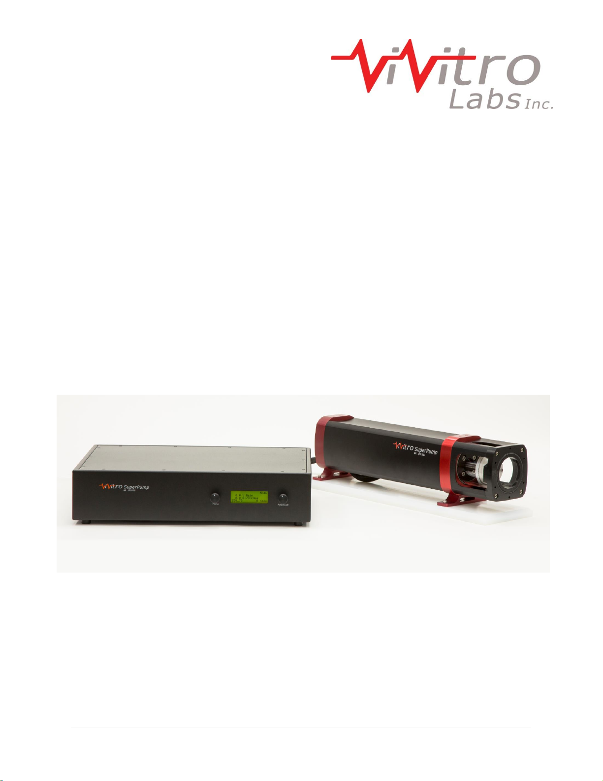
2About the SuperPump AR.............................................................................................. 6
2.1 Overview ................................................................................................................. 6
2.2 Features.................................................................................................................. 6
3Installation....................................................................................................................... 7
3.1 Unpacking the SuperPump...................................................................................... 7
3.2 Installing the SuperPump......................................................................................... 7
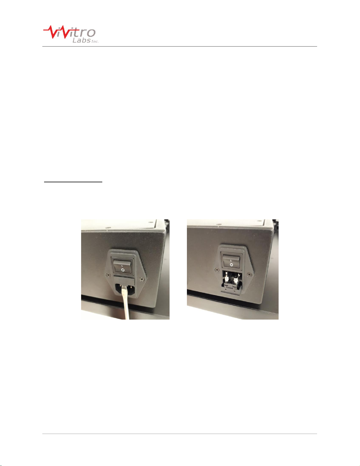
3.3 Electrical Requirements........................................................................................... 8
3.4 Fuses....................................................................................................................... 8
4Operating the SuperPump.............................................................................................. 9
4.1 Powering On the System......................................................................................... 9
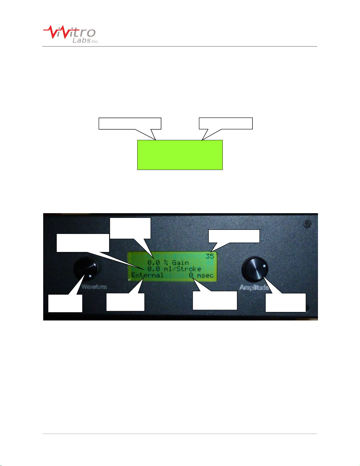
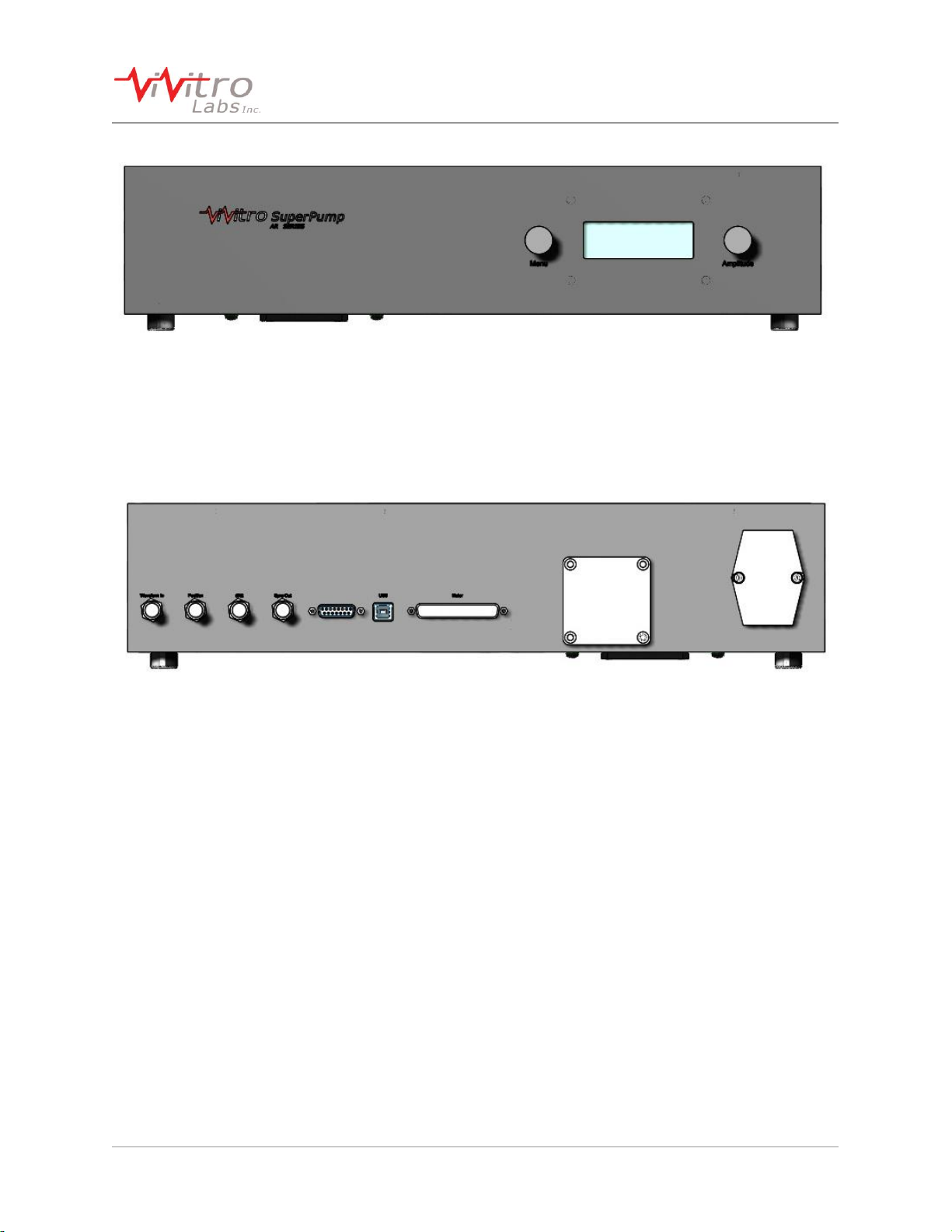
4.2 Front Panel.............................................................................................................10
4.3 Rear Panel..............................................................................................................10
4.4 Select Waveform ....................................................................................................11
4.5 Sync Pulse Delay....................................................................................................11
4.6 Cycle Count - Totalizer ...........................................................................................12
4.7 Pump Operation .....................................................................................................12
5Waveforms.....................................................................................................................13
5.1 Internal Waveforms.................................................................................................13
5.2 External Waveforms ...............................................................................................13
6Faults and Alarms..........................................................................................................14
6.1 Limit Switches.........................................................................................................14
6.2 Pump Error.............................................................................................................14
7Maintenance and Cleaning............................................................................................15
7.1 Cleaning .................................................................................................................15
7.2 Piston Seal Leakage...............................................................................................15
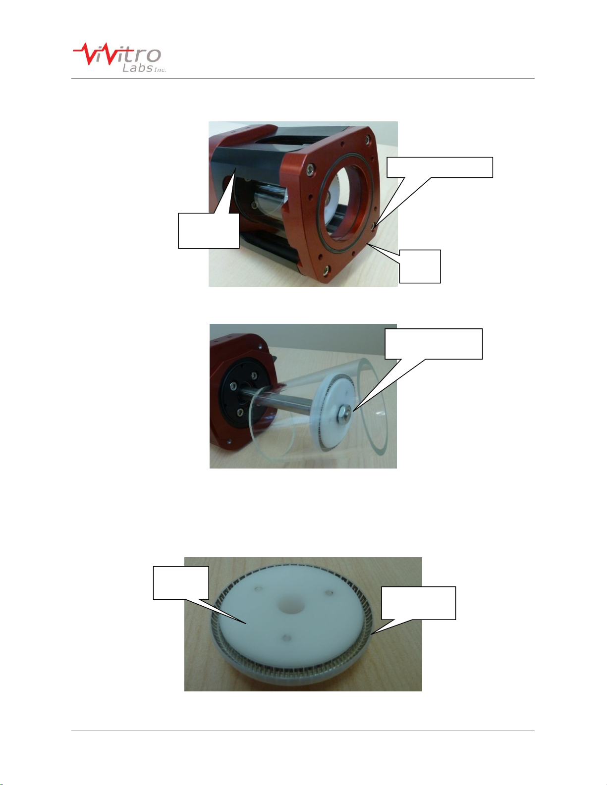
7.3 Piston Seal Replacement........................................................................................15
8Specifications ................................................................................................................19
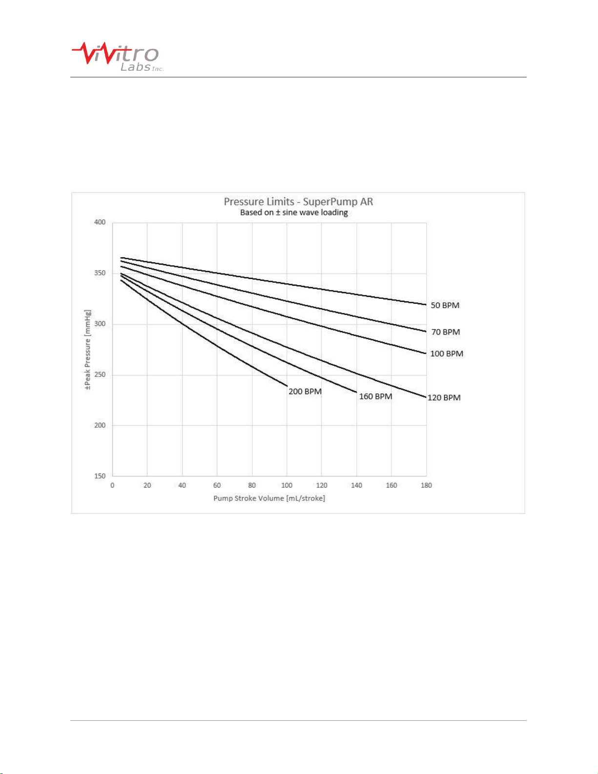
9Pressure Limits..............................................................................................................20
10 Mounting Details............................................................................................................22
10.1 Mounting Feet Bolt Pattern.....................................................................................22
10.2 Pump Cylinder Mounting Face Bolt Pattern ............................................................22

Document No. 17476-C © ViVitro Labs Inc. 2018 Page 5 of 22
SuperPump AR System User Manual
1 Cautions and Warnings
Read all of the instructions before operating the SuperPump.
•This instrument is intended for research use only and must be operated by trained lab
personnel.
•Do not mount the SuperPump vertically as this may lead to fluid ingress into the Pump
electronics.
•To ensure adequate cooling of the SuperPump Controller and Pump, place on a clean,
flat surface, and be sure that there is at least 10 cm (4 in) of clearance around each side
of the Controller and motor end of the Pump. Make sure that the fan vent is not blocked.
•Before plugging the instrument in, be sure that the correct fuses are installed. See
section 3.6.
•Always connect the power supply to a 3-prong, grounded AC outlet rated 4A, 110–240 V
using the AC power cord provided with the SuperPump. Do not use an adapter to an
ungrounded outlet.
•Electrical devices pose the risk of electric shock. To reduce the risk of shock, do not
open any covers that are fastened with screws.
•Do not allow fluids to enter the interior of the instrument. In the event of such a spill,
disconnect the power cable before cleaning up.
•Do not operate SuperPump in extreme humidity or in conditions that can create
condensation. Protect the instrument against dust and moisture, and avoid physical
shock and strong forces.
•Any accessory that is attached to the SuperPump must be tested to 375 mmHg
pressure.
•Double check any user generated waveforms installed on the Controller or input through
the Waveform In external input to ensure that they meet the waveform specification
criteria. See section 4.7.
•Clean the Controller and Pump exterior with a dry cloth. Disconnect power before
cleaning
•Use caution when moving the Controller and/or Pump. Disconnect power and Pump
cable before moving the system to a new location.
•Do not use the SuperPump system if there is evidence of physical damage or if the
system has been dropped or subject to impact.
•Do not attempt to service the product beyond what has been described in this manual.
All other servicing should be referred to qualified service personnel.

Document No. 17476-C © ViVitro Labs Inc. 2018 Page 6 of 22
SuperPump AR System User Manual
2 About the SuperPump AR
2.1 Overview
The ViVitro SuperPump is a digitally controlled hydraulic piston pulsatile Pump that creates
physiological cardiac flows. Unsurpassed in reliability, functionality, and versatility, the AR
Series digital technology provides maximum control with precision accuracy. The SuperPump
works with ViVitro or independently produced accessories to create reliable cardiac flows for
any type of cardiovascular device.
The ViVitro SuperPump is used in numerous studies throughout the world. Visit the Citation
Database on vivitrolabs.com for the current list of applications and articles.
The SuperPump provides maximum operator control with precision accuracy. The Pump can be
controlled by preconfigured waveforms or by customizable ViVitest software input.
2.2 Features
The SuperPump AR series from ViVitro Labs Inc. features include:
Piston-in-cylinder Pump head design
Digital motor with high torque to inertia ratio for smooth and reliable functionality
Controller with variable amplitude and internal storage for 5 waveforms
Position and velocity monitoring
Made with materials that are compatible with most sterilization and testing solutions
Arrhythmia and wave train function with ViVitest software
Proven history of reliability

Document No. 17476-C © ViVitro Labs Inc. 2018 Page 7 of 22
SuperPump AR System User Manual
3 Installation
The SuperPump System has several steps to the main mechanical sub-assemblies, and a few
steps for the electrical components installation/configuration.
NOTE: It is critical for the assembly steps to be followed in order to assure successful
operation.
3.1 Unpacking the SuperPump
The SuperPump AR arrives in 2 containers; a wooden shipping crate for the Pump and a
cardboard container for the Controller. Inspect the shipping containers for external damage.
Retain the shipping carton and packing materials for possible re-shipment. Inspect the system
components for damage. If there is evidence of damage contact the carrier, initiate a damage
claim, and inform ViVitro Labs.
The SuperPump arrives pre-assembled with the following parts:
Mounting base
Linear Actuator with Cable
Actuator Extension Cable
SuperPump Controller
3.2 Installing the SuperPump
The SuperPump is supplied mounted to a rigid plastic base for use on a bench top. Optionally
the Pump may be mounted directly to a structure or test apparatus using #10-32 fasteners
through the mounting feet of the Pump. See bolt pattern layout in section 10.
WARNING: Any accessory that is attached to the SuperPump must be tested to 375 mmHg
pressure.
The SuperPump must be mounted horizontally. The back side of the Pump cylinder is provided
with a drain; however vertical mounting of the Pump can result in water entering the ball
screw/motor causing an electrical hazard.
The Controller should be located away from the Pump to avoid any water or test fluid. An
extension cable is provided to allow extra separation if required.
It is recommended that the Pump act on the test fluid through a membrane to maintain isolation
between working and test fluid. The piston should not be directly exposed to blood analog
solution or saline. Distilled water is recommended as the working fluid in contact with the piston.
When connecting the Controller to other equipment such as computers or a signal generator
ensure all equipment is on the same ground. Ground loops can cause noise or signal offsets
which will result in a noisy or inconsistent waveform. Any test setup should be validated by
running known samples before testing.

Document No. 17476-C © ViVitro Labs Inc. 2018 Page 8 of 22
SuperPump AR System User Manual
3.3 Electrical Requirements
Use only the power cord supplied with your SuperPump. The Controller must be plugged into a
grounded outlet rated for 300W. The system can operate with 90-240 VAC / 50-60 Hz power.
All equipment be checked for correct fuse ratings prior to use. See section 3.4.
3.4 Fuses
When using the ViVitro Labs SuperPump with 220V –240V power, the Controller fuses must be
replaced with the 2A fuses provided.
If the Controller is being used with 100V –127V power, the 4A fuses shipped in the device must
be used.
Fuse Requirements:
100V –127V Power: 2x 4A Fuses (included in Controller)
220V –240V Power: 2x 2A Fuses (shipped in SuperPump Crate)
Contact ViVitro Labs if you require replacement fuses.

Document No. 17476-C © ViVitro Labs Inc. 2018 Page 9 of 22
SuperPump AR System User Manual
4 Operating the SuperPump
4.1 Powering On the System
Turn on the power switch on the back of the Controller. The screen on the front of the Controller
will light up and indicate that it is Initializing. It will then automatically begin a Homing Pump
sequence.
V 3.0.5 2014/02/20
0.0 % Gain
0.0 ml/Stroke
Initializing
After automatically homing the Pump, the screen will appear as below. The most recently used
waveform source will appear in the Current Waveform section.
If the Pump is not connected to the Controller when the system is powered on, Pump Error will
be displayed. Power off the Controller, connect the Pump cable, and power the Controller on to
clear the error.
Firmware Version
Cycle Counter
Current
Waveform
Sync Output
Delay
Current
Amplitude
Current Stroke
Volume
Firmware Date
Menu
Dial
Amplitude
Dial

Document No. 17476-C © ViVitro Labs Inc. 2018 Page 10 of 22
SuperPump AR System User Manual
4.2 Front Panel
The front panel consists of 2 controls and the display. The controls are rotary encoders with
push switches. To the left of the display is the Menu dial which allows scrolling by turning the
dial and selection by pressing the dial. To the right of the display is the Amplitude dial which
adjusts the amplitude of the output waveform and starts, pauses and stops the Pump by
pressing the dial.
4.3 Rear Panel
The rear panel contains all of the connectors. From left to right:
Waveform In: BNC connector used when an external signal is used as the waveform
Position: BNC connector analog output signal for the piston position
dl/dt: BNC connector analog output signal proportional to instantaneous flow rate
Sync Out: BNC connector 5V TTL signal triggered at the rising zero crossing of the
waveform. The timing of the signal can be adjusted to any point in the waveform
Troubleshooting port : no user accessible functions
USB: For uploading custom waveforms created using ViVigen software or for use with
ViVitest when the SuperPump is used as part of the Pulse Duplicator
Motor: Cable connection to the Pump
Cooling vent
Power input: Power cord connector, fuse holder and main power on/off

Document No. 17476-C © ViVitro Labs Inc. 2018 Page 11 of 22
SuperPump AR System User Manual
4.4 Select Waveform
Press the Menu Selector Dial. Turn the Menu dial until “1 Waveform Source” appears as shown
below.
0
0.0 % Gain
0.0 ml/Stroke
1 Waveform Source
While the message Waveform Source is on the screen, press the dial again. The screen will
now indicate the most recently used waveform source.
0
0.0 % Gain
0.0 ml/Stroke
Wfm: External
If the current waveform source is desired press the dial again to escape the waveform selector.
If a stored waveform is desired turn the dial clockwise and press the dial to select the displayed
waveform.
Refer to section 4.7 for more details on waveform options.
0
0.0 % Gain
0.0 ml/Stroke
Wfm: PHYSIO_70
4.5 Sync Pulse Delay
The Sync Pulse is a +5V signal with 10ms duration which can be used for synchronizing and
triggering equipment such as high speed cameras.
Press the Menu Selector Dial. Turn the menu dial until “2 Sync Pulse Delay”is on the screen,
press the dial again. The screen will now indicate the current sync delay in msec.
0
0.0 % Gain
0.0 ml/Stroke
2 Sync Pulse Delay
To adjust the delay turn the dial until the correct delay is displayed and then press the dial. The
Sync Pulse Delay may be adjusted from 0 to 2000ms. A 0ms delay will trigger as the piston
crosses forward across the home position.

Document No. 17476-C © ViVitro Labs Inc. 2018 Page 12 of 22
SuperPump AR System User Manual
4.6 Cycle Count - Totalizer
Press the Menu Selector Dial. Turn the menu dial until “3 Totalizer”is on the screen, press the
dial again.
34
0.0 % Gain
0.0 ml/Stroke
3 Totalizer
To adjust the counter turn the dial until the desired value is displayed and then press the dial.
0
0.0 % Gain
0.0 ml/Stroke
3 Totalizer
4.7 Pump Operation
0
0.0 % Gain
0.0 ml/Stroke
PHYSIO_70 0 msec
Turn the Amplitude dial until the desired stroke volume is reached. For example:
51
40.7 % Gain
73.4 ml/Stroke
PHYSIO_70 0 msec
To pause or stop the Pump either press the Amplitude dial. Once the Amplitude dial has been
pressed once, the system is paused and the following screen will be displayed:
57
0.0 % Gain
73.4 ml/Stroke
<-Resume Stop->
Pressing the Menu dial (left) will resume Pumping at the displayed ml/Stroke stroke volume.
Pressing the Amplitude dial (right) will home the Pump.

Document No. 17476-C © ViVitro Labs Inc. 2018 Page 13 of 22
SuperPump AR System User Manual
5 Waveforms
The SuperPump may be operated using either:
a) Internal waveforms stored in the Controller memory
b) External waveforms which are generated by an external device and input through the
Waveform In BNC connector on the Controller
5.1 Internal Waveforms
Internally stored waveforms may be modified or replaced using ViVigen software. The
SuperPump allows for storage of up to 5 unique internal waveforms in the Controller memory.
Custom waveforms can be generated and stored on the Controller. See the ViVigen user
manual (document no. 17474) for further information.
5.2 External Waveforms
A waveform generated by an external device may be used to operate the SuperPump. External
waveforms are input into the Controller by connecting a BNC cable from the waveform source to
the Waveform In port on the back of the SuperPump Controller (see section 4.3). The
Waveform Source must be set to External (see section 4.4) for the SuperPump to operate using
the external input.
The external waveform must conform to the following specifications:
Amplitude: ±5.0 V maximum. Any waveform that exceeds this amplitude will not be
accurately represented in the Pump movement.
Rate [Frequency]: 3 bpm (beats per minute) minimum to 200 bpm maximum. [0.05 Hz to
3.33 Hz]
NOTE:Do not input waveforms with frequency greater than the listed maximum (200 BPM).
The waveform should be centered about 0 V (ground), without D.C. offset, unless offset
is intended for recreating a particular wave shape. The peak-to-peak limits with offset
must still remain within ±5.0 V relative to ground.
Noise and Distortion: both noise and distortion will affect the accuracy of the Pump
movement; therefore the signal source should be clean, with THD+N (total harmonic
distortion and noise) below 5%.
NOTE:The maximum velocity of the piston is limited to approximately 60mm/sec. As amplitude
and frequency are increased the velocity will also increase. If the Pump cannot match
the desired waveform a Pump error will result. In this case either the maximum slope of
the waveform must be reduced or the frequency or amplitude must be reduced.

Document No. 17476-C © ViVitro Labs Inc. 2018 Page 14 of 22
SuperPump AR System User Manual
6 Faults and Alarms
6.1 Limit Switches
The SuperPump actuator contains a factory-set limit sensors for the maximum push and pull
stroke. In case of a Limit reached alarm, press the Amplitude dial to clear the alarm and home
the Pump.
82
0.0 % Gain
180.0 ml/Stroke
Limit reached!
6.2 Pump Error
If the Controller loses communication with the Pump or if the Pump is unable to move, a Pump
error message will appear. If this occurs,
1. Turn off the system
2. Check that the cables are properly connected
3. Ensure that the Pump is free of mechanical interference and damage
4. Turn the Controller on and allow it to initialize normally
5. If the alarm persists, contact ViVitro Labs
93
0.0 % Gain
0.0 ml/Stroke
Pump Error!
See section 9 for information on the SuperPump AR pressure limits.

Document No. 17476-C © ViVitro Labs Inc. 2018 Page 15 of 22
SuperPump AR System User Manual
7 Maintenance and Cleaning
7.1 Cleaning
The outer surfaces of the SuperPump and Controller should be cleaned with a dry cloth only.
The Pump cylinder may be flushed with distilled water or, in the case of contamination, mild
detergent and water followed by rinsing with distilled water.
Periodic replacement of the fluid is recommended. If any bio-growth is observed, the system
must be drained and cleaned as directed above.
To prevent bio-growth in the system, a biocide such as ProClin or Cosmocil CQ may be used in
the test fluid per the manufacturer’s recommendations.
7.2 Piston Seal Leakage
Periodically, the glass cylinder should be inspected to check for signs of water leaking past the
piston seal. During the initial stages of piston leakage, a slight wipe mark of fluid may be seen
on the inside of the cylinder. Excessive leakage may lead to fluid ingress into the Pump
electronics, causing damage to the system and electrical hazard.
See section 7.3 for directions on replacing the piston seal.
7.3 Piston Seal Replacement
If leakage behind the piston seal is noted, the Piston Seal (SPM043.1) should be replaced. In
the following procedure, part numbers are given in parentheses should replacements need to be
purchased. The Piston Seal (SPM043.1) is replaced as instructed below.
1. Remove the three #6-32 x ¾” screws located on the front of the piston and remove the
SuperPump Piston Cap (09533) and O-Ring (09534).
#6-32 x ¾” SHCS
Piston Cap

Document No. 17476-C © ViVitro Labs Inc. 2018 Page 16 of 22
SuperPump AR System User Manual
2. Remove the four ¼”-20 x 4.5” screws (08980) and End Cap (08975) from the front of the
Pump head.
3. Remove the Short Extrusion (08981) and end cap from the Pump assembly.
4. Carefully remove the glass cylinder from the piston.
CAUTION: DURING THIS STEP BE CAREFUL WHEN HANDLING THE GLASS CYLINDER AS THE EDGES MAY
BE SHARP.
5. Remove the M10 nut and lockwasher from the front of the piston.
6. Remove the SuperPump Piston (09532) from the rod end.
¼”-20 x 4.5”
SHCS
Short
Extrusion
M10 Nut and
Lock Washer
End
Cap
Piston Seal
(SPM043.1)
Piston
(09532)

Document No. 17476-C © ViVitro Labs Inc. 2018 Page 17 of 22
SuperPump AR System User Manual
7. Locate the small hole near the outer edge of the Piston (09532). Holding the piston
firmly, push the piston seal off with a small hex key. Be sure not to scratch or damage
the piston sealing surface during this step.
8. Check the sealing surface of the piston for scratches that are either visible or can be felt
with a fingernail. Ensuring the orientation is correct, snap the piston seal onto the piston
carefully by hand.
9. Clean any dust and debris from the glass cylinder. Apply two layers of electrical tape on
either side of one end of the glass cylinder as shown below.
10. Push the piston into the glass cylinder (SPM042) using the two layers tape as a glide
point. Remove the electrical tape from the Glass Cylinder (SPM042).
11. Slide rod end into the SuperPump Piston (09532). Fasten in place with a M10 Lock
Washer (09538), Loctite, and the nut from the rod end. Ensure the glass cylinder does
not bump against the cylinder rod.
12. Push the Glass Cylinder (SPM042) onto the Pump. Ensure that the piston does not
come close to the sharp edge of the glass cylinder.
Piston sealing
surface
Push here
M10 Nut and
Lock Washer

Document No. 17476-C © ViVitro Labs Inc. 2018 Page 18 of 22
SuperPump AR System User Manual
13. Place the Short Extrusion (08981) onto the Pump. Orient as shown below.
14. Push O-Ring-235 (SPM072) into the groove on the outside face of End Cap (08975).
15. Push O-Ring-335 (10084) into the groove on the inside face of End Cap (08975).
16. Fasten the End Cap (08975) onto the Pump head with four ¼”-20 x 4.5” SHCS (08980).
Take care not to chip the edge of the glass with the aluminum parts. Tighten the
fasteners gradually to prevent uneven stress on the glass cylinder. Compress the sides
of the Short Extrusion (08981) while tightening so that the sides sit flush with the end
cap faces.
17. Check for damage on O-Ring (09534). Press the o-ring into the recess of the
SuperPump Piston Cap (09533) (if not already inserted).
18. Fasten the SuperPump Piston Cap (09533) to the SuperPump Piston with three #6-32 x
¾” SHCS (HCM079).
The SuperPump is now ready to resume operation.
O-ring
(SPM072)
¼”-20 x 4.5”
SHCS
Short Extrusion (08981)
**Note orientation**
Outside Face
Long flat
section
Inside Face
O-ring
(10084)

Document No. 17476-C © ViVitro Labs Inc. 2018 Page 19 of 22
SuperPump AR System User Manual
8 Specifications
SuperPump AR
Pump bore diameter
Nominal 69.85mm (2.750”)
Pump stroke
0-50mm (±25mm)
Displacement
0-180mL/stroke
Piston Area
38.32 cm2
Rate
3 to 200 beats per minute
Maximum pressure
375 mmHg
Waveform Accuracy
<4% of Stroke Volume at 70 BPM
(±3.0 mL @ 75 mL/stroke)
<5% of Stroke Volume at 200 BPM
(±3.8 mL @ 75 mL/stroke)
Inputs
External Waveform
± 5 V
0.05 Hz to 3.33 Hz
(3 to 200 beats per minute)
Outputs
Position
-5 to 5 V (200mV/mm)
dl/dt
-5 to 5 V (539 ml/s/V)
Sync Pulse
+5V signal for 10ms duration
Adjustable from 0 to 2000ms delay
LE at rising zero crossing
Electrical Requirements
Voltage
90-240 VAC / 50-60Hz
Power
Max 300W
Dimensions
Controller
11 x 48 x 33 cm
Pump
15 x 55 x 17 cm
Environmental
Operating Temperature
10 to 35ºC
Operating Humidity
15 to 75%
Operating pressure (elevation)
70-106 kPa
Shipping/Storage Temperature
-20 to 50 ºC
Shipping/Storage Humidity
15 to 95%
No restriction on pressure during shipping/storage

Document No. 17476-C © ViVitro Labs Inc. 2018 Page 20 of 22
SuperPump AR System User Manual
9 Pressure Limits
The SuperPump pressure limit will depend on several variables, such as the beat rate, stroke
volume and pressure profile generated by the system. As a guideline, refer to the plot below
showing the pressure limits of the SuperPump AR based on a 50% sine wave with pressure
loading centered on 0mmHg (i.e. the Pump generating both positive and negative peak
pressures each cycle). Actual peak pressures that the system can produce will vary depending
on application.
The SuperPump AR motor Controller uses a current limit to prevent any damage to the motor or
actuator. If the system is over-pressurized, the current output to the motor will be regulated
resulting in the stroke volume being limited.
There are two ways to determine if the pressure limit is reached. This will depend on whether
the SuperPump has reached the instantaneous current limit, or the continuous current limit.
•If the instantaneous current limit is reached, the Stroke Volume [mL/stroke] displayed on
the Controller screen will stop increasing even though the percent gain [% Gain] value
continues to increase while turning the Amplitude dial.
•If the continuous current limit is reached, the Stroke Volume [mL/stroke] displayed on the
Controller screen will begin to drop after a short period of operation. This will be
accompanied with a noticeable drop in peak pressure as well as a ‘clipping’ of the peaks
of the dl/dt signal from the Controller.
Table of contents
Popular Water Pump manuals by other brands

ITT
ITT Goulds Pumps ICP Installation, operation and maintenance instructions

Water Process Solutions
Water Process Solutions Encore 700 Operation & maintenance manual

ITT
ITT Z6 Series Installation and operating instructions

Norco
Norco 910052A instruction sheet

Liberty Pumps
Liberty Pumps LSG202A installation manual

BRÖTJE
BRÖTJE HEP 25-180-10 installation instructions

Ilmvac
Ilmvac MP 601 E Operation manual

Wilo
Wilo Wilo-Drain TS Installation and operating instructions

PHCC
PHCC ST1033 Instruction manual & safety warnings

EINHELL
EINHELL GE-SP 18 LL Li Original operating instructions

Edelbrock
Edelbrock For Small Blaock Chevrolet V6&V8&V9 8882 General instructions

Bartels Mikrotechnik
Bartels Mikrotechnik mp6 operating manual