Vivo Link VL120013 User manual
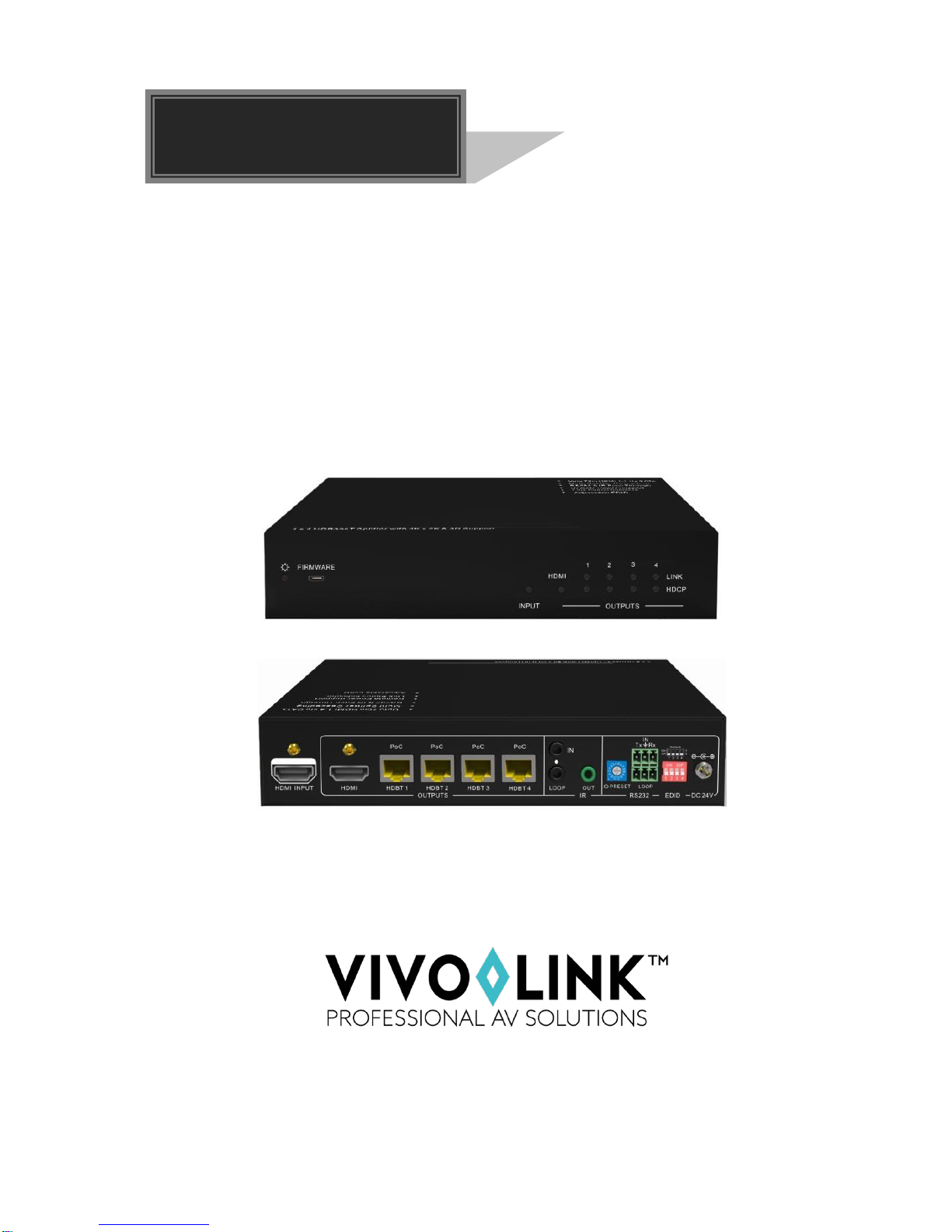
VL120013
4K HDBT Splitter 1x4 with PoC
User Manual
1

4K HDBT Splitter 1x4 with PoC
SAFETY PRECAUTIONS
To insure the best from the product, please read all instructions carefully before using
the device. Save this manual for further reference.
Unpack the equipment carefully and save the original box and packing material for
possible future shipment
Follow basic safety precautions to reduce the risk of fire, electrical shock and injury
to persons.
Do not dismantle the housing or modify the module. It may result in electrical shock
or burn.
Using supplies or parts not meeting the products’ specifications may cause damage,
deterioration or malfunction.
Refer all servicing to qualified service personnel.
To prevent fire or shock hazard, do not expose the unit to rain, moisture or install this
product near water.
Do not put any heavy items on the extension cable in case of extrusion.
Do not remove the housing of the device as opening or removing housing may
expose you to dangerous voltage or other hazards.
Install the device in a place with fine ventilation to avoid damage caused by
overheat.
Keep the module away from liquids.
Spillage into the housing may result in fire, electrical shock, or equipment damage. If
an object or liquid falls or spills on to the housing, unplug the module immediately.
Do not twist or pull by force ends of the optical cable. It can cause malfunction.
Do not use liquid or aerosol cleaners to clean this unit. Always unplug the power to
the device before cleaning.
Unplug the power cord when left unused for a long period of time.
Information on disposal for scrapped devices: do not burn or mix with general
household waste, please treat them as normal electrical wastes.
2

4K HDBT Splitter 1x4 with PoC
NOTICE:
1. Pictures shown in this manual are for reference only, different model and
specifications are subject to real product.
2. The item PoC is short for Power over Cable.
3. The receiver works with VL120013 can only be VL120001R.
4. The item “far-end”means the device (e.g. display device, 3rd party RS232 device
etc) connected with VL120001R.
3

4K HDBT Splitter 1x4 with PoC
Contents
1. Introduction.................................................................................................................5
1.1 Introduction to VL120013...................................................................................5
1.2 Features ............................................................................................................5
1.3 Package List......................................................................................................5
2.Panel Description.........................................................................................................6
2.1 Front Panel........................................................................................................6
2.2 Rear Panel.........................................................................................................7
3.System Connection......................................................................................................8
3.1 Usage Precautions............................................................................................8
3.2 System Diagram................................................................................................8
3.3 Connection Procedure.......................................................................................8
3.4 Cascade Connection .........................................................................................9
3.4.1 Cascade AV Signal..................................................................................9
3.4.2 Cascade Control Signal...........................................................................9
3.5 Twisted Pair Cable Connection..........................................................................10
4.Control Modes ..............................................................................................................11
4.1 IR Control ..........................................................................................................11
4.1.1 Control far-end device from local.............................................................11
4.1.2 Control local device from remote.............................................................12
4.2 RS232 Control...................................................................................................12
4.2.1 Installation/uninstallation of RS232 Control Software..............................13
4.2.2 Basic Settings..........................................................................................13
4.2.3 RS232 Communication Commands ........................................................14
4.3 EDID Management............................................................................................16
5.Specification ................................................................................................................17
5.1 Supported Input Video Formats.........................................................................17
6.Panel Drawing .............................................................................................................18
7.Troubleshooting & Maintenance ..................................................................................19
8.After-sales Service.......................................................................................................20
4

4K HDBT Splitter 1x4 with PoC
1. Introduction
1.1 Introduction to VL120013
VL120013 is an HDBT Splitter accepting 1 HDMI input and distributing to 4 HDBT
outputs, plus 1 HDMI local output. The HDMI output socket can be used to monitor local
devices or cascade with additional splitter.
VL120013 allows uncompressed 4K (max) HDMI, IR, and RS232 signals to be
transmitted over a single CAT5e/6/7 cable. It supports transmission of 4k signal up to
40m and 1080p signal up to 60m. If required, use the HDMI local output to cascade the
HDMI signal up to 4 times with additional S VL120013. VL120013 is also capable of
bi-directional IR control, RS232 control, EDID management and PoC.
VL120001R is recommended to utilize the full function of the HDBT outputs of this
device.
1.2 Features
Compliant with HDMI 1.4& 3D
Transmit 4k x 2k signal up to 40m and 1080p signal up to 60m
Support PoC
Support bi-directional IR control and cascade control
Support RS232 control and cascade control
Real-time display of working status via LED indicators
Support EDID configuration, 5 types in total
Support cascading via HDMI OUT, IR Loop and RS232 Loop
1.3 Package List
1 x VL120013
2 x Mounting ears (separate from VL120013)
8 x Screws
1 x 3.5mm Male-male Audio cable (used for IR signal cascade)
1 x RS232 cable (3-pin captive connector to DB9)
1 x RS232 cable (connect 2 3-pin captive connectors for cascading)
4 x Plastic cushions
1 x Power Cord
1 x Power Adapter (DC24V 2.71A)
1 x User Manual
Notes:Please confirm if the product and the accessories are all included, if not, please
contact with the dealers.
5
4K HDBT Splitter 1x4 with PoC
2. Panel Description
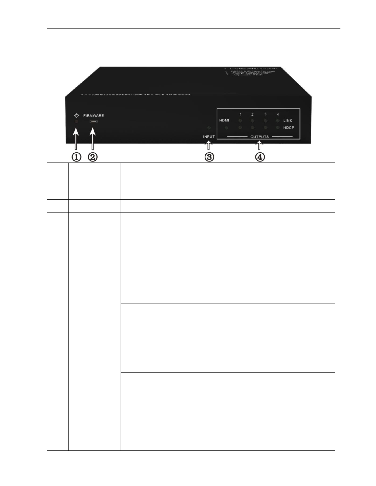
2.1 Front Panel
No.
Name
Description
①
Power
indicator
Illuminate red once powered on
②
FIRMWARE
USB port, used for firmware update.
③
INPUT
Iluminate green when there is input signal, remain off when
there is no input signal
④
OUTPUTS
HDMI:
illuminate green when the HDMI source signal is with HDCP
blink green when the HDMI source signal is without HDCP
turn off when there is no input HDMI signal
LINK: indicate linking status of the four HDBT sockets,
corresponding to the four HDBT sockets separately
illuminate green when the corresponding HDBT socket is
connected to VL120001R successfully
turn off when there is no VL120001R connected to the
correspongding socket.
HDCP: HDCP compliance indicator, correspondence with the
receivers connected to the four HDBT ports
illuminate green when the corresponding receiver is with
HDCP
blink green when the corresponding receiver is without
HDCP
remain off when there is no receiver connected to the
6
4K HDBT Splitter 1x4 with PoC
corresponding port
Note: Pictures shown in this manual are for reference only, different model and
specifications are subject to real product.
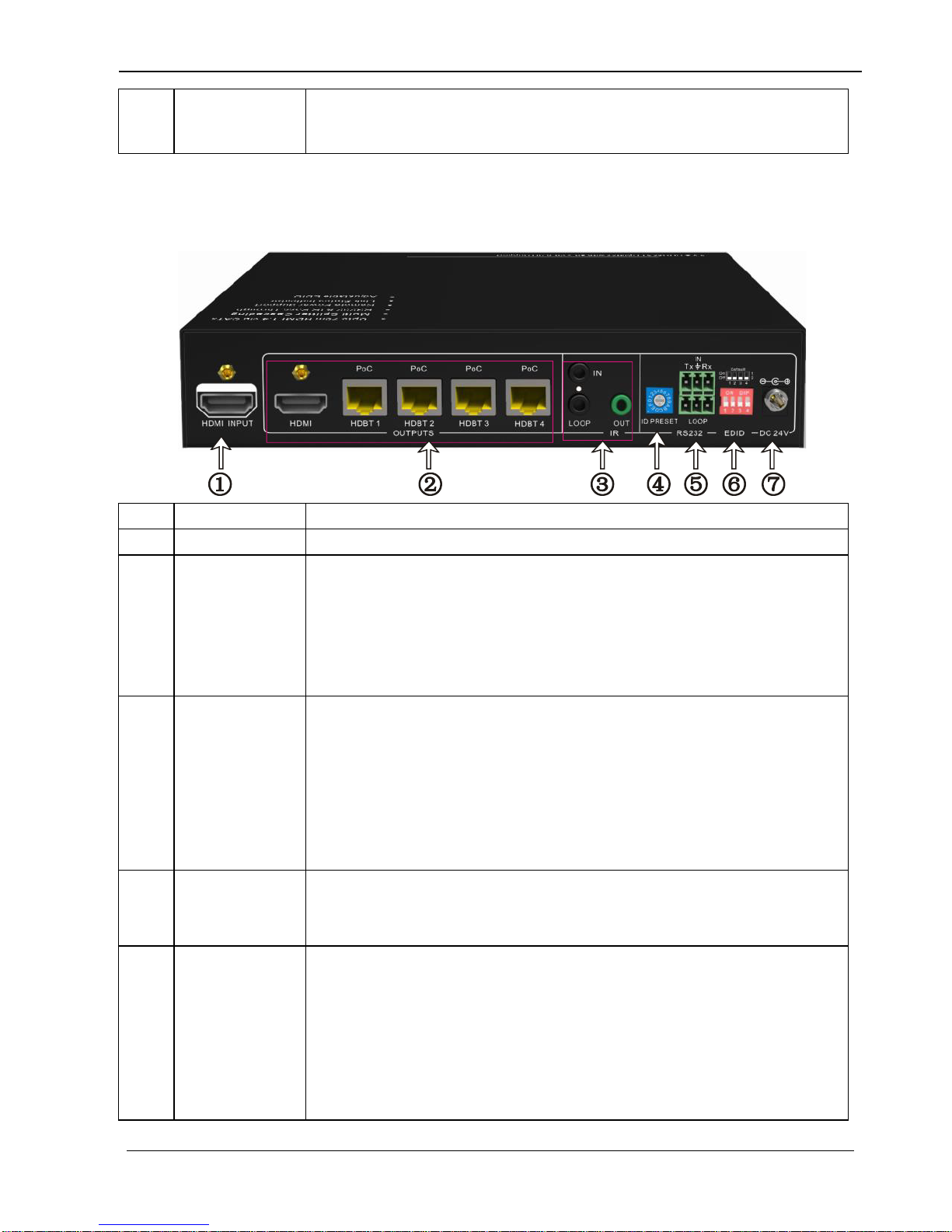
2.2 Rear Panel
No.
Name
Description
①
HDMI INPUT
Connect with HDMI source device such as DVD/ Blue-ray
②
OUTPUTS
HDMI: Connect to a HDMI display or cascade HDMI AV
signal to other displayers by connecting to the HDMI INPUT
port of the other VL120013
HDBT: HDBT output ports with PoC, 4 in total, connect with
HDBT receivers to transmit HDMI signal
③
IR
IN: Connect with IR Receiver to receive IR signal from IR
Emitter.
LOOP: Cascade IR control signal to another HDBT Splitter
by connecting to its IR IN socket
OUT: Connect with IR emitter to emit the IR signal received
from the receiver side.
④
ID PRESET
Assign ID for VL120013 to identify every unit, the value may
vary from 0~F.
After assigning ID, restart VL120013 for stable performance.
⑤
RS232
IN: connect with control device through 3-pin captive cable
LOOP: cascade RS232 control signal to another splitter by
connecting to its RS232 IN port
Note: Please set the communication protocol parameters
correctly, and send RS232 commands referring to instructions
in 3.6 RS232 Control.
7

4K HDBT Splitter 1x4 with PoC
⑥
EDID DIP
Switchers
4-pin EDID DIP switchers, “1”stands for “On”, “0”stands for
“Off”. Dial the switchers to change EDID data refering to the
explainations in 4.3 EDID Management.
⑦
DC 24V
Plug a 24V DC power adapter into this socket and tighten the
screw.
Note: Pictures shown in this manual are for reference only, different model and
specifications are subject to real product.
3. System Connection
3.1 Usage Precautions
1) System should be installed in a clean environment and has a prop temperature and
humidity.
2) All of the power switches, plugs, sockets and power cords should be insulated and
safe.
3) All devices should be connected before power on.
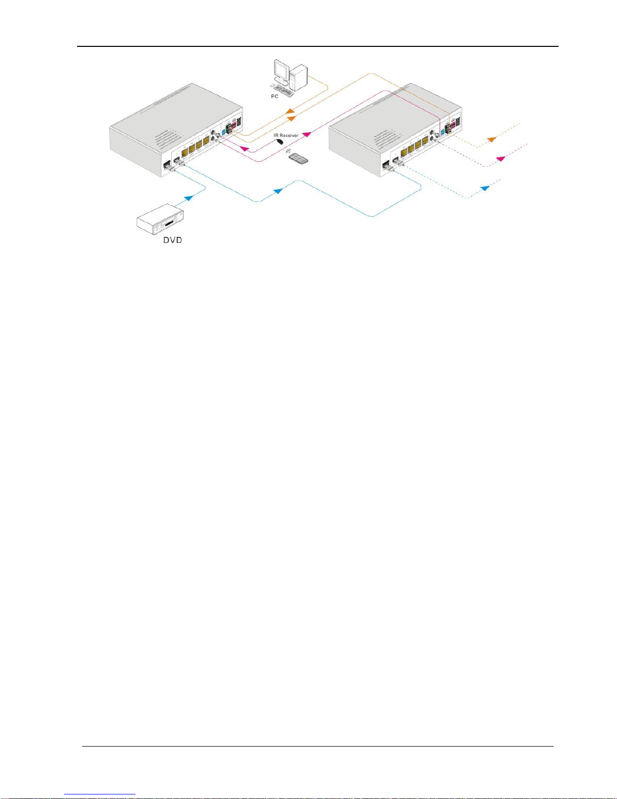
3.2 System Diagram
3.3 Connection Procedure
Step1.Connect a HDMI source device (e.g. Blue-ray DVD) to the HDMI INPUT socket
of VL120013 with HDMI cable.
Rs232
Control panel
DVD
HDTV
IR Emitter
HDTV
IR Emitter
HDTV
IR Emitter
HDTV
VL120001R
IR Emitter
HDTV
VL120001R
VL120001R
VL120013
8

4K HDBT Splitter 1x4 with PoC
Step2.Connect a HDMI display to HDMI OUTPUT socket of VL120013 with HDMI
cable.
Step3.Connect VL120001R(s) to HDBT output port(s) of VL120013 with twisted pair.
Step4.Connect control device (e.g. PC) to the RS232 IN port of VL120013.
If you want to cascade RS232 signal among several VL120013 through RS232
LOOP, connect the RS232 LOOP socket of one of them and the RS232 IN
socket of the next until all VL120013 have been connected.
Step5.Connect an IR Receiver to the IR IN port of VL120013 or VL120001R(s), and an
IR Emitter to the IR OUT port at the other end. The IR signal can be transmitted
bi-directionally between VL120013 and VL120001R(s).
If you want to cascade IR signal among several VL120013, connect the IR LOOP
socket of one of them and the IR IN socket of the next until all VL120013 have
been connected.
Step6.Connect a DC 24V power adapter to the power port of VL120013, VL120001R is
able to be energized by VL120013 with PoC solution.
3.4 Cascade Connection
3.4.1 Cascade AV Signal
HDMI source signal can be cascaded to several displayers via HDMI OUT/ IN.
Connect the HDMI OUT socket of the first VL120013 to HDMI IN socket of the next until
all VL120013 have been connected.
HDMI signals delivered within the first VL120013 are able to be outputted to other
connected VL120013 too.
3.4.2 Cascade Control Signal
VL120013
supports control cascading via IR LOOP/ RS232 LOOP to enable signal loop output.
Users can choose one or multiple cascade methods according to their specified needs.
Here is the cascade connection diagram:
9
4K HDBT Splitter 1x4 with PoC
Cascade through IR Loop
Connect the IR LOOP socket of the first VL120013 and the IR IN socket of the next
until all VL120013 have been connected.
Sending IR signals to the IR Receiver connected to the first VL120013 will control
all cascaded VL120013.
Cascade through RS232 Loop
Connect the RS232 LOOP socket of the first VL120013 and the RS232 IN socket
of the next until all VL120013 have been connected.
Sending RS232 commands will control all cascaded VL120013 synchronously.
Note: To identify VL120013 in cascading, please set a unique ID for each unit when the
cascade connection is done.
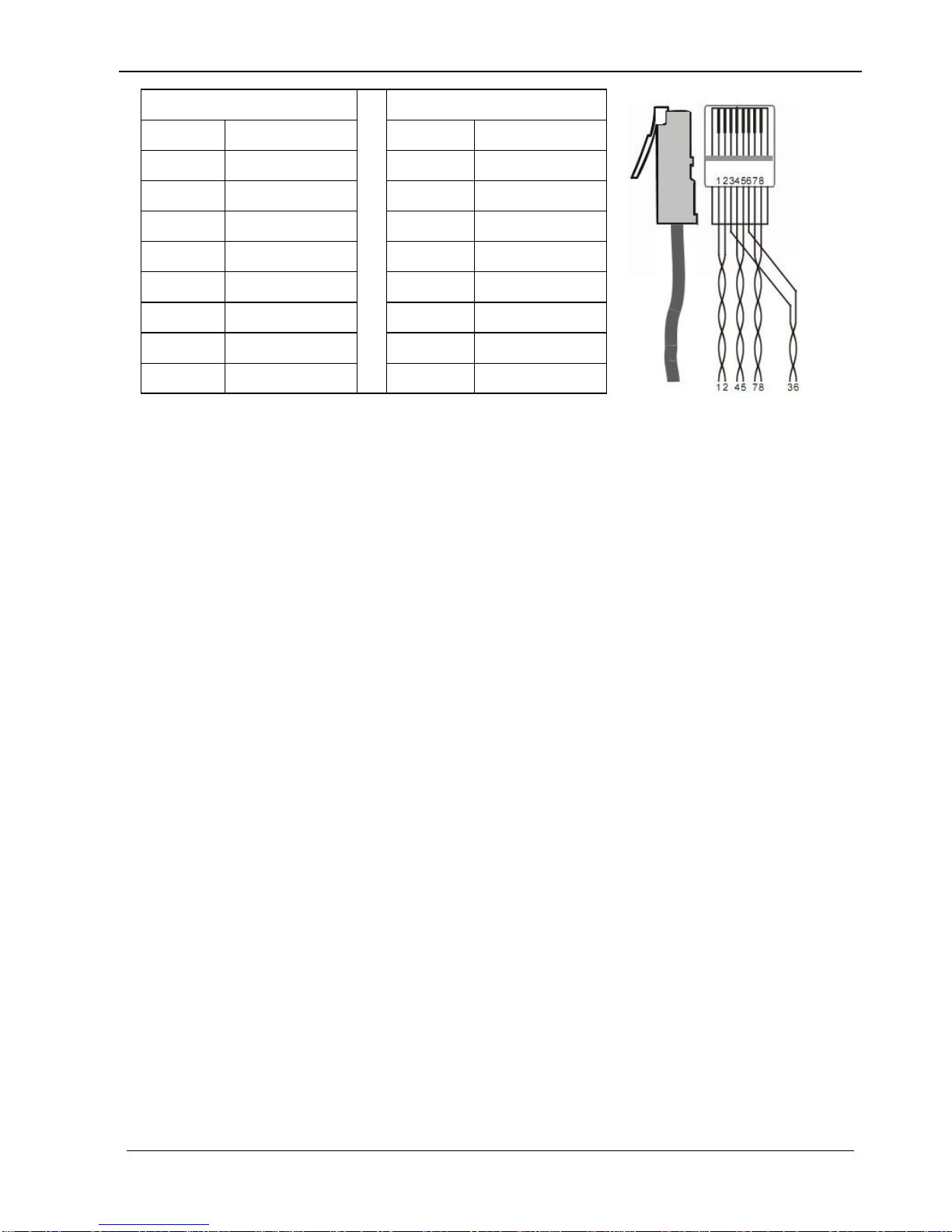
3.5 Twisted Pair Cable Connection
The twisted pair used in VL120001R MUST be a straight-through cable. The connectors
can be T568A or T568B, but both sides must be the same.
10
4K HDBT Splitter 1x4 with PoC
Note: Every pin in pure color groups with its half white pin.
4. System Control
VL120013 has a good application in various occasions, such as computer realm,
monitoring, conference room, big screen displaying, television education, command &
control center and smart home etc.
VL120013 can be controlled via IR, RS232 commands and EDID management.
4.1 IR Control
VL120013 provides with an IR IN port, the port support bi-directional transmission.
Connect an IR receiver to the IR IN port, users can control VL120013/ far-end device
from local or control local devices from remote via corresponding IR remote.
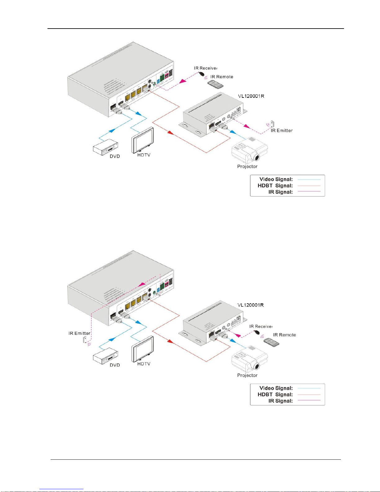
4.1.1 Control far-end device from local
Control VL120013 or far-end display device from local through corresponding IR
remote.
TIA/EIA T568A
TIA/EIA T568B
Pin
Cable color
Pin
Cable color
1
green white
1
orange white
2
green
2
orange
3
orange white
3
green white
4
blue
4
blue
5
blue white
5
blue white
6
orange
6
green
7
brown white
7
brown white
8
brown
8
brown
11
4K HDBT Splitter 1x4 with PoC
Figure 4- 1 Control far-end device from local
4.1.2 Control local device from remote
Control VL120013 or local displayer from remote via corresponding IR remote.
Figure 4- 2 Control local device from remote
4.2 RS232 Control
Connect the RS232 ports of VL120013 and VL120001R, VL120013 is capable to
12

4K HDBT Splitter 1x4 with PoC
control the third party (RS232 device) connected to VL120001R from local.
Note: VL120013 can only control third parties with designed baud rates, including 2400,
4800, 9600, 19200, 38400, 57600 and 115200.
4.2.1 Installation/uninstallation of RS232 Control Software
Installation Copy the control software file to the computer connected with
VL120013.
Uninstallation Delete all the control software files in corresponding file path.
4.2.2 Basic Settings
Firstly, connect VL120013 with an input device and an output device. Then, connect it
with a computer which is installed with RS232 control software. Double-click the
software icon to run this software.
Here we take the software CommWatch.exe as example. The icon is showed as below:
The interface of the control software is showed as below:
13

4K HDBT Splitter 1x4 with PoC
Please set the parameters of COM number, bound rate, data bit, stop bit and the parity
bit correctly, only then will you be able to send command in Command Sending Area.
Note: To control VL120013 via RS232 port, the communication protocol parameters
should be configured in the right manner: Baud rate: 9600; Data bit: 8; Stop bit: 1; Parity
bit: none.
4.2.3 RS232 Communication Commands
Command
Function
Feedback Example
EDIDUpgrade[x][y].
Upgrade EDID data via serial port;
[X]: unit ID, varies from 00~15;
[Y]: serial number of embedded
EDID, varies from 0~4 (correspond
to embedded EDID 1~5 separately).
Connect input source and keep
energized before sending this
command.
WAIT FOR EDID
FILE
[X][Y] [Q1],[Q2]$[Z]
Send command to several HDBT
Parameter Configuration area
Monitoring area, indicates
whether the command
sent works.
Command Sending area
Parameter Configuration area
Monitoring area, indicates
whether the command
sent works.
Command Sending area
14

4K HDBT Splitter 1x4 with PoC
Command
Function
Feedback Example
outputs port synchronously
[X]: unit ID, varies from 00~15;
[Y]: serial number of third party’s
baud rate, varies from 1~7;
[Q]: serial number of the HDBT
output port, varies from 1~4;
[Z]: command to be sent.
[X][Y][0]$[Z]
Send command to several HDBT
output synchronously;
[X]: unit ID, varies from 00~15;
[Y]: serial number of third party’s
baud rate, varies from 1~7;
[Z]: command to be sent.
OFF[X][Y1] ,[Y2],[Y3].
Switch off several outputs of a
splitter;
[X]: unit ID, varies from 00~15;
[Y]: serial number of output port, the
value can be 1~5 (1 corresponds to
the HDMI output port, 2~5
correspond to HDBT OUT 1~4
separately.)
OFF Y1, Y2, Y3
Y=1~5
OFF[X][0].
Switch off all the outputs of a splitter;
[X]: unit ID, varies from 00~15.
OFF All
ON[X][Y1],[Y2],[Y3].
Switch on several outputs of a
splitter;
[X]: unit ID, varies from 00~15;
[Y]: serial number of output port, the
value can be 1~5 (1 corresponds to
the HDMI output port, 2~5
correspond to HDBT OUT 1~4
separately.)
On Y1, Y2, Y3
Y=1~5
ON[X][0].
Switch on all outputs of a splitter;
[X]: unit ID, varies from 00~15.
On All
Note:
15
4K HDBT Splitter 1x4 with PoC
1. In above commands, “[”and “]” are symbols for easy reading and do not need to be
typed in actual operation.
2. Type in the complete commands including ending symbol “.”.
3. When the unit ID is changed, please reboot the unit before sending commands.
4. Load the desired EDID file to the RS232 control software after sending command
EDIDUpgrade[x][y]. , it will show “EDIDUpgrade success”after the upgrade is
completed.
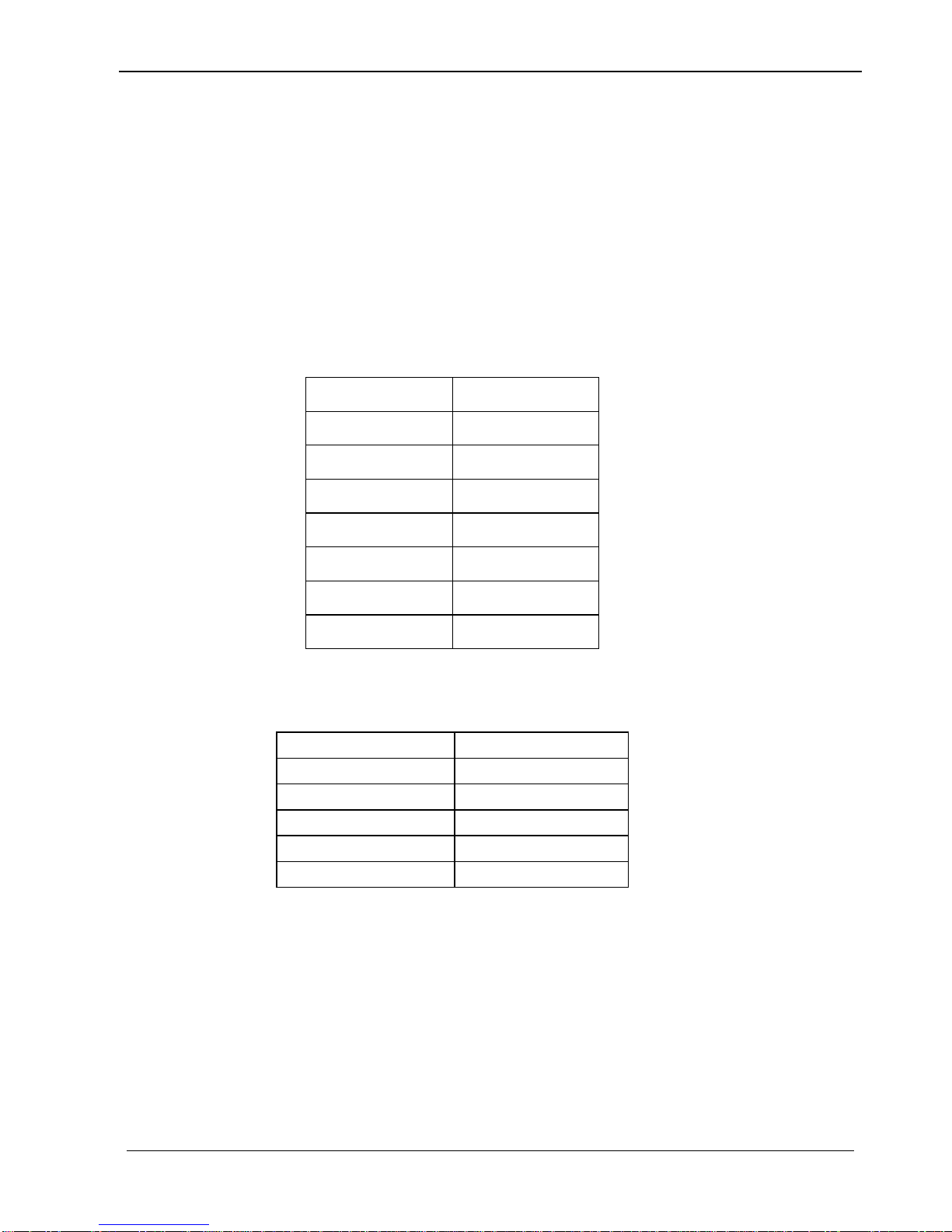
5. To control the third party via RS232 commands, users should type in the correct
serial number for the device’s baud rate in the command. Here is a list of the baud
rates and their serial numbers:
No.
Baud Rate
1
2400
2
4800
3
9600
4
19200
5
38400
6
57600
7
115200
4.3 EDID Management
VL120013 provides with a 4-pin EDID DIP switcher, “1”stands for “On”, “0”stands for
“Off”. Dial the switches to change EDID data refering to the following explainations:
Switcher Status
EDID information
0001
1080P 2D
0010
1080P 3D
0011
720P 2D
0100
720P 3D
0101
DVI 1920x1080
In factory default status (Status: 0000), VL120013 pass through the signals directly,
input& output device process the signal automatically.
EDID data supports upgrade via serial port. Send command EDIDUpgrade[x][y]. to
upgrade the 5 embedded EDID data separately.
16
4K HDBT Splitter 1x4 with PoC
5. Specification
Items
Description
Video Input/output
VESA and SMPTE 480p to 2160p(4K) With 3D
Bit depth: 16, 20, 24
Audio Input/output
All HDMI audio formats including Dolby D (TrueHD)/ DTS
(HD-Master Audio)/ PCM
Channel count: from 2-8 (2.0 to 7.1)
Sample rates: 32 kHz, 44.1 kHz, 48 kHz, 88.2 kHz, 96 kHz,
176.4 kHz and 192 kHz
Power Supply
DC24V 2.71A
HDBT
60m (196feet) with HDMI video, RS232 & IR control, PoC
supports VivoLink VL120001R
Control
RS232 & IR Full function pass though;
RS232 port ID selectable for cascading;
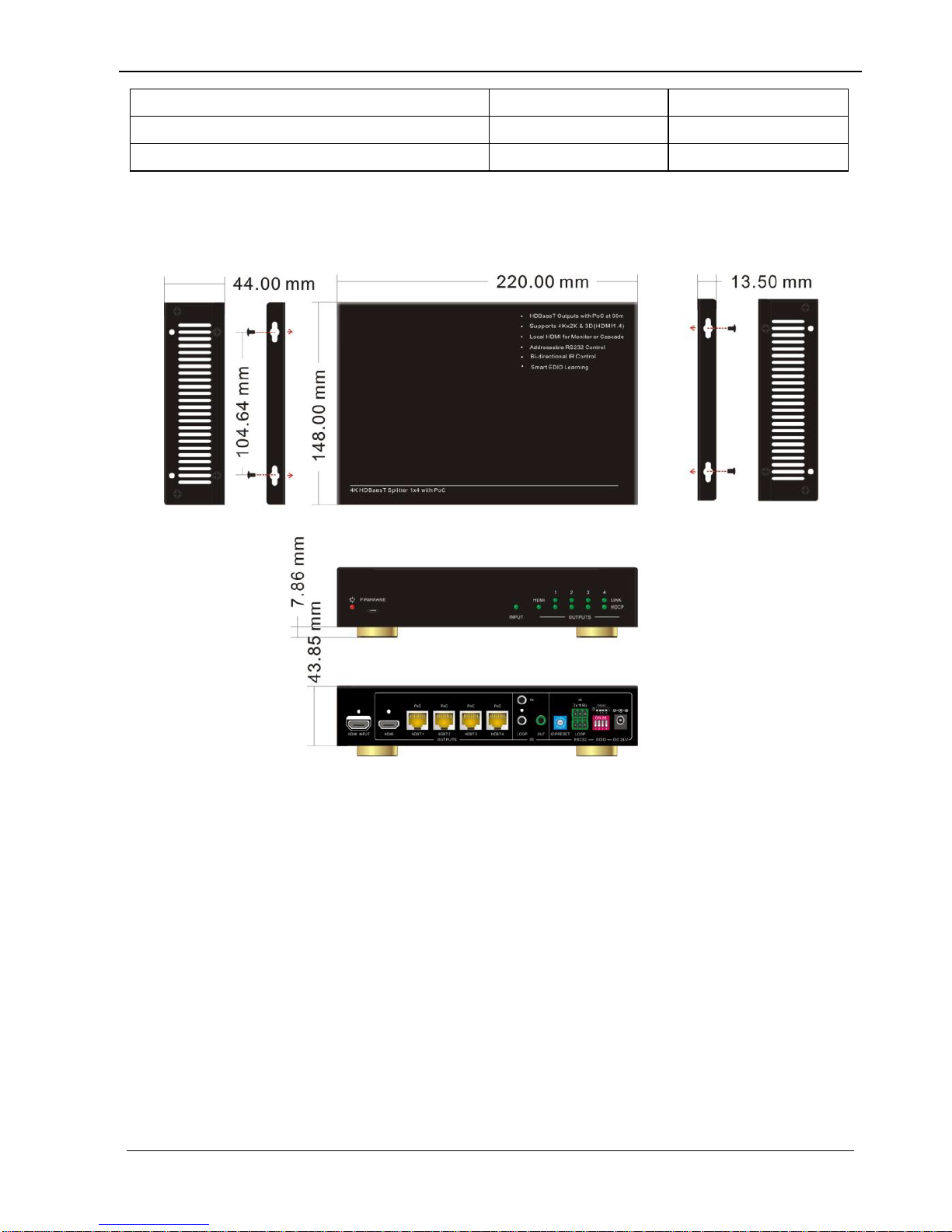
Dimensions
220 x 148 x 44mm (half rack wide)
Raw Materials
Aluminum chassis
Installation
Standard Rack size, provide removable ears for mounting
under table, or on wall
5.1 Supported Input Video Formats
Input Resolution
HDMI
DVI
720 x 480@60Hz
720 x 480I@30Hz
720 x 576@50Hz
720 x 576I@25Hz
1280 x720@50Hz
1280 x720@60Hz
1920 x 1080@25Hz
1920 x 1080@50Hz
1920 x 1080@60Hz
1920 x 1080I@25Hz
1920 x 1080I@30Hz
3840 x 2160@25Hz
17
4K HDBT Splitter 1x4 with PoC
3840 x 2160@30Hz
3840 x 2160@60Hz
1080P 3D@60Hz
Note: VL120013 supports 4k& 3D HDMI signals, please adopt quality HDMI cables
compliant with HDMI1.4 for better transmission when connecting 4K or 3D sources.
6. Panel Drawing
18

4K HDBT Splitter 1x4 with PoC
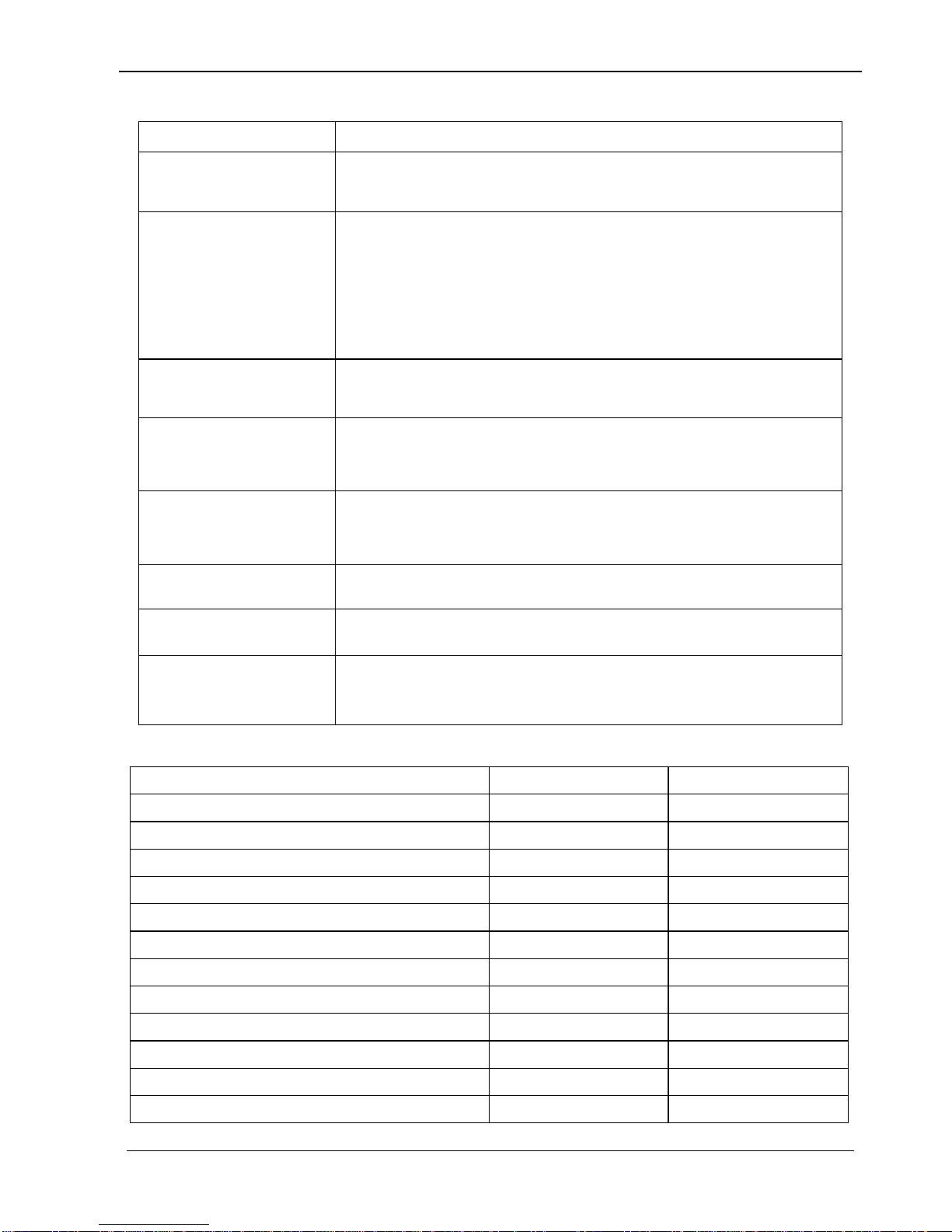
7. Troubleshooting & Maintenance
Problems
Causes
Solutions
Color losing or no video
signal output in HDMI
display
The connecting cables may
not be connected correctly
or it may be broken.
Check whether the cables
are connected correctly
and in working condition.
No HDMI signal output in
VL120013 while local
HDMI input is in normal
working state
Cannot control VL120013
by control device (e.g. a
PC) through RS232 port
Wrong RS232
communication parameters
Make sure the RS232
communication parameters
are correct.
VL120013 is broken
Send it to authorized
dealer for repairing.
Static becomes stronger
when connecting the video
connectors
Bad grounding
Check the grounding and
make sure it is connected
well.
If your problem persists after following the above troubleshooting steps, seek further
help from authorized dealer or our technical support.
19

4K HDBT Splitter 1x4 with PoC
8. After-sales Service
If there appear some problems when running VL120013, please check and deal with the
problems referring to this user manual. Any transport costs are borne by the users
during the warranty.
1) Product Limited Warranty: EET warrants that its products will be free from defects
in materials and workmanship for three years, which starts from the first day you
buy this product (The purchase invoice shall prevail).
Proof of purchase in the form of a bill of sale or receipted invoice which is evidence
that the unit is within the Warranty period must be presented to obtain warranty
service.
2) What the warranty does not cover (servicing available for a fee):
Warranty expiration.
Factory applied serial number has been altered or removed from the product.
Damage, deterioration or malfunction caused by:
Normal wear and tear
Use of supplies or parts not meeting our specifications
No certificate or invoice as the proof of warranty.
The product model showed on the warranty card does not match with the
model of the product for repairing or had been altered.
Damage caused by force majeure.
Any other causes which does not relate to a product defect
Delivery, installation or labor charges for installation or setup of the product
3) Technical Support: Email to our after-sales department or make a call, please
inform us the following information about your cases.
Product version and name.
Detailed failure situations.
The formation of the cases.
Remarks: For any questions or problems, please try to get help from your local
20
Table of contents
Other Vivo Link Cables And Connectors manuals


