Lincoln R 82206 Owner's manual

Page
Section - E35 - 17AA
Form 402140
SEPT - 2006
MODEL 82206
BARE REEL
SERIES “R”
OWNER/OPERATOR MANUAL
SPECIFICATIONS
Maximum working pressure 5000 psi.
Material Inlet 1/2” NPT (Female)
Material outlet 1/2” NPT (Female)
Sheave width 5-1/2”
Sheave diameter 19-1/4”
Drum diameter 12-3/4”
Overall width 8-1/4”
Overall height 22-1/2”
Overall depth 21”
Maximum hose capacities (including hang down):
1/4” I.D. Air/waler hose (SAE 100 R6) 50 ft.
1/4” I.D. Grease hose (SAE 100 R2) 50 ft.
3/8” ID. Air/water hose (SAE 100 R6) 50 ft.
3/8” I.D. Grease hose (SAE 100 R2) 50 ft.
1/2” ID. Air/water hose (SAE 100 R6) 50 ft.
1/2” ID. Oil hose (SAE 100 R3) 50 ft.
1/2” I.D. Grease hose (SAE 100 R2) 50 ft.
5/8” I.D. Oil hose (SAE 100 R1) 50 ft.
NOTE: Maximim hose capacilies are based on SAE specified hoses.
Exceeding these capacities voids warranty. Refer to DELIV-
ERY HOSE INSTALLATION for proper hose to reel assembly.
IMPORTANT
THIS HOSE REEL ROLLER OUTLET REQUIRES 3-5/8” BALL STOPS, MODELS 85515, 85516 AND 85517.
DO NOT USE MODELS 83515, 83517 AND B3517 (3” O.D.) BALL STOPS WITH THIS OUTLET.
DESCRIPTION
Model 82206 unit is a heavy duty lubreel designed for bus and
truck lubrication, or wherever extra heavy duty
construction and longer length delivery hose is required. The
reel can be installed as a single unit or in multiple
configurations.
Reel features include a reel latch that automatically locks at
desired positions as the hose is extended and releases with a
short pull on the hose.
OWNER/OPERATOR RESPONSIBILITY
It is the owner/operator’s responsibility to properly use and
maintain this equipment.
The instructions and warnings contained in this manual shall
be read and understood by the owner/operator prior to op-
erating this equipment.
If an owner/operator does not understand English, the con-
tents of this manual shall be explained in the owner/operator’s
native language to assure the owner/operator comprehends.
It is the owner/operator’s responsibility to maintain the legibility
of all warning and instruction labels.
The owner/operator shall retain this manual for future
reference to important warnings, operating and
maintenance instructions.

Page Number - 2 Form 402140
FAILURE TO HEED THE FOLLOWING WARNINGS INCLUDING MISUSE, OVER PRESSURIZING, MODIFYING PARTS,
USING INCOMPATIBLE CHEMICALS AND FLUIDS, OR USING WORN OR DAMAGED PARTS, MAY RESULT IN EQUIP-
MENT DAMAGE AND/OR SERIOUS PERSONAL INJURY, FIRE, EXPLOSION, OR PROPERTY DAMAGE.
· Do not exceed the stated maximum working pressure of the reel or of the lowest rated component in your system.
· Do not alter or modify any part of this equipment.
· Do not operate this equipment with combustible gas.
· Do not attempt to repair or disassemble the equipment while the system is pressurized.
· Make sure all fluid connections are securely tightened before using this equipment.
· Always read and follow the fluid manufacturer’s recommendations regarding fluid compatibility, and the use of protective
clothing and equipment.
· Check all equipment regularly and repair or replace worn or damaged parts immediately.
· Never point the dispensing valve at any part of the body or at another person.
· Never try to stop or deflect material from dispensing valve or leading connection or component with your hand or body.
· Always check equipment for proper operation before each use, making sure safety devices are in place and operating
properly.
· Always follow the pressure relief procedure after shutting off the pump, when checking or servicing any part of the system,
and when installing cleaning or changing any part of the system.
ASSEMBLY
Assemble reel as follows. Refer to SERVICE PARTS for part
numbers and location.
A. Assemble arbor and ratchet casting (237670) to sup-
port assembly (237656) with four hex head screws
(50014) and four hex nuts 51022).
B. Lubricate V-ring seal (237671) and place on arbor
and ratchet casting (237670) with lip facing away from
arbor ratchet.
C. Assemble power spring assembly (237672) onto
arbor and ratchet casting (237670) until spring
canister bottoms on arbors shoulder
D. Lubricate V-ring seal (237673) and assemble onto ar-
bor and ratchet casting (237670) with lip facing toward
spring canister.
E. Assemble axle (274835) to sheave assembly (237680)
with three nuts (51412).
F. Assemble axle and sheave assembly to reel by slid-
ing axle (274835) through bearings in the arbor and
ratchet casting (237670). Secure with washer (48217)
and TRU-ARC (68424). Shim as required using shims
(48385) between washer (48217) and arbor and
ratchet casting (237670) to eliminate axle end play.
G. Rotate sheave assembly (237680) and align six
mounting holes with mating holes in power spring
cannister (237672). Secure with five carriage bolts
(237738). carriage bolt (237739) and six nuts (51412).
NOTE:The carriage bolt (237739) is assembled in
hole adjacent to pawl pin.
H. Assemble roller outlet arm assembly (237690) on
bolts (50014) and secure using three nuts (51022).
I. Assemble roller outlet assembly (237692) to roller
outlet arm, assembly (237690) using (4) 50033 Hex
Head Screws and (4) 51304 Lock Nuts.
J. Assemble swivel assembly (274840) in axle (274835)
and tighten.
K. Assemble adapter assembly (273065) into swivel
assembly (274840) and secure with U-keeper
(15674).
L. Assemble outlet adapter (273212) into axle (274835).
Secure with U-keeper (15674).
M. Assemble hose clamp to sheave assembly (237680)
with carriage bolt (237738). Secure with nut (51412).
N. Assemble latch pawl (237683) to pawl pin on power
spring assembly (237672) and secure with washer
(48327) and TRU-ARC (66316).
O. Assemble extension spring (237695) to latch pawl
(237683) and carriage bolt (237739). Secure with
locknut (51304).

Page Number - 3
Form 402140
INSTALLATION
DELIVERY HOSE INSTALLATION
(MAXIMUM SPRING TENSION)
For smoother operation during retraction and to increase hose
life, “detalc” hose by wiping entire hose length with a light lubri-
cating oil before installing on reel.
Assemble outlet adapter to hose and tighten securely. Use
teflon tape on threads to prevent leaks.
See Figure (1). Insert hose end with outlet adapter through
roller outlet and secure to axle head with U-keeper. Make sure
seal is installed correctly in axle before assembling.
FIGURE (1) DELIVERY FIGURE (2) CONNECTING
To prevent damaging hose connections and/or components
when pulling hose from reel, pull on the hose itself and not
on the control valve or swivel. Do not pull or jerk on the hose
when fully withdrawn from the reel.
From open side of reel, loop entire length of hose onto reel in
a clockwise direction. Pull hose out through roller outlet to wind
power spring. When hose is completely extended, latch reel to
prevent it from unwinding.
Continue to add loops of hose and pull out hose until power
spring winds tight.
IMPORTANT
INSTRUCTIONS
Perform the following instructions as
stated to correctly set the power spring
for maximum tension.
Allow reel to retract two full revolutions and latch reel.
Carefully unloop remaining hose from reel.
To avoid damaging reel components, always make sure
hose clamp is properly installed.
Position hose clamp so that approximalely 1/2 loop of hose
remains on reel and latching does not occur when hose is fully
extended.
While holding hose, allow reel to retract hose until desired
height from floor is obtained, then latch reel.
Slide ball stop over free end of hose and position slightly be-
low roller outlet. Tighten screws to secure ball stop to hose.
Power spring is now set to maximum tension.

Page Number - 4 Form 402140
ADJUSTING SPRING TENSION
To prevent premature power spring failure, spring
tension should be adusted so that it requires at least
two full turns of the reel sheave before the spring is
wound tight.
Should less spring tension be desired, pull hose out from
roller outlet to provide slack and latch reel.
Unwind one loop of hose from reel. Pull excess hose out
through roller outlet and unlatch reel to retract hose.
Check tension and repeat above procedure until desired
tension is obtained.
ATTACHING CONNECTING HOSES
To prevent damage to connecting hose when install-
ing hose to reel, sufficient clearance must be provided
from outside edge of sheave.
See Figure (2). Remove U-keeper and inlet adapter from
swivel body.
If adapter assembly (273065) is damaged, replace at
this time.
Assemble swivel adapter to connecting hose.
Reconnect inlet adapter to swivel body and replace U-
keeper
Connect other end of connecting hose to material supply
line source or connection
FIGURE (3) REEL INSTALLATION AND ADJUSTMENT
REEL INSTALLATION AND ADJUSTMENT
See Figure (3). The guide arm may be positioned in
22-1/2 degree increments as shown. For ease of opera-
tion and increased hose life, the guide arm should be
positioned to minimize hose strain as the delivery hose
is pulled tnrough the roller outlet.
Three studs must be used to securely attach the guide
arm. It may be necessary to change the position of the
hex head screw and one stud in order to obtain the
desired guide arm position.
The hose clamp must be relocated if the guide arm is
in position B or C. Refer to SERVICE PARTS for hose
clamp location

Page Number - 5
Form 402140
SAFETY INFORMATION
Read and understand all warnings, cautions and
instructions before operating this equipment. Extreme caution
should be used when operating this equipment as personal
injury and/or property damage can result from equipment mis-
use. Adequate personal protection is
recommended to prevent splashing of material on the skin or
in the eyes. ALWAYS disconnect air coupler from pump when
the pump is not being used.
PRESSURE RELIEF PROCEDURE
Always perform this procedure when the pump is shut off and
before checking, servicing, installing, cleaning or repairing any
part of this system.
Perform the following procedure:
A. Disconnect the air supply to the pump.
B. Point the dispensing valve away from yourself and
others.
C. Open the dispensing valve into an appropriate
container until the pressure is relieved.
If the above procedure does not relieve the pressure, the dis-
pensing valve or hose may be restricted. To relieve the pres-
sure, very slowly loosen the hose end coupling. Then loosen
completely and clear the dispensing valve and/or hose.
INSPECTION
Prior to operation or maintenance a visual inspection shall be
made. Check reel system for leaks, worn or missing parts.
Any reel that appears to be damaged in any way, is badly
worn or operates abnormally shall be removed from use until
repairs are made. Contact factory authorized service center for
repairs.
If overpressurizing of the equipment is believed to have oc-
curred, contact a factory authorized service center for inspec-
ton of the reel.
Annual inspection by a factory authorized service centers
recommended.
DISASSEMBLY
To disassemble, perform ASSEMBLY procedures in reverse.
REPAIR
Repair is limited to replacement of listed service parts. Special
procedures and tools are required. Contact Linocln Customer
Service, One Lincoln Way, St. Louis, MO 63120-1578, (314)
679-4200 for your nearest authorized service center.
When ordering replacement parts, list: part number,
description, model number and series letter.

Page Number - 6 Form 402140
SECTION A-A

Page Number - 7
Form 402140

Page Number - 8 Form 402140
SERVICE PARTS (CONT)
Lincoln Industrial Standard Warranty
LIMITED WARRANTY
Lincoln warrants the equipment manufactured and supplied by Lincoln to be free from defects in material and workmanship for
a period of one (1) year following the date of purchase, excluding therefrom any special, extended, or limited warranty published
by Lincoln. If equipment is determined to be defective during this warranty period, it will be repaired or replaced, within Lincoln’s
sole discretion, without charge.
This warranty is conditioned upon the determination of a Lincoln authorized representative that the equipment is defective. To obtain repair
or replacement, you must ship the equipment, transportation charges prepaid, with proof of purchase to a Lincoln Authorized Warranty and
Service Center within the warranty period.
This warranty is extended to the original retail purchaser only. This warranty does not apply to equipment damaged from acci-
dent, overload, abuse, misuse, negligence, faulty installation or abrasive or corrosive material, equipment that has been altered,
or equipment repaired by anyone not authorized by Lincoln. This warranty applies only to equipment installed, operated and
maintained in strict accordance with the written specifications and recommendations provided by Lincoln or its authorized field
personnel.
THIS WARRANTY IS EXCLUSIVE AND IS IN LIEU OF ANY OTHER WARRANTIES, EXPRESS OR IMPLIED, INCLUDING, BUT NOT
LIMITED TO, THE WARRANTY OF MERCHANTIBILITY OR WARRANTY OF FITNESS FOR A PARTICULAR PURPOSE.
In no event shall Lincoln be liable for incidental or consequential damages. Lincoln’s liability for any claim for loss or damages arising out of
the sale, resale or use of any Lincoln equipment shall in no event exceed the purchase price. Some jurisdictions do not allow the exclusion
or limitation of incidental or consequential damages, therefore the above limitation or exclusion may not apply to you.
This warranty gives you specific legal rights. You may also have other rights that vary by jurisdiction.
Customers not located in the Western Hemisphere or East Asia: Please contact Lincoln GmbH & Co. KG, Walldorf, Germany, for
your warranty rights.
Lincoln Industrial Special Limited Warranties
SPECIAL LIMITED 5 YEAR WARRANTY
Series 20, 25, 40 Bare Pumps, Heavy Duty and 94000 Series Bare Reels
Lincoln warrants series 20, 25, 40 bare pumps, and Heavy Duty and 94000 series (94100, 94300, 94500) bare reels to be free from
defects in material and workmanship for five (5) years following the date of purchase. If equipment is determined by Lincoln, in
its sole discretion, to be defective during the first year of the warranty period, it will be repaired or replaced at Lincoln’s discretion,
without charge. In years two (2) and three (3), the warranty on this equipment is limited to repair with Lincoln paying parts and
labor only. In years four (4) and five (5), the warranty on this equipment is limited to repair with Lincoln paying for parts only.
Lincoln Industrial Contact Information
To find Lincoln Industrial’s Nearest Service Center call the following number, you may also use our website
Customer Service 314-679-4200
Website lincolnindustrial.com
PART QTY DESCRIPTION PART QTY DESCRIPTION PART QTY DESCRIPTION
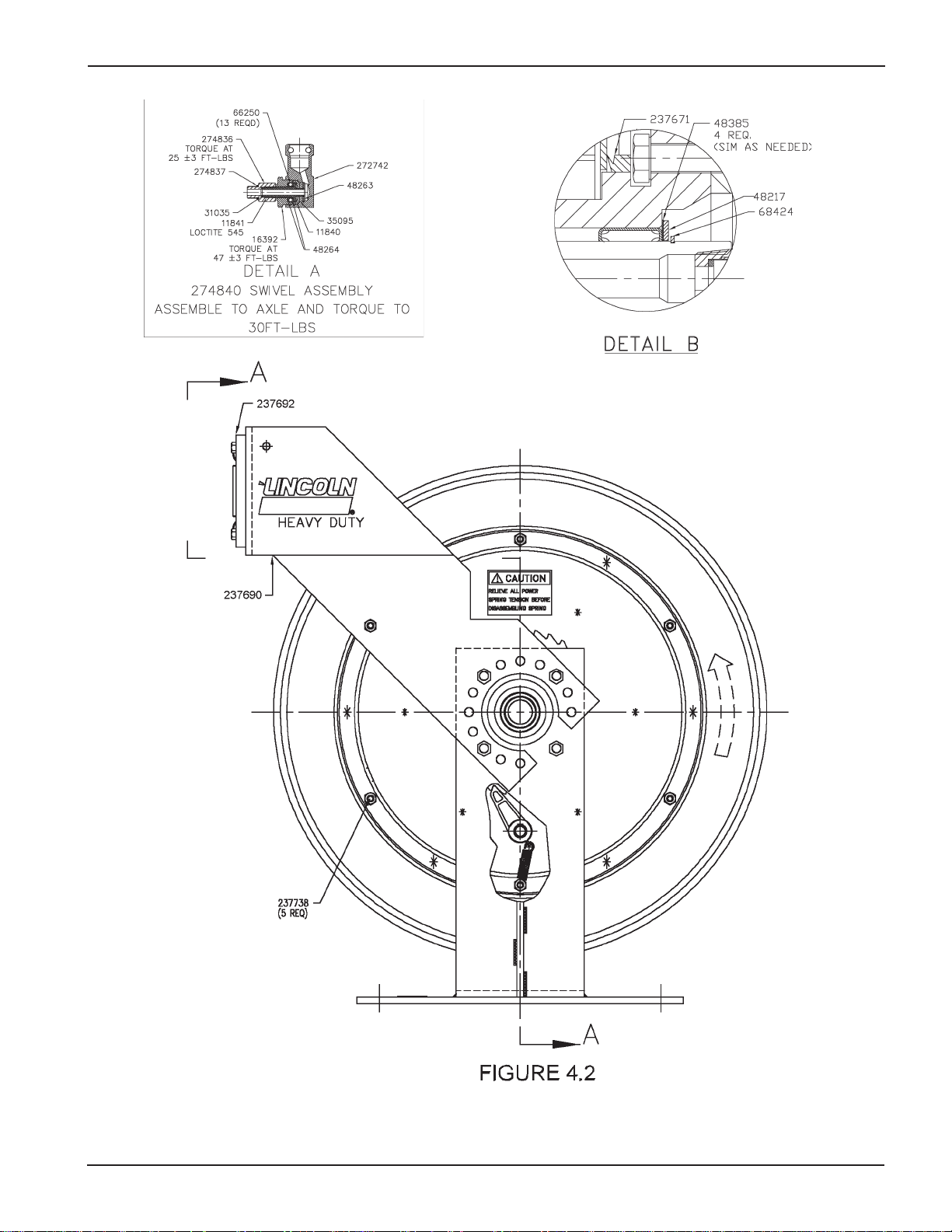
11840 1 Packing retainer 51022 7 Hex nut 237692 1 Roller outlet assembly
11841 1 Swivel stud 51304 5 Lock nut 237695 1 Extension spring
13162 1 Pin 51412 10 Hex nut 237738 6 Carriage bolt
15674 2 U-keeper 66250 13 Ball 237739 1 Carriage bolt
16392 1 Swivel nut 66316 1 Tru-arc 247136 1 Hose clamp
31035 1 Gasket 68424 1 Tru-arc 272167 1 Hose Clamp
35095 1 Swivel packing 237656 1 Support asembly 272168 1 Hose Clamp
48217 1 Washer 237670 1 Arbor and ratchet casting 272742 1 Swivel body
48263 1 Packing washer 237671 1 V-ring seal 273065 1 Adapter assembly
48264 2 Thrust washer 237672 1 Power spring assembly 273212 1 Outlet adapter
48327 1 Washer 237673 1 V-ring seal 274835 1 Axle
48385 4 Shim washer 237680 1 Sheave assembly 274836 1 Swivel adapter©
50014 4 Hex head screw 237683 1 Latch pawl 274837 1 O-Ring
50033 4 Screw 237690 1 Roller outlet arm assembly 274840 1 Swivel assembly©
© Indicates change

Page Number - 9
Form 402140
One Lincoln Way
St. Louis, MO 63120-1578
USA
Phone +1.314.679.4200
Fax +1.800.424.5359
© Copyright 2006
Printed in USA
Web site:
www.lincolnindustrial.com
This product is designed to meet the requirements of the
relevant EC directives. To maintain this status all installation,
repair and maintenance work must be carried out by qualified
personnel using only original spare parts. Contact you nearest
Lincoln dealer or you may call Lincoln Technical Service.
Declaration of Conformity
We, Lincoln Industrial Corporation, declare under our sole re-
sponsibility that the product Hose Reel Model 82206 to which
this declaration relates, is in conformity with the following
standards or other normative documents: EN 292-1:1991, EN
292-2:1991, following the provisions of Directive 89/392/EEC.
Paul Conley, Chief Engineer
Lincoln Industrial
Ce produit est conçu pour répondre aux normes des directives
européennes. Pour maintenir celles-ci, l’installation, la répara-
tion et la maintenance ne doivent être effectuées que par un
personnel qualifié en n’utilisant que des pièces d’origine. Pour
toute assistance technique et la fourniture de pièces déta-
chées, veuillez vous adresser à votre revendeur le plus proche
ou Lincoln service technique.
Déclaration de Conformité
Nous, Lincoln Industrial Corporation, déclarons sous notre
seule responsabilité que le produit Enrouleur de Tuyau,
Modèle 82206 auquel se réfère cette déclaration est conforme
aux normes ou autres document normatifs EN 292-1:1991,
EN 292-2:1991 conformément aux dispositions de Directive:
89/392/EEC.
Dieses Produkt wurde unter Berücksichtigung der in den EG-
Richtlinien festgelegten Anforderungen entwickelt. Um diesen
Qualitätsanforderungen zu entsprechen,dürfen Installationen,
Reparatur- und Wartungsarbeiten nur von Fachleuten unter
Anwendung von Original-Ersatzteilen ausgeführt werden.
Wenden Sie sich bei technischen Fragen oder beim Bedarf
von Ersatzteilen an den nächstgelegenen autorisierten Fach-
händler oder an Lincoln Technischer Service.
Konformitätserklärung
Wir, Lincoln Industrial Corporation, erklären in alleiniger
Verantwortung, dass das Produkt Schlauchaufroller Modell
82206 auf das sich diese Erklärung bezieht, mit den folgenden
Normen oder normativen Dokumenten übereinstimmt: EN
292-1:1991, EN 292-2:1991 gemäß den Bestimmungen der
Richtlinie 89/392/EEC.
Este producto está diseñado y construido para satisfacer los
requerimientos de las directivas de la Comunidad Europea.
Para mantener este estado, es necesario
que la instalación, reparación y mantenimiento sólo sean efec-
tuados por personal cualificado y utilizando recambios origina-
les. Para asesoría técnica o adquisición de recambios, tengan
la amabilidad de ponerse en contacto con el concesionario
más cercano o Lincoln Servicio Técnico.
Declaración de Conformidad
Lincoln Industrial Corporatión declara bajo su exclusiva
responsabilidad la conformidad del producto Carreta porta-
manguera Modeló 82206, al que se refiere esta declaración,
con las normas o otros documentos normativos: EN 292-
1:1991, EN292-2:1991 de acuerdo con las disposiciones de
Directiva 89/392/EEC.
English
French
German
Spanish
Table of contents
Other Lincoln Cables And Connectors manuals
Popular Cables And Connectors manuals by other brands

HDCVT TECHNOLOGY
HDCVT TECHNOLOGY HDV-914 user manual

Amphenol
Amphenol PowerLok PL182X-301-50 manual

Renesas
Renesas Extension Cable for FLX160 M3T-F160-EXTC user manual

SET
SET Lynx-CustomFit LYNX2-MPO installation manual

Staubli
Staubli SLS425-BFT/N Assembly instructions

IMS
IMS MD-CC100-000 Specification sheet