Vivo V656IPW User manual

1/16
User Guide
V656IPW
VoIP-DECT Telephone
General
-DECT / DECT 6.0
-SITEL Dialog RHEA platform SC14452
-Standard configuration of 1 VoIP account. Maximum of 4 VoIP accounts
-IPv4 / IPv6
-10 Non-volatile Hot Keys
-WAN port and LAN port
-Headset connectivity (check with your distributor for this option before order)
-PoE (check with your distributor for this option before order)
Server Compliance
-Asterisk / Broadsoft / Alcatel / NEC / Avaya basic call features supported
Codecs and Voice Features
-Wideband codec: G.722
-Narrowband codec: G.711μ/A, ILBC
-G.729
-VAD, CNG, AEC, PLC, AJB, AGC
-Full-duplex speakerphone with AEC

2/16
A. Handset Key Mapping and Description
Diagram above shows the keypad mapping on the wireless handset of V656IPW.

3/16
B. Base Unit Key Mapping and Description
Diagram above shows the keypad mapping of the base-station of V656IPW.
Key
Function Description
PAGE
To page / to locate the wireless handset
R
Call-Flash
VOL –
To decrease loudspeaker volume on the base-station
VOL +
To increase Loudspeaker volume on the base-station
HOLD
To put a call on hold
REDIAL
Last Number Redial
SPK
Speakerphone ON / OFF. Toggle
H0 –M3
Hidden Keys for Technician
M0 –M9
Pre-programmable Memory Keys

4/16
C. Installation
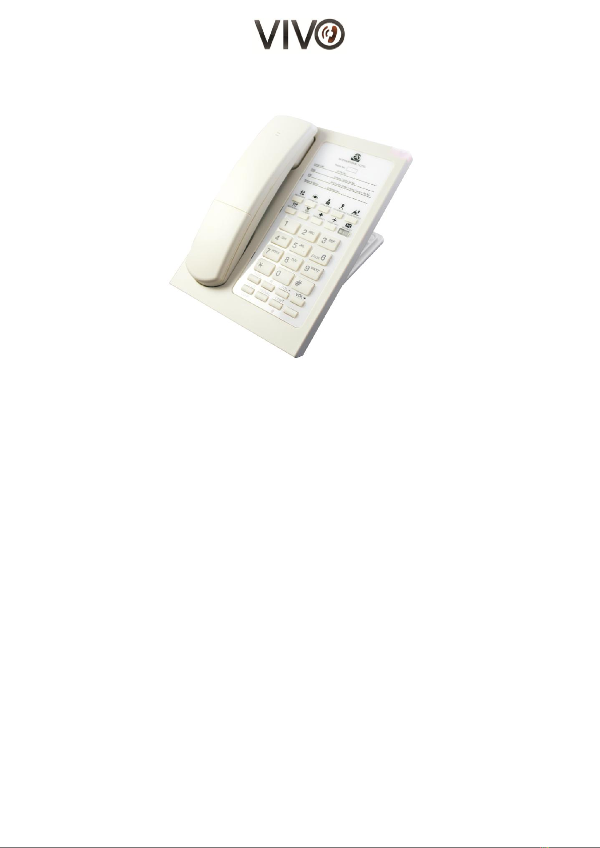
1. Unpack the box and check for the following items enclosed:
a. Main unit and laminated faceplate
b. DECT Handset
c. RJ45 Ethernet cable
d. D.C. Power Adapter (check with your vendor for this item may not be included)
2. Connect one end of the Ethernet cable to the WAN port of the main unit, and the other end
to the wall Ethernet outlet
The WAN port is under the logo
3. For your computer, connect its Ethernet cable to the LAN port of the main unit
The LAN port is under the logo
D. Call Operation
(I) Initiate a Call
Using the cordless handset
1. Lift the handset from the cradle
2. Press the “Off-hook”button to get a line
3. Listen to the dial tone
4. Press the desired number or press a memory button for auto dial
5. During a call, press the “Off-hook” button to activate the hands-free function i.e.
speakerphone mode
6. To drop the call temporarily and make another call, press the flash button
7. To end the call, place the handset back on the cradle or press the “On-hook” button
Using the base unit speakerphone
1. Press speaker button, SPK. The red LED indicates that the speaker is active
2. Listen to the dial tone
3. Press the desired number or press a memory button for autodial
4. To drop the call temporarily and make another call, press the flash button
5. To end the call, press the speakerphone button again. The LED will go off
(II) Answer a Call
An audible ringing sound and the flashing LED indicates and incoming call. You may do one of the
following to answer the incoming call:
Using the wireless handset
1. Lift the cordless handset (if it’s on the cradle) to answer the call. Press the “Off-hook” button
(if it’s not on the cradle) to answer the call
2. To end the call, either place the cordless handset back on the cradle/ or press the “On--hook”
button

5/16
Using the base unit speakerphone
1. Press the speakerphone button to answer the call.
2. To end the call, simply press the speakerphone button again. The line status LED will turn off.
(III) Redial
Using the wireless handset
1. Lift the handset and press the “Off-hook” button to get a line.
2. Press the “REDIAL” button to dial out the last dialed number from the memory.
3. To end the call, place the handset back on the cradle or press the “On-hook” button
Using the base unit speakerphone
1. Press the speakerphone button. The red LED indicates that the speakerphone is active, press the
REDIAL button to dial out the last dialed number from the memory.
2. To end the call, press the speakerphone key again. The LED will turn off.
(IV) Direct Memory Dialling
Using the wireless handset
1. Lift the handset. Press the M1 button to dial the pre-stored number from the direct memory.
2. To end the call, place the handset back on the cradle, or press the “On-hook” button
Using the base unit speakerphone
1. Press the desired memory button (one of the ten memories on the base unit). The red LED
indicates that the speakerphone goes active automatically. It dials out the pre-stored number from
the direct memory automatically.
2. To end the call, press the speakerphone key again. The LED will turn off.
(V) Call Flash
Press the FLASH button, labelled on the base unit, to switch between calls. This will put the
current call on-hold and allow to you make a call or listen to another call.
(VI) Call Hold
During conversation, press the HOLD button to place a call on hold. The other party will hear hold
music.
To deactivate the call on hold, press the HOLD button again.

6/16
E. Volume Adjustment
(I) Ringer Volume
When V656IPW is in standby mode, press Vol+ or Vol- on the base-unit to increase or decrease the
ringing volume of the base-station respectively.
(II) Call Volume
During a hand-free call, press Vol+ or Vol- on the base-unit to increase or decrease the call volume
of the speakerphone on the base-station, respectively.
During a call on the wireless handset, press Vol+ or Vol- on the base-station to increase or decrease
the call volume of the wireless handset.
F. Message Retrieval
The Message Retrieval button named, “MSG”, can be found on both the handset and the base unit. It is
reserved as a dedicated direct memory button that allows you to retrieve a message from the mail box
by means of a single key press action. In the event of a new incoming message, the “MSG” button
lights up to alert users.
Simply press the “MSG” button on the base unit or the handset. The base unit goes off-hook and dial to
retrieve the message from the mail box automatically.
Please see section for memory programming guide.
G. WebPortal | Phone Setting Guide
The Web Portal of V656IPW can be accessed by Google Chrome, Internet Explorer and Mozilla Firefox.
(I) To Log In
You must find find out the IP Address of V656IPW in order to log on to its WebPortal for
configuration and settings.
a. To retrieve the IP Address of V656IPW
Take out the laminated faceplate carefully. You will see four hidden function keys
undernearth.
Press once the leftmost button. The IP Address is announced on the loudspeaker.
Enter http://< IP Address of V656IPW> on a web browser.
There are two levels of access: (1) "Adminstrator / Full access" and (2) "Users / Limited
access" (see below).

7/16
The welcome page shows the hardware version and firmware date code of the model (see
below).
Figure 1 - Welcome page of the Web Portal
b. User Access
When prompt for login, enter "users" for user name, "1111" for password.
Users have limited functions and controls over the behavor of the phones.
Firmware upgrade, SIP registry settings are not available to users.
c. Administrator Access
When prompt for login, enter "admin" for user name, "admin" for password. Adminstrators
enjoy full access to all configurations and actions important to phone settings. Firmware
upgrade, SIP registry settings are only available to administrators.
(II) To Logout
When done, remember to logout completely.
Clear the cache / cookie of your web browser so that the previous login is not re-cycled by
the next user.
(III) To set login password for Web Portal
There is no default password for first-time login. It is recommended for administrators to
set login name and password to enhance security.

8/16
1. Go to the Admin page.
2. On the left panel, find the "Set Password" link and press on it.
3. Enter username for login name
4. Enter password and re-enter for confirmation purpose
5. When the mask password box is checked, both password entries are masked. To
un-mask, simply un-checked the mask password box.
Figure 2 - Set Password for the Web Portal

9/16
(IV) Network Settings
Administrators may choose to operate in either dynamic IP environment or static IP environment.
1. Go to the Network page.
2. Change network setting parameters.
3. After making changes, click save at the bottom of the page
4. A pop-up window appears, you may choose between "back" and "restart"
5. In order to have the changes take effect immediately, click "restart"
6. You can always preserve the changes and decide to restart the phone at a later time
Figure 3 - Network Settings page on Web Portal
(V) SIP Account Settings
Parameters for Session-initiation-protocol (SIP) such as registrar address, proxy address, port etc.
can be found in the "SIP Accounts" section on the Configuration page.
1. Go to Configuration page
2. On the left panel, click Register
3. A dropdown menu appears. Click on the "Account 1" link
4. Enter the SIP registration particulars for Account 1.
5. When done, click Save
6. The changes take effect immeidately
7. Complete the entries for Account 2 and Account 3

10/16
Figure 4 - Account Settings page on Web Portal
Parameters for Call settings for each account can be found under the title, "Call Settings", on the
left panel.
Such parameters include:
- Call Forward Mode
- Call Waiting activation / deactivation
- DND activation / deactivation
- Auto-Answer activation / deactivation
Parameters for network environment such as Network-Address-Traversal (NAT) can be found under
“SIP/NAT Settings”.
Parameters for Audio settings for each account can be found under the title, "Audio Settings", on
the left panel.
Such parameters include:
- DTMF mode (in-band / RFC2833 / SIP INFO)
- Audio Codec preference (PCMU / PCMA / G.722 / G.729 / iLBC)
- ToS
- Jitter
When done with changes, click Save.
The changes take effect immediately.

11/16
(VI) Direct memory –to store “M1” and “MSG”
The 10 memory keys can be pre-programmed in the Configuration page.
Memory Key 9 is reserved for “MSG”. See Section B – Base Unit Key Mapping.
Figure 5 - Memory key and MSG button settings page on Web Portal

12/16
H. DECT Handset Registration
1. Enable the base unit registration mode
There are 2 ways to do it:
Option 1:
(a) Press and hold the page key for 6 sec on the base unit
(b) LED starts blinking indicating that the base unit has entered registration mode
Option 2:
(a) Base unit is in standby mode
(b) Enter the code HOLD “# # * * “ HOLD
(c) A long “beep” tone indicates that the base unit has entered registration mode and the page LED
starts blinking.
2. Activate the handset registration mode
While the base unit is in registration mode (LED blinking), take the following steps:
i. The handset is in standby mode
ii. Press the “HOLD” button
iii. A short “beep” tone can be heard
iv. Enter the code “ # # * * ” and then press the “HOLD” button again
v. A long “Beep” tone indicates that the handset has entered the registration mode and it’s
searching for the base unit.
vi. An audible tone can be heard upon successfully registration
vii. Press the “On” button to get a line and hear the dial tone
I. DECT Handset De-registration
Each base unit is capable of registering a maximum of 4 handsets. When the base registration entry is
full, no additional handset can be registered to that base unit. In this case, it is necessary to erase the
base entry by following the procedure below:
To clear all handset registration at the Base-station
Option 1:
(a) Base-station is in standby mode
(b) Enter the code HOLD “# # # 7” HOLD
(c) A long “beep” tone indicates that the base unit has de-registered all handsets
Option 2:
(a) Disconnect the power from the base unit
(b) Press and hold the “Page button” on the base unit and re-connect the power

13/16
(c) Keep holding down the page button for approx. 10 sec until a “Beep” tone is heard, which
indicates that all previously registered handsets are erased from that base unit and the base
registration entry is now empty
To selectively de-register a handset at the base-station
1. Handset unit is in standby mode
2. Enter the code HOLD “# # # 7”HOLD on the handset
3. A long “beep” tone indicates that the handset has de-registered itself at the base-station
J. DECT Handset Setup Menu
We provide an interface for technicians to enter parameters on the handset such as clock display info,
ringer tone, and to active DECT registration and de-registration. Details below.
(I) To acceess the setup menu on the DECT handset
1. Enter the code, “# 0 8 8 HOLD” in idle state / standby mode.
2. Hear a short “beep” tone
3. See that you are in the first level of the setup menu
(II) To navigate the setup menu on the DECT handset
Use the “VOL+“ and “VOL-” buttons for going up and down the menu, respectively.
Press “HOLD” key for confirmation of selection or changes made.
Press “On-hook” key, to exit the menu.
(III) Content of the setup menu on the Handset
First Level
Second Level
Third Level
Definition / Description of Setting
Date & Time
Date and Time settings
Time Format
12hr / 24hr display format setting
C. Log Timer
Set the time lapse for the call log to be
automatically erased –10 mins / 30 mins / 24
hours / off
Show Clock
Enable/ disable the real time clock display during
standby mode
HS setup
Contrast
Adjust the 6 levels of LCD contrast
Handset Tone
Ring Volume
Customize 3 levels ringing volume
Ring Melody
Choose any of the 16 ringing melody
Key Tone
Choose to play tone or melody or no tone at all

14/16
Low Batt
Turn on / off the alert tone in case of low battery
Auto Answer
Turn on / off the answer automatically feature.
“Auto Answer” refers to the action taken by the handset to
enter the dialing state as soon as it leaves the charging cradle.
Handset Name
Set the name to be displayed on the idle screen
Language
Default display language is English
Register
Enable the DECT registration mode
Default
Restore to factory default settings

15/16
IMPORTANT SAFETY INSTRUCTIONS
WHEN USING YOUR TELEPHONE EQUIPMENT, BASIC SAFETY PRECAUTIONS SHOULD ALWAYS BE FOLLOWED
TO REDUCE THE RISK OF FIRE, ELECTRIC SHOCK AND INJURY TO PERSONS. INCLUDING THE FOLLOWING:
1. READ AND UNDERSTAND ALL INSTRUCTIONS IN THIS MANUAL.
2. FOLLOW ALLWARNINGSAND INSTRUCTIONS MARKED ON THE PRODUCT.
3. UNPLUG THE PRODUCT FROM THE WALL OUTLET BEFORE CLEANING. DO NOT USE LIQUID CLEANER OR
AEROSOL CLEANERS. USE A DAMP CLOTH FOR CLEANING.
4. DO NOT USE THIS PRODUCT NEAR WATER FOR EXAMPLE NEAR A BATHTUB, WASH BOWL, KITCHEN SINK
OR LAUNDRY TUB, IN AWET BASEMENT, OR NEAR A SWIMMING POOL.
5. DO NOT PLACE THIS PRODUCT ON AN UNSTABLE CART, STAND OR TABLE. THE PRODUCT MAY FALL,
CAUSING SERIOUS DAMAGE TO THE PRODUCT.
6. SLOTS AND OPENINGS IN THE CABINET AND THE BACK OF BOTTOM ARE PROVIDED FOR VENTILATION,
TO PROTECT IT FROM OVERHEATING, THESE OPENINGS MUST NOT BE BLOCKED OR COVERED. THE
OPENINGS SHOULD NEVER BE BLOCKED BY PLACING THE PRODUCT ON THE BED, SOFA, RUG OR ANY
OTHER SIMILAR SURFACE. THIS PRODUCT SHOULD NEVER BE PLACED NEAR OR OVER A RADIATOR OR
HEAT REGISTER. THIS PRODUCT SHOULD NOT BE PLACED IN A BUILT-IN INSTALLATION UNLESS PROPER
VENTILATION IS PROVIDED.
7. NEVER PUSH OBJECTS OF ANY KIND INTO THIS PRODUCT THROUGH CABINET SLOTS AS THEY MAY
TOUCH DANGEROUS VOLTAGE POINTS OR SHORT OUT PARTS THAT COULD RESULT IN A RISK OF FIRE
OR ELECTRIC SHOCK. NEVER SPILL LIQUID OF ANY KIND ON THE PRODUCT.
8. TO REDUCE THE RISK OF ELECTRIC SHOCK DO NOT DISASSEMBLE THIS PRODUCT, BUT TAKE IT TO A
QUALIFIED SERVICEMEN WHEN SOME SERVICE OR REPAIR WORK IS REQUIRED. OPENING OR
REMOVING COVERS MAY EXPOSE YOU TO DANGEROUS VOLTAGES OR OTHER RISKS. INCORRECT
REASSEMBLE CAN CAUSE ELECTRIC SHOCK WHEN THEAPPLIANCE IS SUBSEQUENTLY USED.
9. UNPLUG THIS PRODUCT FROM THE WALL OUTLET AND REFER SERVICING TO QUALIFIED SERVICE
PERSONNEL UNDER THE FOLLOWINGCONDITIONS:
- WHEN THE POWER SUPPLY CORD OR PLUG IS DAMAGED OR FRAYED
- LIQUID HAS BEEN SPILLED INTO THE PRODUCT.
- IF THE PRODUCT HAS BEEN EXPOSED TO RAIN OR WATER.
10. IF THE PRODUCT DOES NOT OPERATE NORMALLY BY FOLLOWING THE OPERATING INSTRUCTIONS.
ADJUST ONLY THOSE CONTROLS THAT ARE COVERED BY THE OPERATING INSTRUCTIONS BECAUSE
IMPROPER ADJUSTMENT OF OTHER CONTROLS MAY RESULT IN DAMAGE AND WILL OFTEN REQUIRE
EXTENSIVE WORK BYA QUALIFIED TECHNICIAN TO RESTORE THE PRODUCT TO NORMAL OPERATION.
- IF THE PRODUCT HAS BEEN DROPPED OR THE CABINET HAS BEEN DAMAGED.
- THE PRODUCT EXHIBITA DISTINCT CHANGE IN PERFORMANCE.
11. AVOID USING A TELEPHONE (OTHER THAN A CORDLESS TYPE) DURING AN ELECTRICAL STORM. THERE
MAY BE AREMOTE RISK OF ELECTRIC SHOCK FROM LIGHTING.
12. DO NOT USE THE TELEPHONE TO REPORT A GAS LEAK IN THE VICINITY OF THE LEAK.SAVE THESE
INSTRUCTIONS
WARRANTY EXCLUSIONS
This warranty does not cover, or may be voided by the followings:
1. Any damage resulting from abuse or misuse (i.e. liquid spills, abuse, or customer’s modification (
warranty label broken) of the telephone.
2. Any damage caused by failure to follow operating or installation instructions provided with the
telephone.
3. New faceplates or damage to the faceplate or discoloration of the telephone.
4. Any damage resulting from improper connection of the telephone to other equipment.
5. A telephone used in a harsh or corrosive environment.
6. Incompatibility with anything other than the PBX for which the telephone was intended during
purchased.
7. Cords, connectors and replaceable batteries.
8. Force majeure.
9. Damages in transit.
10. Any damage resulting from unauthorized modification or repair of the telephone.

16/16
HTI PRODUCT SUPPORT
Should you need any technical assistance for this product, please contact Hotel Technology
International Limited:
Telephone : +44 (0) 203 405 1200
Email : : support@hotel-tech.com
Table of contents