Vixen VMC260L User manual

VMC260L
Optical Tube Unit
Instruction Manual for

PREFACE
Specifications
Contents
This instruction manual will assist you in the safe use of the product. Please be sure to read the safety precautions described below
before using the product. Keep this manual nearby to find quick answers to questions.
Thank you very much for your purchase of a Vixen VC260L optical tube unit.
Please read throughout the instruction manual before use and follow the instructions properly.
WARNING !
Never look directly at the sun with the telescope or its finder scope or eyepiece.
Permanent and irreversible eye damage may result.
Be sure to turn the focus knob clockwise to the end of its rotation to protect the primary mirror against vibration during
transportation. (Do not tighten too strong.) This is important to prevent the optical axis from being out of collimation.
CAUTION
Do not leave the optical tube uncapped in the daytime. Sunlight
passing through the telescope or finder scope may cause a fire.
Do not use the product while moving or walking, injuries could result
from a collision with objects or from stumbling or falling.
Keep small caps, plastic bags, or plastic packing materials away from
children. These may cause a danger of swallowing or suffocation.
Do not use the product in a wet environment. This could damage the
product, and it may result in electrical shock or a fire.
Do not attempt to disassemble or alter any part of the product that is
not expressly described in this manual.
Be sure to handle the product carefully when setting up. Not to drop a
screw, a tool, or an object inside the optical tube. This could damage
the product or lead to injury
Do not leave the product inside a car in bright sunshine, or in other hot
places. Keep away strong heat source away from the product.
When cleaning, do not use solvents such as paint thinner or similar
products.
Do not expose the product to rain, water, dirt or sand.
Avoid touching any lens surfaces directly with your hands. In case a
lens becomes dirty with fingerprints or general smears, gently wipe it
using a commercially available lens cleaner and lens cleaning paper or
cloth or consult your local Vixen dealer.
Blow off dust on lenses using a commercially available blower brush.
For storage, keep the product in a dry place and do not expose to
direct sunlight.
HANDLING AND STORAGE
About Transportation
Model
Optical design
Effective aperture
Focal length
Focal ratio
Light gathering power
Resolving power
Limiting magnitude
Adapter threads
Push-fit
Optical tube length
Optical tube diameter
Weight
7x50mm Finderscope with illuminated reticle (7 degrees field of view) / Wide dovetail slide bar (built-in)
Metal carry handle (built-in) / Flip mirror diagonal / Saddle plate
VMC260L
Precision spherical mirror and Meniscus lens system
260mm
3000mm
1:11. 5
1380x unaided eye
0.45 arc seconds
13.8
60mm, 42mm for T-ring
50.8mm, 31.7mm (using a Flip mirror diagonal)
680mm (720mm incl. focus knob)
304mm
10 kg (12 kg incl. accessories)
1
1
1
1
1
2
1
VMC260L Optical Tube Assembly
Saddle Plate (This may not be included in your specific model.)
7X50 Finderscope with Illuminated reticle
Flip Mirror Diagonal
Allen wrenches, 6mm and 2mm on a side
M8 bolts
Instruction Manual (This booklet)
This manual applies to VMC260L for AXD Mount by way of example. You may occasionally find descriptions in the text not relevant to your
model. Be sure to read instructions for the AXD Mount with this manual if you purchase the VMC260L telescope as a complete package.
Objective Mirror
Visual Back
Dimensions and Weight
Accessories
The VMC260L for AXD shipping box contains the items listed below. Check if all the items are included.
Note: The contents of your VMC260L optical tube unit may differ when you
purchase this item as a mount package complete with an optical tube
2

Carry handle Finderscope bracket
7x50mm Finderscope
with illuminated reticle
Eyepiece
(Sold separately)
Flip mirror diagonal
Lock knobs
Secondary mirror cell
Wide dovetail slide bar Saddle plate
Place the saddle plate on the mount head so that the screw holes
match each other.
Attach the saddle plate
securely with the two M8
bolts supplied with the
VMC260L.
Loosen the lock knobs on
the saddle plate before you
attach the optical tube.
Slide the dovetail slide bar on
the bottom of the optical tube
onto the sunken platform of
the saddle plate.
With holding the optical tube,
tighten the two lock knobs on
the saddle plate securely.
Attaching the Saddle Plate to a mount head Attaching the VMC260L optical tube unit to the Saddle Plate
The AXD Mount is shown by way of example.
Be sure to handle the saddle plate and VMC260L optical tube unit carefully as those are rather heavy items.
1
1
2
2
3
Allen wrench
M8 bolt
M8 bolt
Saddle plate
Name of Each Part on the VMC260L
Attaching the VMC260L to a Mount
Allen wrench
Lock knobs
Lock knobs
Lock knobs
Lock knobs
Saddle plate
Saddle plate
Optical tube
Optical tube
Dovetail slide bar
Dovetail slide bar
M8 bolt
M8 bolt
Saddle plate
3

Loosen three grub screws in advance on the finder bracket with the
supplied Allen wrench until the tips of these screws no longer extend
into the inner part of the bracket ring. Also loosen three adjustment
screws on the front side of the bracket ring equally by hand to allow
passage of the finderscope.
Slide the finderscope into the bracket ring from its objective end as
shown in the figures. Tighten the three grub screws gently and equally
with the Allen wrench at this stage so that the finderscope become
stable and does not rattle inside the bracket ring. Then, tighten the
three adjustment screws equally to fix the finderscope.
It is unavoidable that the grab screws mar the surface of the
finderscope tube by tightening.
Loosen the chrome lock screw on the finder bracket shoe of the
telescope optical tube. Slide the finderscope onto the finder bracket
shoe and tighten the chrome lock screw securely.
Setting up the 7x50mm Finderscope
(Attaching to the Finder Bracket)
Attaching the Flip Mirror Diagonal
Loosen the two setscrews on
the visual back and insert the
flip mirror diagonal as shown in
the figure.
Tighten the two setscrews to
hold the flip mirror diagonal
steadily after inserting it into the
visual back.
Attaching an Eyepiece
Balancing the VMC260L using a Counterweight(s)
Loosen the setscrew on the flip
mirror diagonal and insert a
31.7mm eyepiece (1.25” barrel)
into its eyepiece adapter as
shown in the figure.
Tighten the setscrew to hold the
eyepiece steadily after inserting
it into the eyepiece adapter.
Set the eyepiece to use either
in the 90-degree angled or
straight through viewing
position.
You need to align the finderscope before use. Read page 6 to
adjust the finderscope after you finish assembling the finderscope.
Finder bracket
7x50mm Finderscope
Finder bracket
Grub screw
Adjustment
screw
Adjustment
screw
1
1
2
1
2
3
2
Flip mirror
diagonal
Visual back
Setscrews on the
visual back
Flip mirror
diagonal
Setscrews on the
visual back
Be sure to balance the telescope on the AXD mount (or your
equatorial mount) correctly to ensure smooth and accurate
movements of the RA and DEC axes. An unbalanced mounting may
cause vibration and can result in tracking errors or failure of the
rotation mechanism.
Finder bracket
7x50mm Finderscope
Finder bracket
Grub screw
Adjustment
screw
Adjustment
screw
Adjustment
screws
(3 positions)
Grub screws
(3 positions)
Allen wrench
Adjustment
screws
(3 positions)
Grub screws
(3 positions)
Chrome lock
screw
lide the finderscope onto the bracket
shoe from the rear end.
Chrome lock
screw
Allen wrench
Chrome lock
screw
lide the finderscope onto the bracket
shoe from the rear end.
Chrome lock
screw
Flip mirror
diagonal
Visual back
Setscrews on the
visual back
Flip mirror
diagonal
Flip mirror
diagonal
Flip mirror
diagonal
Flip mirror
diagonal
Flip mirror
diagonal
Eyepiece
Setscrew
Setscrews on the
visual back
Eyepiece
Eyepiece
Eyepiece
Setscrew
Setscrew
Setscrew
4

T-C Ring
(Optional)
Digital Camera Quick Bracket II
(Optional)
LCD / TV MonitorCCD Imaging Camera
(with C-mount)
Magnification of the telescope
Focusing the telescope
Visual Observing Configuration
Some of the optional accessories shown in this diagram will be needed if you take pictures with a DSLR camera, a compact camera, or a CCD/CMOS camera.
Photographic Configuration
Eyepiece
SLV20mm
SLV5mm
Telescope’s focal length
3000mm
3000mm
Magnification
150X
333X
EEyepiece’s focal length
20mm
9mm
Focus Knob
Prime Focus Photography
Afocal Imaging
(Collimation Photography)
Eyepiece Projection Photography
Eyepiece adapter
42mm to 31.7mm
(Part of the Flip
mirror diagonal) Eyepiece projection camera adapter (Optional)
Insert an eyepiece into the Eyepiece projection camera adapter
(between the two halves.)
Visual / Photographic Structures
The VMC260L requires an eyepiece to view images. The eyepiece
determines magnification of your telescope.
The telescope may come with the eyepiece as standard accessory
when you purchase it as a package including a mount.
Begin with an eyepiece with long focal length (large number in
millimeters). When using an eyepiece with short focal length, the
image becomes dimmer and the range of field of view becomes
narrower. Also, the range of sharp focus becomes smaller.
Dividing the focal length of the telescope by the focal length of the
eyepiece gives the magnification.
Example: Using the VMC260L with an SLV20mm or an SLV5mm eyepiece.
Look though the VMC260L with an eyepiece of low magnification.
Turn the focus knob clockwise or counter-clockwise until images in
the eyepiece’s field of view come to focus clearly.
Focus Knob
VMC260L
visual back
VMC260L
visual back
SX60 to 50.8 AD
(Supplied)
SX60 to 50.8 AD
(Supplied)
SX60 to 50.8 AD
(Supplied)
Extension Tube VC
(Optional)
Eyepiece 50.8mm
(Optional)
Eyepiece 31.7mm
(Optional)
Flip mirror diagonal
(Supplied)
Flip mirror diagonal
(Supplied)
Reducer for VMC
(Optional)
Commercially
available DSLR
camera (Body)
Compact
digital camera
T-ring
(Appropriate for your camera)
Wide photo adapter 60mm
(Optional)
Detaching the inner ring
of a T-ring to use it with
the Wide photo adapter 60.
Mirror flip knob
Eyepiece 31.7mm
(Optional)
5

Bring the target (tower) to the center of
the telescope’s field of view
Field of view of the finderscope
Center the target (tower)
Field of view of the finderscope
1
2
3
Dovetail slide bar
Choose a conspicuous target in the
distance (over 200m away) and place the
target in the center of a field of view of the
telescope.
The image in the telescope’s field of view
is usually upside down or mirror-revered
erect image.
Next, look through the finderscope. You
should probably find the same target
somewhere within the finder’s field of
view. In the illustration, the tower is seen
in the upper left of the finder’s field of
view.
If the crosshairs are out of focus, turn the
end of the finderscope’s eyepiece to reach
focus.
If the finderscope is out of focus on the target, please refer to focusing the finderscope on
page 7.
The image in the finderscope’s field of view is upside down. The crosshairs go to a tilted
position according to the state of the finderscope attached.
While looking through the finderscope, align the field of view with the telescope’s field of view
by loosening or tightening the adjustment screws on the finder bracket so that the target
comes close to the center of the field of view.
Adjust the finderscope by loosening two adjustment screws out of three adjustment screws
and tightening the remaining one adjustment screw so that the target can be shifted gradually
onto the center of the cross hairs. Be sure not to over loosen the adjustment screws to avoid
falling off.
Finally, you can see the target in the same position in the field of view of both the telescope
and finderscope. You should use an eyepiece of high magnification over 100x if you want to
increase the accuracy in centering a target in the telescope's field of view.
Be sure to align the finderscope with the telescope’s field of view before you start observing.
It is very difficult for the telescope user to locate a target object through the telescope’s field of view at high magnification, especially as the
field of view narrows. The use of a finderscope will make it much easier.
The field of view of finderscope does not align to the telescope when you merely attach it to the finder bracket shoe on the telescope.
The finderscope has crosshairs to aim the telescope at a target. This facilitates bringing the target to the center of the telescope's field of
view as you can overlay the target at the center of the crosshairs. A distant tower is used as a target in this manual by way of example.
About 7X50 finderscope with illuminated reticle
The necessity of a finderscope
Do not loosen adjustment screws too much. It may cause falling off the finderscope and may lead to injury or damage.
Caution!
7X50 Finderscope with illuminated reticle
Adjustment screws (3 points)
Bring the target (tower) to the center of
the telescope’s field of view
Center the target (tower)
7X50 Finderscope with illuminated reticle
Adjustment screws (3 points)
Tighten the screw A only first.
A : Screw
B : Nut
And then tighten the nut B by turning it to fix.
Field of view of
the finderscope
Image: Finderscope bracket and finderscope
B
B
A
6

The end of the eyepiece
(rubber armored)
Lock ring
Objective lens cell
(The front side of the finderscope)
Brightness adjustment dial
(combined with a power
switch)
Power “off” position
Brightness adjustment dial
(combined with a power
switch)
Power “off” position
The end of the eyepiece
(rubber armored)
Lock ring
Objective lens cell
(The front side of the finderscope)
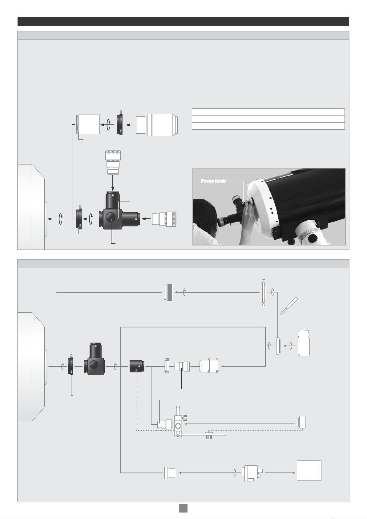
Tips on the collimation
Collimation screws
Secondary
mirror holder
Silhouette of
the secondary mirror
Silhouette of
the secondary mirror
Blade spider
Out of alignment
Misaligned slightly
Aligned correctly
Front side of the VMC260L
Your VMC260L is collimated at Vixen’s factory. The optical tube holds the collimation unless it is handled roughly. You can re-collimate the
VMC260L by way of the following procedures if necessary.
Use an eyepiece with high magnification and
repeat the above procedures so that you can
make more precise re-collimation of the
optical axis.
After you collimate the VMC260L properly,
you perform a star test with a medium to
high power eyepiece by selecting a star of
the second or third magnitude.
Note: Right after you focus on the star
precisely, defocus the star image slightly to
look at a diffraction pattern of the star.
It is essential to collimate the telescope
under good seeing condition.
If the concentric diffraction rings can be seen,
the optical axis has been re-collimated precisely.
Locate three Allen screws that
are set near the center of the
four-vane spider on the front of
the optical tube.
Attach an eyepiece with medium power (80x or adjacent) onto the
eyepiece holder and bring a bright star such as Polaris into the
field of view. Turn the
focus knob to defocus
the star image fully
until it is enlarged and
blurred as much as one
third of the viewing
field. The silhouette of
secondary mirror is seen
near the center of the blurred star image at this time.
If optical axis is aligned correctly, both the blurred star image and
silhouette of the secondary mirror can be seen at the center of the
field of view.
If it is not aligned concentrically, move those images to the center
of the field of view. With an Allen wrench, adjust the collimation
screw nearest or furthest from the direction of those images.
Turn the collimation screw clockwise or counterclockwise gradually
until the blurred star image and silhouette of the secondary mirror
are aligned concentrically in the center of the field of view.
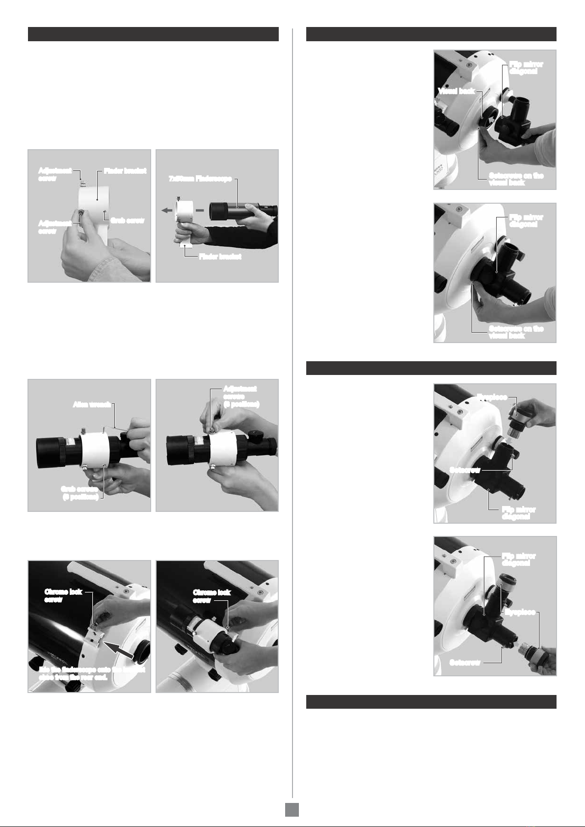
Adjusting the Illuminated Reticle on the Finderscope
The built-in illumination of the finderscope allows you to easily recognize the dim crosshairs in the dark field of view of the finderscope.
• The brightness of the illuminated reticle
varies gradually as you turn the brightness
adjustment dial.
• Don’t forget to turn off the illuminated reticle
after you finish using the finderscope.
• The dial will return to the “off “position if you
continue turning.
• Adjust the brightness properly. The brighter
the illumination of the reticle, the sooner the consumption of the battery. If too bright, it makes stars in the field of view invisible.
Focusing the Finderscope
The finderscope is adjusted to focus on infinity at Vixen’s factory before shipment. Because the ability of vision differs with individual persons,
it is possible that you will need to readjust the focus of your 7X50mm finderscope.
While looking through
the finderscope, turn the
end of the finderscope’s
eyepiece to left or right
by hand to bring the
cross hairs reticle into
focus.
How to Collimate the VMC260
15
6
7
2
3
4
1. It will be efficient if one person checks the star image and another
person adjust the collimation screws.
2. The star image moves largely even if you turn the collimation screw
a little.
3. If one of the collimation screws are hard to turn, be sure to turn the
opposite two screws in a reverse direction.
Focus on the crosshairs
While holding the lock ring
next to the objective lens
cell of the finderscope,
turn the objective lens
cell so that it loosens.
Find a position of the
objective lens cell that
brings a distant view
into focus. Tighten the
objective lens cell with
the lock ring at that
position.
Focus on the target
7

69ki-11-(Pro C5300S)(M)
5-17-3 Higashitokorozawa,Tokorozawa,Saitama359-0021, Japan
Phone +81-4-2944-4141(International)
F a x+81-4-2944-9722(International)
https://www.vixen.co.jp
Table of contents
Other Vixen Telescope manuals

Vixen
Vixen GREAT POLARIS User manual

Vixen
Vixen Porta A80Mf User manual

Vixen
Vixen ED 81S User manual

Vixen
Vixen Refractors A81M User manual

Vixen
Vixen R150S User manual

Vixen
Vixen Starbook-S Instruction Manual

Vixen
Vixen VC200L Manual

Vixen
Vixen SD Series User manual

Vixen
Vixen Porta A70Lf User manual

Vixen
Vixen VSD100F3.8 User manual

Vixen
Vixen Giant BT80M-A User manual

Vixen
Vixen BT81S-A User manual

Vixen
Vixen Skysensor 3S User manual

Vixen
Vixen VMC260L User manual

Vixen
Vixen VMC260L User manual

Vixen
Vixen GREAT POLARIS User manual

Vixen
Vixen BT-ED70S-A User manual

Vixen
Vixen BT126SS-A User manual

Vixen
Vixen Porta ED80Sf User manual

Vixen
Vixen BT81S-A User manual