VL Audio VIVA-715D User manual

OWNER MANUAL
PROFESSIONAL ACTIVE !
SPEAKER SYSTEMS
VIVA-715D

Before connecting and using the amplifier, please read this instruction manual carefully and keep it on hand for future reference. The manual is
to be considered an integral part of the product and must accompany the amplifier when it changes ownership as a reference for correct
installation and use as well as for the safety precautions. VL Audio will not assume any responsibility for the incorrect installation and/or use of
the product. !
WARNING: To prevent the risk of fire or electric shock, never expose this equipment to rain or humidity. !
1. All the precautions, in particular the safety ones, must be read with special attention, as they provide important information.!
2. The power supply voltage of this equipment is sufficiently high to involve a risk of electrocution; therefore, never install or connect the
product with the power supply switched on.!
Before powering up the amplifier, make sure that all the connections have been made correctly and that the voltage of your power mains
corresponds to the voltage shown on the rating plate on the unit; if it does not, please contact your VL Audio dealer.!
The metallic parts of the unit are earthed by means of the power cable. This is a Class I device and for its use it must be connected to a
grounded power source. To protect the power cable from damage, make sure that it is positioned so that it cannot be stepped on or crushed by
objects. To prevent the risk of electric shock, never open the amplifier. There are no parts on the inside that the user needs to access. Appliance
coupler or PowerCon Connector® is used to disconnect device from MAIN power. This device shall remain readily accessible after the
installation.!
3. Make sure that no objects or liquids can get into this product, as this may cause a short circuit. This apparatus shall not be exposed to
dripping or splashing. No objects filled with liquid, such as vases, shall be placed on this apparatus. No naked sources (such as lighted candles)
should be placed on this apparatus.!
4. Never attempt to carry out any operations, modifications, or repairs that are not expressly described in this manual. Contact your authorized
service centre or qualified personnel should any of the following occur:!
- the amplifier does not function (or functions in an anomalous way);!
- the power supply cable has been damaged;!
- objects or liquids have got into the unit;!
- the amplifier has been subject to heavy impact.!
5. When the amplifier is not to be used for long periods of time, switch it off and disconnect the power cable.!
6. If the amplifier begins to emit any strange odours or smoke, switch it off immediately and disconnect the power supply cable.!
7. Do not connect this product to any equipment or accessories not specified.!
For suspended installation, only use the dedicated anchoring points and do not try to hang this product using HANDLES or elements that are
unsuitable or not specific for this purpose.!
Also check the suitability of the support surface to which the product is anchored (wall, ceiling, structure, etc.), and the components used for
attachment (screw anchors, screws, brackets not supplied by VL Audio etc.), which must guarantee the security of the system/installation over
time, also considering, for example, the mechanical vibrations normally generated by the transducer.!
To prevent the risk of falling equipment, do not stack multiple units unless this possibility is specified in the instruction manual.!
8. VL Audio strongly recommends this product is installed by professional qualified installers (or specialised firms) who can ensure correct
installation and certify it according to the regulations in force.!
THE ENTIRE AUDIO SYSTEM MUST COMPLY WITH THE CURRENT STANDARDS AND REGULATIONS REGARDING ELECTRICAL SYSTEMS.!
9. SUPPORTS AND TROLLEYS!
The equipment should only be used on trolleys or supports, where necessary, that are recommended by the manufacturer. The equipment/
support/trolley assembly must be moved with extreme caution. Sudden stops, excessive pushing force and uneven floors may cause the
assembly to overturn.!
10. There are numerous mechanical and electrical factors to be considered when installing a professional audio system (in addition to those
which are strictly acoustic, such as sound pressure, angles of coverage, frequency response, etc.).!
11. HEARING LOSS!
Exposure to high sound levels can cause permanent hearing loss. The acoustic pressure level that leads to hearing loss is different from person
to person and depends on the duration of exposure. To prevent potentially dangerous exposure to high levels of acoustic pressure, anyone who
is exposed to these levels should use adequate protection devices. When a transducer capable of producing high sound levels is being used, it
is therefore necessary to wear ear plugs or protective earphones. See the technical specifications in the instruction manual for the maximum
sound pressure the loudspeaker is capable of producing.
CAUTION: to prevent electric shock hazard, do not connect to mains power supply while grille is removed
SAFETY PRECAUTIONS

To prevent the occurrence of noise on the cables that carry microphone signals or line signals (for example, 0 dB), only use screened cables and
avoid running them in the vicinity of: !
- equipment that produces high-intensity electromagnetic fields (for example, high power transformers);!
- mains cables; !
- lines that supply loudspeakers.!
!
The equipments considered in this manual can be used in electromagnetic environment E1 to E3 as specified on EN 55103-1/2: 2009.
OPERATING PRECAUTIONS
- Do not obstruct the ventilation grilles of the unit. Situate this product far from any heat sources and always ensure adequate air circulation
around the ventilation grilles.!
- Do not overload this product for extended periods of time.!
- Never force the control elements (keys, knobs, etc.).
- Do not use solvents, alcohol, benzene or other volatile substances for cleaning the external parts of this product.
Back in 2017 VL Audio moved into the forefront of the loudspeaker technology with the introduction of the VEDA Series: a loudspeakers range that
was able to deliver perfect and powerful sound with a lightweight cabinet strong enough to withstand everyday use.!
The VL Audio R&D team kept evolving the VIVA technology during the last decade, developing reference products such as the VIVA-715D!
The VL Audio Team always has the performer’s needs at the forefront of the design in order to create new lines of speakers with renewed features,
improved sound clarity and definition and even lighter weight systems. !
The latest iconic design is the VIVA Series: an evolution in the active loudspeaker technology with a revolutionary design and sound. Every detail
of the 7 Series has been carefully studied in order to offer musicians and professionals the perfect tool to amplify their performance, night after
night. High quality materials, precise manufacturing, careful assembly and extensive quality control procedures complete the groundbreaking
design work of the VL Audio R&D team. !
COMPONENTS
All the transducers in the VIVA Series speakers feature high power magnets in order to guarantee a better performance and make for easier
transportation.!
All Compression drivers and Transducers are precision built taking advantage of VL Audio superior moulding, assembly technologies and a wealth
of professional knowledge and experience dedicated to achieving extremely high standards. !
AMPLIFIERS
VIVA 7 Series two-way speakers are equipped with a new generation of 700 Watt Digital Amplifiers, 600 Watt for the woofers and 100 Watt for the
compression drivers . The result of this is very high output, extremely low distortion and an incredible natural sound.!
Each amplifier presents both XLR/jack (Combo) balanced inputs, XLR output link, volume and a switchable EQ Mode (Live/Monitor/Music/Speech/
Sub/Flat), additional MIC/Line input switch. #
The amplifier features a solid mechanical aluminium structure which not only stabilize the amplifier during transportation but also assist in the heat
dissipation.!
VIVA 7 Series amplifiers presents PFC power supply section in order to produce maximum output even in case of tension drops from main supply. !
!
CABINETS
The new loudspeaker design looks aggressive whilst retaining familiar VIVA ergonomics and is the result of extensive combined functional and
acoustic research.!
The VIVA 7 Series two-way system cabinets are moulded in a special polypropylene composite material and are designed to dampen down
vibrations even at maximum volume settings. The reflex porting has been resized to offer a better efficiency. The VIVA-715D model is equipped
with a top handle with rubber handgrip for greater portability; the bigger models have 3 ergonomically designed handles with rubber handgrip - 2
on the sides and one at the top. At the bottom a rugged steel pole mount has been installed in all models. #
The new cabinet shape will allow every VIVA 7 Series model to be used in the standard configuration as well as in stage monitor mode. #
Two M10 threaded inserts are provided for optional mounting hardware in Installed Sound Applications. #
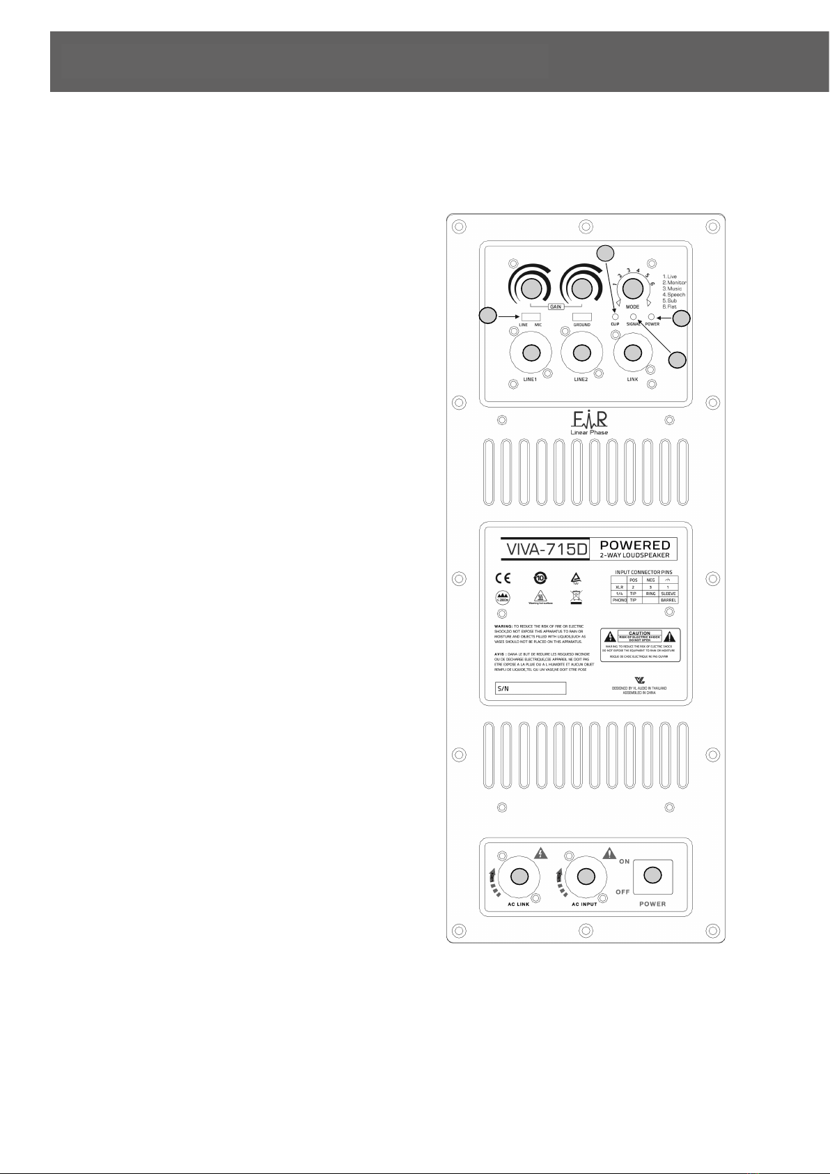
VIVA-715D
IMPORTANT NOTES
•!
•
•1 !JACK/FEMALE XLR INPUTS (BAL/UNBAL) !
The system accept jack or XLR input connectors. !
•2 !LIMITER LED!
The amplifier has a built in limiter circuit to prevent
clipping of the amplifiers or overdriving the
transducers. When the soft clipping circuit is active the
LED blinks orange. It is okay if the limit LED blinks
occasionally. If the LED blinks frequently or lights
continuously, turn down the signal level. !
•3 !SIGNAL LED!
The signal indicator lights green if there is signal p
•resent on the main XLR input !
•4 !STATUS LED!
The status indicator flash if the temperature protection
is active. !
•5 !MALE XLR SIGNAL OUTPUT!
The output XLR connector provides a loop trough for
speakers daisy chaining. !
•6 !VOLUME CONTROL !
Adjust the amplifier volume. !
•7 !MODE SWITCH!
Set the preset equalization. For all other applications
equalisation is recommended. !
•8 !INPUT SENSITIVITY SWITCH. Position the switch in
LINE to use a line level source (0 dB) or MIC to use a
microphone source. !
•9 !PowerCON AC SOCKET!
The PowerCON AC socket connect the power cord to
the socket. !
•10 !POWER MAIN SWITCH!
The power switch turns the AC power ON and OFF.
REAR PANEL FEATURES AND CONTROLS
2
1
3
4
5
8
9
10
1
6
9
6
7

CONNECTIONS
The XLR connectors use the following AES standard:
PIN 1 = GROUND (SHIELD) !
PIN 2 = HOT (+)!
PIN 3 = COLD (-)
BEFORE CONNECTING THE SPEAKER
On the back panel you will find all the controls, the signal and current inputs. At first verify that the voltage selector on the speaker is in proper
position for your country (115 Volt or 230 Volt).!
The switch shall be in proper position (unless moved from unauthorized people), but a fast check will avoid problems. In case is necessary to
change the voltage please call your vendor or authorized VL Audio SERVICE CENTRE. This operation require the substitution of the fuse value
and is reserved to an RCF SERVICE CENTRE. !
BEFORE TURNING ON THE SPEAKER
At this point you can connect the power supply cable and the signal cable, but before turning on the speaker make sure that the volume control
is at the minimum level (even on the mixer output). It is important that the mixer is already ON before turning on the speaker. This will avoid
damage to the speakers and noisy “bumps” due to turning on parts on the audio chain. It is a good practice to always turn on speakers at last
and turn them off immediately after the show.
Now you can turn ON the speaker and adjust the volume control to a proper level. !
INSTALLATION
A 35 mm socket for mounting the loudspeaker on a speaker stand is provided in the bottom of the cabinet. VL Audio speakers MUST be used
only with approved rigging hardware. !
!
WARNING: Never suspend VL Audio speakers by there handles. Handles are intended for transportation, not for rigging. !
WARNING: The use of these speakers with Stand and Pole Mount accessories can be done by qualified and experienced personnel only,
trained appropriately on professional systems installations. In any case it’s the user’s final responsibility to ensure the system safety conditions
and avoid any danger or damage to people, animals and objects. !
WARNING: To use this product with the subwoofer pole-mount, before installing the system, please verify the allowed configurations and the
indications regarding the accessories, on the VL website to avoid any danger and damages to people, animals and objects. In any case, please
assure the subwoofer which is holding the speaker is located on an horizontal floor and without inclinations. !
PROTECTIONS
VIVA Series active speakers are equipped with a complete system of protection circuits. Two led on the amplifier back panel indicate the
working status of the amplifier: the green led indicate that the speaker is ON and the red led is on when the protection circuit is active. The
circuit is acting very gently on audio signal, controlling level and maintaining distortion at acceptable level. If this led is ON for a long period is
better to reduce immediately the signal level from the mixer or from the speaker volume control. !
VOLTAGE SETUP (RESERVED TO THE RCF SERVICE CENTRE)
200-240 Volt, 50 Hz SETUP: !
FUSE VALUE T 3.15 A L 250V !
2
3
1
HOT (+)
GND (Shield)
COLD (-)
BAL. XLR
IMPORTANT NOTES
www.vlsound.com
Facebook Page : VL AUDIO
Table of contents


