Vmac A800185 User manual

1
www.vmacair.com
Owner’s Manual
A800185
VMAC Eliminator After-Cooler
2
Contents
VMAC Document Revisions……………………………………………………………………………………………………………………..1
Equipment Specifications and Accessories................................................................................................... 2
Safety ............................................................................................................................................................ 3
Installation .................................................................................................................................................... 5
Calibration/Testing ....................................................................................................................................... 7
Operation...................................................................................................................................................... 9
Drawings and Components.........................................................................................................................10
Warranty .....................................................................................................................................................11
VMAC Document Revisions
Document # 1930225
Version
Revision Details
Revised by/date
Checked by/date
Approved
by/date
Date
Implemented
A
Engineering release
MH 10 Dec 2014
MP 06 Feb 2015
RD 04 Feb 2015
03 Mar 2015
1
3
Equipment Specifications and Accessories
Air Requirements: 80CFM-185CFM
Electrical Requirements: 12V DC
Connections: 1” NPT Intake & Discharge
Accessories:
Optional mounting bracket kit: A700143
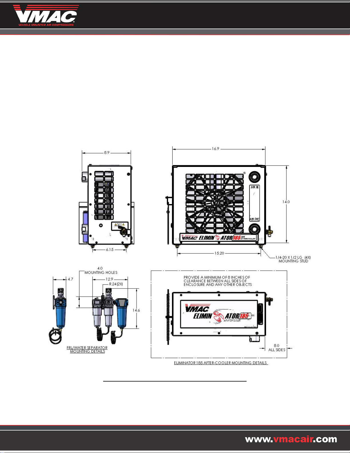
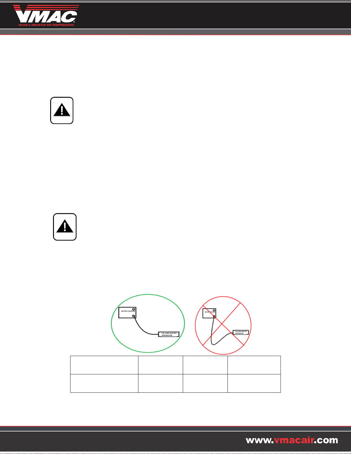
After-Cooler and FRL/Water Separator Mounting Details
2
4
Safety
Important Safety Notice
The information contained within this manual is based on sound engineering principles, research,
extensive field experience and technical information. Information is constantly changing with the
addition of new models, assemblies and service techniques. If a discrepancy is noted in this manual,
contact VMAC prior to initiating or proceeding with service. Current information may clarify the
matter. Any person with knowledge of such discrepancies who performs any work on the system,
service and repair assumes all risks.
Only proven service procedures by qualified personnel are recommended. Anyone who departs from
the specific instructions provided in this manual must first assure that their safety and that of others is
not being compromised and that there will be no adverse effects on the performance or the operational
safety of the equipment.
VMAC will not be held responsible for any liability, injuries, loss or damage to individuals or to
equipment as a result of the failure of any person to properly adhere to the procedures set out in this
manual or standard safety practices. Safety should be your first consideration in performing service
operations. If you have any questions concerning the procedures set out in this manual or require any
more information on details that are not included in this manual, please contact VMAC before beginning
any work. Our local number is 1-250-740-3200, and our toll free number is 1-800-738-8622.
To order parts, contact your VMAC dealer. Your dealer will ask for the VMAC serial number, part
number, description and quantity. To locate you nearest dealer, call 1-888-241-2289, or see our website
at www.vmacair.com and click Find a Dealer.
Safety Messages
This symbol is used to call your attention to instructions concerning your personal
safety. Read the message that follows and be aware of the possibility of injury or
death.
This symbol is used to call your attention to instructions on a specific procedure that if
not followed may damage or reduce the useful life of the compressor.
This symbol is used to call your attention to additional instructions involving fire
hazards.
Note: It is impossible to warn about every conceivable hazard; let good common sense be your guide.
3
5
Safety Precautions
Observe the following general safety rules:
Pay attention to the system during operation; do not leave it unattended
Follow safe work practices and wear appropriate safety equipment when operating air powered
equipment, particularly eye and hearing protection
Follow all safety precautions for mechanical work
Follow safety procedures for the type of work being completed
Avoid all contact with pressurized air; if it penetrates skin, it can enter the bloodstream and cause
serious bodily harm or death
Do not breathe the compressor air. Vaporized oil is a severe respiratory hazard
Avoid contact with drive belts and stay clear of all moving parts when the system is operating
To prevent compressor explosion or fire, make sure that the air entering the compressor is free of
flammable vapors
To prevent compressor explosion or fire, make sure that correct servicing procedures and intervals
are observed
Vaporized oil propelled by high pressure is an explosive mixture
4
6
Installation
Locate the Eliminator After-Cooler in a suitable location that provides good air flow and easy
accessibility. The selected location must have at least eight inches of clearance between all sides of the
Eliminator and any other objects. There should be sufficient space to connect air lines, wiring and access
the manual drain.
Ensure the Eliminator is mounted after the receiver tank if one is being used.
1. Place the Eliminator After-Cooler in position and drill the appropriate mounting holes.
2. Fasten the rubber mount feet securely. If using VMAC optional mount kit A700143, install the After-
Cooler unit to the brackets, then fasten the brackets securely.
3. Connect the supply line from the air source to the “Air In From Compressor” fitting. Support the
fitting on the Eliminator with a wrench to prevent damage.
4. Connect the delivery line to the Water Separator to the “Air Out to Water Separator” fitting. Support
the fitting on the Eliminator with a wrench to prevent damage.
5. Place the Water Separator & FRL combination unit in a position where the filters can be easily
monitored and changed then drill the appropriate mounting holes.
It is important to mount the Water Separator & FRL below the level of the After-Cooler
to improve moisture flow and prevent freeze up in cold climates.
6. Route the drain lines from the water separator and the air filter so water can drain on to the ground.
7. Connect the delivery line from the Eliminator to the water separator. Make sure the hose does not
get routed lower than the water separator. Refer to the chart below for the minimum hose diameter
allowed between after cooler and water separator. It is best practice to install the largest hose
available to reduce pressure drops across the system.
5
Compressor CFM
Up to 5 Feet
Up to 10 Feet
Up to 25 Feet
150 CFM - 185 CFM
1”
1 ¼”
1 ½”

7
8. Connect the red wire from the Eliminator After-Cooler to a key- switched 12-volt source through a
20-amp fuse using the wire size recommended in the following table.
9. Connect the green wire to a good body ground using the wire size recommended in the following
table.
Length of Wire
Recommended Wire Gauge
Less than 5 feet
14 Gauge
5 to 8 feet
12 Gauge
Over 8 feet
10 Gauge
10. Splice the white wire from the Eliminator After-Cooler to the white clutch wire at the VMAC VR
compressor using 18 gauge wire.
11. If the Eliminator After-Cooler is not used in conjunction with a VMAC VR compressor, connect the
white wire to a power source through an on/off switch using 18 gauge wire.
6
E
L
I
M
I
N
A
T
O
R
Green
Red
White
VR compressor clutch wire
20 A
12 V source
8
Calibration/Testing
1. If the truck is equipped with a VMAC VR system, place the manual transmission in neutral or the
automatic transmission in park and fully apply the park brake.
2. Start and run the engine long enough to stabilize at base idle and reach normal operating
temperature.
3. Close all compressor air system outlets.
4. Press the “ON” button on the VMAC VR system display box to engage the air compressor.
5. Verify that the fan on the Eliminator After-Cooler is running and that air is blowing out of the grill on
the front of the unit.
The unit has an auto-drain function that will vent water when it reaches a pre-determined level.
There is no operational test for this function, ensure that the system vents water during
operation.
7

9
88
8
AIR IN
FROM COMPRESSOR
AIR OUT
TO
WATER SEPARATOR / FRL
UNIT
FAN AIR FLOW DIRECTION
AIR IN
FROM COOLER
AIR OUT
TO AIR TOOLS

10
Operation
If the Eliminator is correctly wired into the compressors on/off switch there will be no required
manual input to activate or deactivate the Eliminator fan.
If the Eliminator is installed on a separate compressor and using an auxiliary switch for activation,
this switch should be turned on as soon as the compressor is turned on. The fan should then be
turned off when the compressor is turned off.
At the end of the day or shift, shut the compressor system down, vent the air, then open the manual
drain valve on the side of the cooler to drain the air line of moisture to avoid freeze-up in cold
weather. Leave the valve open until you are ready to start the compressor again.
To avoid freeze up in cold climates it is critical that the system is completely
discharged after each use using the manual drain on side of Eliminator.
This allows the water separator to completely drain out the moisture preventing ice
damage to the internal components.
During daily operating the inlet air fitting can become very hot, never touch the inlet
fitting with your bare hands without allow sufficient cooling down of the unit.
9

11
Drawings and Components
10
ITEM.
QTY.
PART#
DESCRIPTION
8
4
1500596
VIBRATION MOUNT,NAT RUBBER, 1/4-20
9
4
1570499
WASHER, FLAT, THICK, SS 1/4
10
4
1550527
NUT, NYLOK, S/S, 1/4-20
11
2
3200446
ADAPTOR, AFTERCOOLER, 185
12
1
6000659
SHROUD, FAN, AIR DRYER
13
6
1500595
RIVET, ALU, STANDARD, BLIND 1/4"
14
2
2200133
CLAMP, INSULATED DOUBLE TUBE, 1/4
15
4
1520627
BOLT, HHCS, FL, PL, M8 X 1.25 X 20
16
1
1500631
SCREW, PHMS, M5 X 8
17
1
5000168
VALVE, MANUAL DRAIN
18
2
5830116
O-RING, VITON, ORB-16
19
1
3550891
HARNESS, FAN, A800185
20
1
3600124
COOLER, #16 ORB PORTS
21
1
3501070
FAN, 11" PUSHER 12V
22
6
1570163
WASHER, FLAT, 3/16
23
6
1550524
NUT, NYLOCK, 10-32
ITEM.
QTY.
PART#
DESCRIPTION
1
1
6000456
TRAY, BASE ,AIR DRYER
2
1
6000458
COVER, AIR DRYER
3
2
1500598
RIVET, ALUMINUM, CLOSED END, 1/8"
4
1
6000457
PANEL, REAR ,AIR DRYER
5
34
1500587
SCREW,SL,MC IND HEX 10-32 X 5/8-SS
6
34
1570488
WASHER, NYLON, 3/16
7
1
6000455
PANEL, FRONT ,AIR DRYER
ITEM.
QTY.
PART#
DESCRIPTION
1
1
3600162
FILTER, MOISTURE SEPARATOR, 185
2
1
4900205
NIPPLE, HEX, 1 NPT
3
1
3600161
ASSEMBLY, FRL, 185 CFM
4
36”
1700055
HOSE, BRAKE BLACK, 1/4
5
36”
1700630
HOSE, DRAIN, 1/4" ID
6
1
2200229
CLAMP, SPRING, 5/16 OD
2
3
4
1
7
5 6
8
9
10
11 18
12 13
14
15 16
17
19
20
21
23 22
1
2
3
4
6
5

12
Warranty
GENERAL PROVISIONS AND LIMITATIONS
VMAC, Division of Mangonel Investments Corporation, (hereafter ”VMAC”) warrants to each original retail purchaser (hereafter “Buyer”) of its
new Accessory Product (hereafter “Product(s)”) from VMAC or its authorized Dealers that such Product(s) are, at the time of delivery to the
Buyer, free of manufacturer defects in material and workmanship.
NO WARRANTY IS MADE WITH RESPECT TO
Any Product(s) which have, in VMAC’s judgment, been subject to negligence, accident or improper storage, installation, application, operation
or maintenance, or have been repaired or altered in such a way that affects the Product(s) adversely.
Components or accessories manufactured, warranted and serviced by others.
Damages caused from service and repairs and corrections with minimum action, such as adjustments and inspections, or replacement of items.
Consequential damages caused by Product(s) failure.
Any Product(s) if other than VMAC’s genuine components are used in the Product(s).
Normal wear and tear of Product(s).
WARRANTY PERIOD
The warranty period will commence 30 days from date of shipment from VMAC.
The Product(s) is warranted against manufacturer defects in materials and workmanship for a period of 12 months.
Replacement components of Product(s), shall be warranted for the remainder of the original warranty period.
VMAC OBLIGATIONS
VMAC’s obligation is limited to repairing or, at VMAC’s option, replacing, during normal business hours at an authorized service facility of
VMAC, any component, which in VMAC’s judgment is proven to be defective as warranted.
VMAC’s obligation is limited to Product(s) proven to be warranted. No liability is accepted for any consequential damages, injuries or expenses
directly or indirectly related to Product(s) failure.
BUYER OBLIGATIONS
Buyer shall notify VMAC of the alleged defect within 10 days of initial discovery and return the allegedly defective component(s) within 30 days
of initial discovery.
The Buyer must prepay all costs associated with the warranty claim and submit receipts and/or invoices to VMAC for evaluation.
If required by VMAC, the Buyer must return components claimed under this warranty to a facility designated by VMAC for evaluation, to
establish a claim under this warranty.
DISCLAIMER AND WARRANTY SERVICE
Any labor costs claimed in excess of VMAC’s set rate and/or times are not provided by this warranty. If applicable, any labor costs in excess of
VMAC rate schedules caused by, but not limited to, location or inaccessibility of the equipment, travel time or labor provided by unauthorized
service personnel are not provided by this warranty.
This warranty is in lieu of all other warranties or obligations, express or implied. VMAC expressly disclaims all implied warranties of
merchantability or fitness for a particular purpose.
Warranty claims must be pre-authorized by VMAC, and the components returned via prepaid freight using the designated “Returned
Merchandise Authorization” number and form
11
Other manuals for A800185
1
Table of contents
Other Vmac Accessories manuals


