Vmac VR70 User manual

System V900075
1999 - 2003.25 Ford F-250 - F-550 Super Duty
7.3L Power Stroke Diesel
www.vmacair.com
VR70 UNDERHOOD
AIR COMPRESSOR
INSTALLATION MANUAL


VMAC – Vehicle Mounted Air Compressors
Toll Free: 1-800-738-8622
Fax: 1-250-740-3201 1
Installation Manual for VMAC
System V900075
Ford 1999 – 2003.25
7.3L Power Stroke Diesel
F250-F550 Super Duty
General Information..................................................................... 3
Before You Start....................................................................... 3
Special Installation Notes......................................................... 4
Part 1: Preparing for Installation............................................... 6
1.1 Preparing for Installation .................................................... 6
Part 2: Installing the Tank and Hoses....................................... 9
2.1 Installing the Tank and Frame Mounts............................... 9
2.2 Attaching Hoses to the Tank.............................................. 14
Part 3: Installing the Main Bracket and Compressor.............. 15
3.1 Oil Cooler Installation Exceptions....................................... 15
3.2 Installing the Oil Cooler...................................................... 15
3.3 Installing the Pulley and Bracket........................................ 16
3.4 Installing the Compressor................................................... 18
3.5 Adding Oil to the System.................................................... 20
Part 4: Installing the Control Components .............................. 21
4.1 Installing the Control Unit................................................... 21
4.2 Installing the Throttle Control ............................................. 22
4.3 Connecting the Wiring........................................................ 22
4.4 Completing and Testing the Installation............................. 34

VMAC – Vehicle Mounted Air Compressors
Toll Free: 1-800-738-8622
Fax: 1-250-740-3201
2
Installation Manual - Document #1930058
Installation Manual for VMAC System V900075
Ford 1999-2003.25 7.3 L Power Stroke Diesel
F250-F550 Super Duty
Changes and Revisions
Version Revision Details Revised by/date Approved by/date Implemented
00 Original Manual IB 27 Jan 2004 SC 14 Mar 2004 18 Mar 2004
A Revisions IB 18 June 2006 SM 20 June 2006 22 June 2006
B ECN 07-145 IB 05 Nov 2007 SH 23 Nov 2007 26 Nov 2007
Important Information
The information in this manual is intended for certified VMAC
installers who have been trained in installation procedures and for
people with mechanical trade certification who have the tools and
equipment to properly and safely perform the installation. Do not
attempt this installation if you do not have the appropriate
mechanical training, knowledge and experience.
Follow all safety precautions for underhood mechanical work. Any
grinding, bending or restructuring operations for correct fit in modified
trucks must follow standard shop practices.
These instructions are a general guide for installing this system on
standard production trucks and do not contain information for
installation on non-standard trucks. This system may not fit special
order models or those which have had other changes without
additional modifications. If you have difficulty with the installation,
contact VMAC.
The VMAC warranty form is located at the back of this manual. This
warranty form must be completed and mailed or faxed to VMAC at
the time of installation for any subsequent warranty claim to be
considered valid.
To order parts, contact your VMAC dealer. Your dealer will ask for
the VMAC serial number, part number, description and quantity. To
locate your nearest dealer, call 1-800-738-8622.
Copyright 2007
All trademarks used in this manual are the property of the respective copyright holder.
The contents of this manual may not be reproduced in any form without the express
written permission of VMAC, 1333 Kipp Road, Nanaimo, BC V9X 1R3.
Printed in Canada

VMAC – Vehicle Mounted Air Compressors
Toll Free: 1-800-738-8622
Fax: 1-250-740-3201 3
General Information
Before You Start
Read this manual before attempting installation so that you can
familiarize yourself with the components and how they fit on the
truck. Identify variations for different model years and different
situations that are listed in the manual. Open the package, unpack
the components and identify them.
All fasteners must be torqued to specifications. Use manufacturers
torque values for OEM fasteners. Apply Loctite 242 or equivalent on
all engine-mounted fasteners. Torque values are with Loctite applied
unless otherwise specified.
STANDARD GRADE 8 NATIONAL COARSE THREAD
Size 1/4 5/16 3/8 7/16 1/2 9/16 5/8 ¾
Foot-pounds (ft-lb) 9 18 35 55 80 110 170 280
Newton meter (N•m) 12 24 47 74 108 149 230 379
STANDARD GRADE 8 NATIONAL FINE THREAD
Size 3/8 7/16 1/2 5/8 ¾
Foot-pounds (ft-lb) 40 60 90 180 320
Newton meter (N•m) 54 81 122 244 434
METRIC CLASS 10.9
Size M8 M10 M12 M14 M16
Foot-pounds (ft-lb) 19 41 69 104 174
Newton meter (N•m) 25 55 93 141 236
Hose Coding
Different frame designations will affect the tank mounting position.
You may have to move the tank rearward from the standard position
on your application. If you must move the tank, the lines may be too
short. If this is the case, measure the hose shortfall and order a
Hose Extender Kit. The following table shows the color code used
by VMAC to define the different hose diameters.
Hose Diameter Colour-Coded Label
1/2 inch
5/8 inch
3/4 inch
1 inch
Blue
Blue
Green
Green
Special Installation Notes
2001-2003.25 trucks will require accessory kit A700121
1999-2001.25 trucks will require accessory kit A700120
System Identification Number Plate
The enclosed System Identification Number Plate must be attached
to the vehicle at the time of installation. This plate provides
information which allows VMAC to assist in customer inquiries and
the ordering of parts. Mark and drill two 7/64 inch holes, then secure
the plate with two #6 pan head self-tapping screws.
SystemIDnumberplate
Left Front
Safety Decal
As part of the installation process, ensure that the safety and
operational instruction decal is affixed in an obvious location so that
it can be seen by vehicle operators.
Daily Pre-Start Check Start Up Procedure Shutdown Procedure
This Vehicle is Equipped with a VMAC Air Compressor System
1. Check Oil Level in Tank
2. Check Drive Belt
3. Check for Leaks
1. Allow engine to idle for 1 minute
2. Turn OFF compressor
3. Wait for system to discharge
for 1 minute before restarting
1. Ensure Compressor is OFF
2. Ensure discharge valve is
CLOSED
3. Ensure air system is discharged
4. Place vehicle in Neutral or
Park and engage vehicle
safety features - park brake
5. Start engine and bring up to
operating temperature
6. Turn ON compressor
For Technical Support/Parts contact your VMAC Dealer
To locate your nearest dealer call 1-800-738-8622 (250-740-3200)
OPERATING INSTRUCTIONS
Always allow system pressure to discharge before restarting
WARNING
!
VMAC – Vehicle Mounted Air Compressors
Toll Free: 1-800-738-8622
Fax: 1-250-740-3201
4
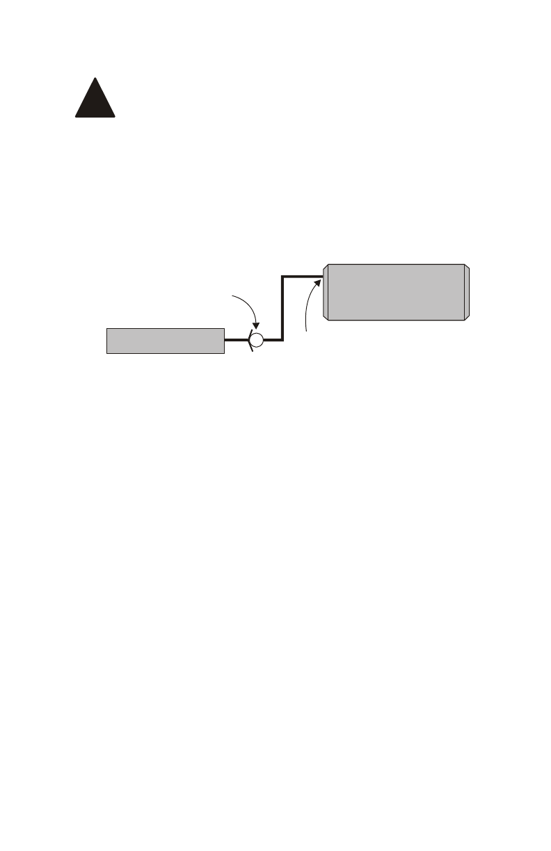
Auxiliary Air Receiver
If you intend to use an auxiliary air receiver with this
system you must observe the following installation
procedure to prevent damage to the system.
!
The line from the VMAC tank to the auxiliary air receiver must have a
one-way check valve installed to prevent blow back from the auxiliary
tank to stop moisture from entering the VMAC tank.
The line to the auxiliary tank must not be installed in the bottom of
the tank, but must be installed as high as possible to prevent water
from entering the line.
Install the line as high as
possible, NOT on the
bottom of the auxiliar
y
tank
VR Tank
One-way check valve
A
uxiliary Tank
VMAC – Vehicle Mounted Air Compressors
Toll Free: 1-800-738-8622
Fax: 1-250-740-3201 5

VMAC – Vehicle Mounted Air Compressors
Toll Free: 1-800-738-8622
Fax: 1-250-740-3201
6
Part 1: Preparing for Installation
1.1 Preparing for Installation
1. Disconnect the battery and remove it from the vehicle.
2. Drain the coolant.
3. Remove the OEM fasteners from the coolant expansion bottle
and move it out of the way. Do not disconnect the hoses from the
bottle.
4. Remove the left intercooler tube from between the engine and
the intercooler.
5. Remove and discard the plastic cover and attaching nuts from
the center top area of the engine.
6. Remove the OEM belt, cooling fan and the fan shroud.
7. Disconnect the air inlet horn from the front of the air cleaner and
battery box, but leave it in place. Remove the air cleaner box and
the battery box.
8. Remove the alternator from its mount and lay it back on top of
the engine. Keep the OEM fasteners.
9. Mark the position of the power steering pump pulley in
relationship to the shaft and remove the pulley using an
approved puller.
10. Remove the power steering pump from the bracket. Keep the
OEM fasteners. Fasten the pump out of the way on the frame.
11. Remove and discard the power steering return hose from the
power steering pump.
12. Remove and discard the OEM alternator and power steering
pump mounting bracket. Keep the fasteners.
13. Remove the upper and lower radiator hoses.
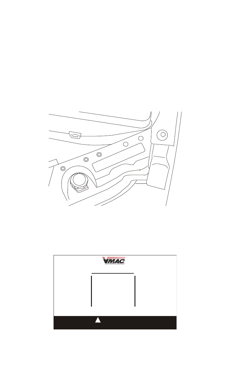
14. Exchange the forward right bolt and rear left stud on the
aluminum cover at the top front of the engine (Figure 1.1).
Exchange these two fasteners
Front
Figure 1.1
15. Remove and discard the 12 mm stud and nut (lower right side of
the engine) and the 12 mm bolt (lower left side of the engine)
which retain the ground straps (Figure 1.2).
M12 stud holding ground strap
and transmission cooling lines
M12 hex head cap scre
w
holding ground strap
Figure 1.2
16. Remove and discard the positive battery cable locating bracket
from the same area.
VMAC – Vehicle Mounted Air Compressors
Toll Free: 1-800-738-8622
Fax: 1-250-740-3201 7

VMAC – Vehicle Mounted Air Compressors
Toll Free: 1-800-738-8622
Fax: 1-250-740-3201
8
17. Clean the front of the engine block to ensure that the oil cooler
and mounting bracket will fit flush.
18. Clean the driver’s side frame.
19. Remove the three OEM bolts from the crankshaft pulley.
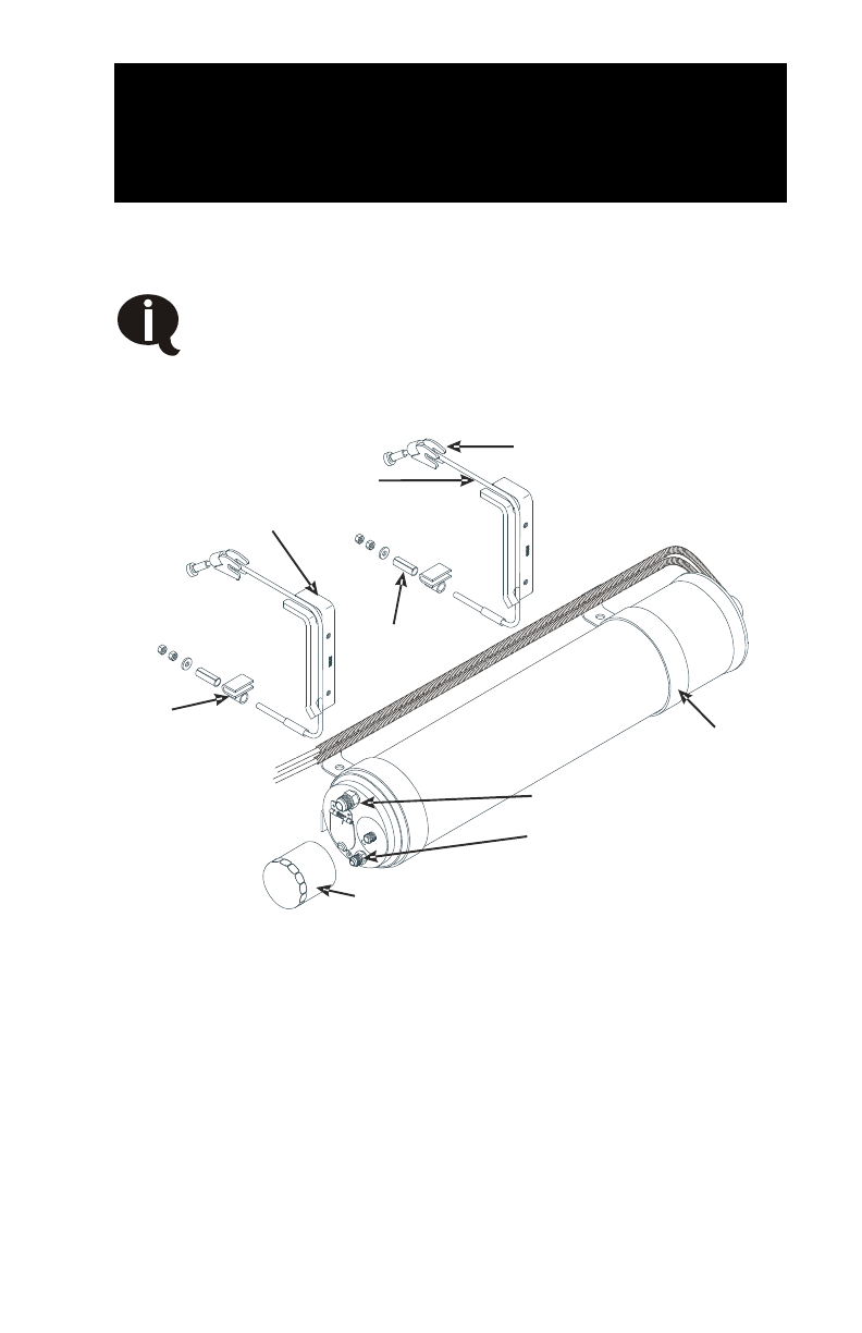
Part 2: Installing the Tank and
Hoses
The tank will mount on the driver side frame rail behind the front cab
mount.
Apply Loctite to all fasteners before installing them.
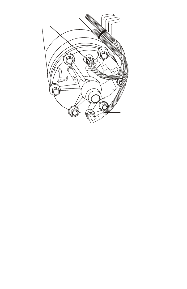
2.1 Installing the Tank and Frame Mounts
3/4” hose fitting
1/2” hose fitting
C-clam
p
Tank strap mount
Upper frame clip
Tank strap cable
Lower
frame
clip
Spacer for
F250-F350
Oil filter
1/4 and 3/16” tubes
Figure 2.1
1. Remove the pinch bolts from the C-clamps, spread the clamps
slightly and slide them over the front of the tank.
2. Rotate the C-clamps so that the flat mounting surfaces are on
the right side of the tank, as viewed from the back of the tank
(Figure 2.2).
VMAC – Vehicle Mounted Air Compressors
Toll Free: 1-800-738-8622
Fax: 1-250-740-3201 9
3/16” tube
1/4” tub
e
Figure 2.2
3. Insert the pinch bolt from the top, then install the washer and nut,
but do not tighten.
4. Place a tank strap mount against the one of the C-clamps on the
tank with the short arm (or “L”) at the top of the tank, facing away
from the tank. Install a 5/16 x 1/2 inch bolt with flat washer into
the bottom hole. Do not tighten.
5. Insert the second bolt through the top hole in the C-clamp and
into the top hole on the tank strap mount. Do not tighten.
6. Repeat this procedure with the second strap mount bracket and
C-clamp.
7. Identify the tank mounting position which matches the vehicle
(Figure 2.4). These locations are suggestions only.
VMAC – Vehicle Mounted Air Compressors
Toll Free: 1-800-738-8622
Fax: 1-250-740-3201
10

F250 & F350 standard cab 2x4 and 4x4
F450 & F550 standard cab 2x4 and 4x4
F250 & F350 super cab 2x4 and 4x4
F450 & F550 super cab and crew cab 2x4 and 4x4
Front cab mount
Front cab mount
Front cab mount
Front cab mount
19.25
16.25
17.25
16.25
17.25
1.25
11.75
Transfer case
Figure 2.4
8. Remove the nuts and washers from the threaded end of the tank
strap cables, insert them through the end of each tank flat bar
strap with the single hole and pull them to the stops.
VMAC – Vehicle Mounted Air Compressors
Toll Free: 1-800-738-8622
Fax: 1-250-740-3201 11

9. Place the tank strap cables over the frame rail from the inside of
the frame, with the tank flat bar strap on the inside of the rail and
the tank strap cables hanging over the top outer edge of the
frame rail (Figure 2.5).
10. Support the tank and assembly in place on the outside of the
frame, with the short part of the tank mount strap positioned over
the top of the frame.
11. Pass each tank strap cable around the tank mount strap,
between the strap and the tank. Make sure that the tank strap
cable fits between the cable guide and the C-clamp (Figure 2.5).
Cable must fit
in the grooves
Figure 2.5
When positioning the tank on the frame, make sure that
the mounting location will not pinch or damage any
wiring harnesses, lines or hoses.
!
12. Insert the threaded end of each cable strap through the tubes on
the lower frame locating U-clips. A special clip is included for
trucks with double frames.
VMAC – Vehicle Mounted Air Compressors
Toll Free: 1-800-738-8622
Fax: 1-250-740-3201
12

13. Install the appropriate spacer and nut combination:
•F250 and F350 trucks (all models) install the 1/8 inch thick
5/16 x 3/4 inch washers, the 1/2 x 2 inch spacer and the 5/16
inch nuts.
•F450 & F550 trucks (all models) install the 1/8 inch thick
5/16 x 3/4 inch washers and the 5/16 inch nuts. Discard the
1/2 x 2 inch spacer
14. Thread a 5/16 inch nut on each tank strap cable and tighten the
nuts enough to hold the tank in position.
15. Check the dimensions in Figure 2.4 to ensure that the positioning
is correct for the appropriate model. On the F450 & F550
standard cab models (2x4 and 4x4) position the rear tank
bracket assembly so that the front edge of the tank flat bar strap
is approximately 1-1/4 inches back from the forward edge of the
cut-out for the transfer case.
Make sure that
the threaded end of the tank strap cable
is not positioned next to the transfer case housing, as
torque movement will cause the transfer case housing
to strike the threaded end of the securing cable.
!
16. When the tank is correctly positioned, tighten the tank strap
cable retaining nuts until the cables pull tight and snug around
the frame. Do not over-tighten the nuts.
17. Install a second 5/16 inch nut and tighten it securely against the
first to act as a locknut.
18. Check the alignment of the tank to make sure that the “UP”
arrow on the end of the tank points directly upward and that the
tank is aligned correctly, then tighten the C-clamp pinch bolts
securely, but not so much as to distort the mounting surfaces.
Improper installation can result in an extremely
hazardous situation, causing injury or equipment
damage .
!
19. Remove each of the bolts (one at a time) holding the C-clamp to
the tank strap mount, apply Loctite and replace the cap screws.
20. Make sure that the tank is level with the vehicle and tighten the
bolts.
VMAC – Vehicle Mounted Air Compressors
Toll Free: 1-800-738-8622
Fax: 1-250-740-3201 13

VMAC – Vehicle Mounted Air Compressors
Toll Free: 1-800-738-8622
Fax: 1-250-740-3201
14
2.2 Attaching Hoses to the Tank
1. Route the straight end of the 3/4 inch hose over the cab mount
and thread it into the top fitting on the tank but do not tighten.
2. Route the straight end of the longest 1/2 inch hose over the cab
mount and thread it onto the lower fitting on the front of the tank
but do not tighten.
3. Insert the 1/4 and 3/16 inch tubes into the fittings on the back of
the tank and cover them with high temperature loom. Route the
tubes through the frame up to the compressor and connect them
to the matching fittings on the compressor inlet valve.
4. Bunch all hoses together and protect them where they pass over
the cab mount.
5. Route all the hoses and tubes into the engine compartment.

Part 3: Installing the Main Bracket
and Compressor
Apply Loctite to all fasteners before installing them.
3.1 Oil Cooler Installation Exceptions
Vehicles manufactured prior to Ford model year 2001.75
(Calendar year April 2001) must have the lower 90 deg
coolant spigot (RH65) removed from the engine and
replaced with the supplied straight spigot. On vehicles
with dual alternators, install the supplied alternate leg
before the cooler.
1. Remove the 5/16 NC bolts and nuts that fasten the passenger
side cooler mounting bracket to the back of the cooler and
discard the bracket.
2. Facing the front of the cooler, install the alternate leg so that the
hook shape at the top faces left and the spacers on the adaptor
face the cooler.
3. Use the supplied 5/16 x 1-1/4 inch NC bolts to fasten the
alternate leg to the cooler with the existing washers and Nylok
nuts. Torque to specifications.
3.2 Installing the Oil Cooler
1. Fit the cooler in place under the crankshaft pulley, over the two
studded fasteners at the front of the engine block (Figure 3.1).
2. Attach the transmission lines to the right hand stub. This may
require the bracket to be bent or modified slightly.
3. Install the ground cable, thread on two M10 Nylok nuts and
tighten.
VMAC – Vehicle Mounted Air Compressors
Toll Free: 1-800-738-8622
Fax: 1-250-740-3201 15
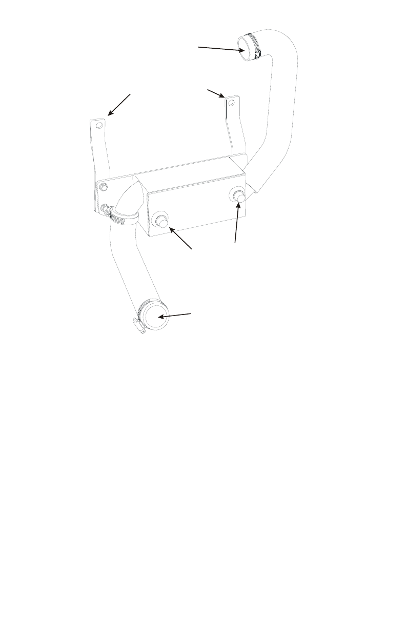
Hose to Engine Block
Hose to Radiator
Hose Fittings
Mounting Brackets for
Attaching to the Engine
Figure 3.1
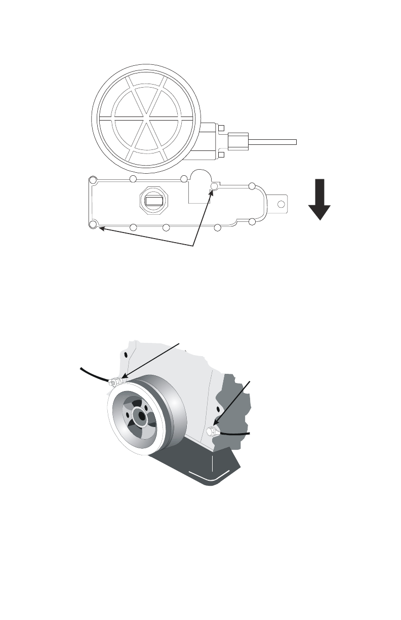
3.3 Installing the Pulley and Bracket
1. Clean all dirt and debris from the face of the OEM pulley before
installing the pulley.
2. Install the compressor pulley using three supplied M10 x 20 mm
socket head bolts. Torque to specifications.
3. Remove the idler and tensioner from the main bracket.
4. Install the main compressor mount bracket using the four OEM
flange lock bolts. Torque them to specifications (Figure 3.2).
5. Install the power steering pump to the main bracket using the
OEM fasteners.
VMAC – Vehicle Mounted Air Compressors
Toll Free: 1-800-738-8622
Fax: 1-250-740-3201
16
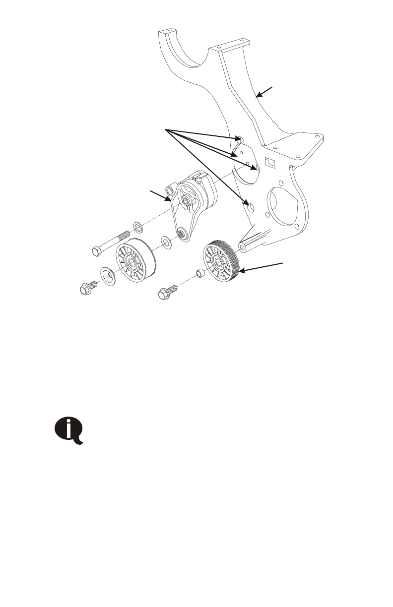
Main bracket
Ribbed idler
Tensioner
OEM bolt locations
Figure 3.2
6. Align the marks and install the power steering pump pulley. The
outer edge of the power steering pump pulley must be flush with
the end of the pump shaft.
7. Install the alternator onto the main bracket using the OEM
fasteners.
The alternator must be mounted 180 degrees (upside-
down) from the original mounting position. Rotate the
alternator 180 degrees counterclockwise.
8. Install the supplied 3/8 x 36 inch power steering return hose
between the power steering pump and the master cylinder.
9. Align the power steering hoses to clear the steering column.
VMAC – Vehicle Mounted Air Compressors
Toll Free: 1-800-738-8622
Fax: 1-250-740-3201 17

3.4 Installing the Compressor
1. Place the compressor onto the main bracket and fasten it in
place using the three supplied 8 mm double serrated lock nuts.
Torque to specifications.
2. Install the idler and tensioner and torque the fasteners to
specifications.
3. Install the OEM (Figure 3.3) and compressor belts (Figure 3.4)
Crankshaft pulley
Power steering
Water pump
A
lternator
Idler
Idler
Tensioner
Air conditioning
Figure 3.3
VR70
Crankshaft
Pulle
y
VR70
Tensioner
V
R7
0
Air
Compressor
VR70
Idler
V
R70
Drive Bel
t
Figure 3.4
VMAC – Vehicle Mounted Air Compressors
Toll Free: 1-800-738-8622
Fax: 1-250-740-3201
18
Other manuals for VR70
24
Table of contents
Other Vmac Air Compressor manuals

Vmac
Vmac V300004 User manual

Vmac
Vmac VR70 User manual

Vmac
Vmac Underhood 70 User manual

Vmac
Vmac DM00030 User manual

Vmac
Vmac UNDERHOOD 40 Series User manual

Vmac
Vmac DM00021 User manual

Vmac
Vmac UNDERHOOD 40 Series User manual

Vmac
Vmac PREDATAIR User manual

Vmac
Vmac UNDERHOOD 40 Series User manual

Vmac
Vmac DM2A021 User manual

Vmac
Vmac VR70 User manual

Vmac
Vmac H400005 Installation instructions

Vmac
Vmac Underhood 70 User manual

Vmac
Vmac V400001 User manual

Vmac
Vmac UNDERHOOD 40 Series User manual

Vmac
Vmac PredatAir Series Specifications

Vmac
Vmac G300005 User manual

Vmac
Vmac H400016 Installation instructions

Vmac
Vmac V900140 User manual

Vmac
Vmac UNDERHOOD 40 Series User manual


