Vmed Technology BP-AccuGard User manual

Vmed Technology
BP-AccuGard
TM
Blood Pressure
Monitor
with
PC-DISPLAY
software
User Manual
1
ACCESSORIES AND COMPONENTS
Check packaging and ensure the following standard items are included
• BP-AccuGard Monitor
• Storage pouch
• 6 cuffs (# , 2, 3, 4, 7, 8)
• 8 ft. airline
• Quick-Start Manual
• Software Manual (if Bluetooth included)
• PC-Display install CD (if Bluetooth included)
• Bluetooth USB Adaptor (if Bluetooth included)
PRECAUTIONS
o CAUTION: Use only the patient isolated battery charger provided by Vmed.
Laptop charging plugs may appear identical but the use of these on the BP-
AccuGard may damage electronics and voids the warranty.
o Do not operate or mount the BP-AccuGard on its side. Vertical mounting is
OK.
o BP-AccuGard not registered with the FDA for human use.
o Do not use in the presence of flammable anesthetics.
o Do not immerse the BP-AccuGard, or cables in water or other fluids. Avoid
spilling fluids on the BP-AccuGard or accessories.
o Do not autoclave the BP-AccuGard or accessories.
o Do not disassemble the BP-AccuGard enclosure. It contains no operator
serviceable components and opening the enclosure voids the warranty.

2
Table of Contents
Chapter 1 Description and Stand-Alone Mode .................................................................. 3
Monitor Description ......................................................................................................... 3
Stand-Alone Mode .......................................................................................................... 4
Device Interface .............................................................................................................. 4
Top Panel .................................................................................................................. 4
Description of Controls and Indicators ....................................................................... 5
Connector Panel ........................................................................................................ 6
Preparation ......................................................................................................................
Manual Measurement ..................................................................................................... 8
Chapter 2 Computer Connected Mode ........................................................................... 20
The PC-Display Screen ................................................................................................. 20
Pulse Rate Display .................................................................................................. 23
Blood Pressure Display ............................................................................................ 23
Status Display .......................................................................................................... 24
Cuff Pressure Waveform Display ............................................................................. 25
Oscillometric Waveform Display .............................................................................. 25
Controlling Measurements with PC-Display .................................................................. 26
Controlling Measurements from the BP-AccuGard ....................................................... 32
Recording Measurements ............................................................................................. 35
Chapter 3 Configuration Options .................................................................................... 36
Device Configuration ..................................................................................................... 36
PC-Display Configuration .............................................................................................. 42
Chapter 4 Service and Maintenance .............................................................................. 48
Service and Support ...................................................................................................... 48
Cleaning and Maintenance............................................................................................ 49
Cleaning ................................................................................................................... 49
Maintenance ............................................................................................................ 49
Charging the Battery ................................................................................................ 49
Device Error Messages ................................................................................................. 49
Troubleshooting Guide .................................................................................................. 52
Appendix A Limited Warranty ......................................................................................... 53
Appendix B Accessories and Replacement Parts ........................................................... 56
3
Chapter 1 Description an Stan -Alone Mo e
The BP-AccuGard is a digital oscillometric blood pressure monitor optimized for
small animals. Oscillometric devices measure the oscillation of the vessel wall as
the cuff deflates. The BP-AccuGard uses sophisticated algorithms to calculate the
blood pressure measurements from these oscillations based on the pressure in the
cuff. While all oscillometric devices have limitations especially with patient
movement and the relatively small size of arteries in small animals the BP-
AccuGard software is successful in significantly reducing motion artifacts resulting
in faster more accurate measurements. Accurate measurements are possible on
patients under anesthesia as small as 1.5 kg. Measurements are displayed on the
device or on a computer screen when used in conjunction with Bluetooth hardware
and PC-Display software.
Monitor Description
The BP-AccuGard is a small, table-top device powered by a rechargeable LI-ion
battery with built-in digital display. An optional Bluetooth configuration is available
for wireless connection to a Windows computer for the real-time display of pressure
waveforms and digital measurements.
The BP-AccuGard includes manual and automatic modes for diagnostic and surgical
applications. In manual mode, measurements take place when initiated by the
operator as desired. Automatic mode allows repeat measurements taken at user-
defined intervals. Motion tolerant software reduces the computational time for
awake animals without compromising accuracy.
Use the BP-AccuGard as a stand-alone blood pressure monitor or use the optional
PC-Display software and Bluetooth wireless link to display measurements, real-time
blood pressure waveforms and a trend graph on your computer screen. PC-Display
software can store the measurements for the surgical or diagnostic record and these
files can be attached to patient records in most practice management programs.
Chapter
1

4
Print reports using your computer or network printer or automatically attached to an
E-mail message.
Included with the BP-AccuGard is a power supply cord for recharging the internal
battery, an airway hose and a set of six cuffs.
Stan -Alone Mo e
The BP-AccuGard can be used as a “standalone” monitor where blood pressure
measurements are performed on the patient without any computer interaction.
Chapter 1 will describe this mode of operation and describe the steps necessary to
perform such measurements
.
Device Interface
The description the user interface, controls and indicators are described.
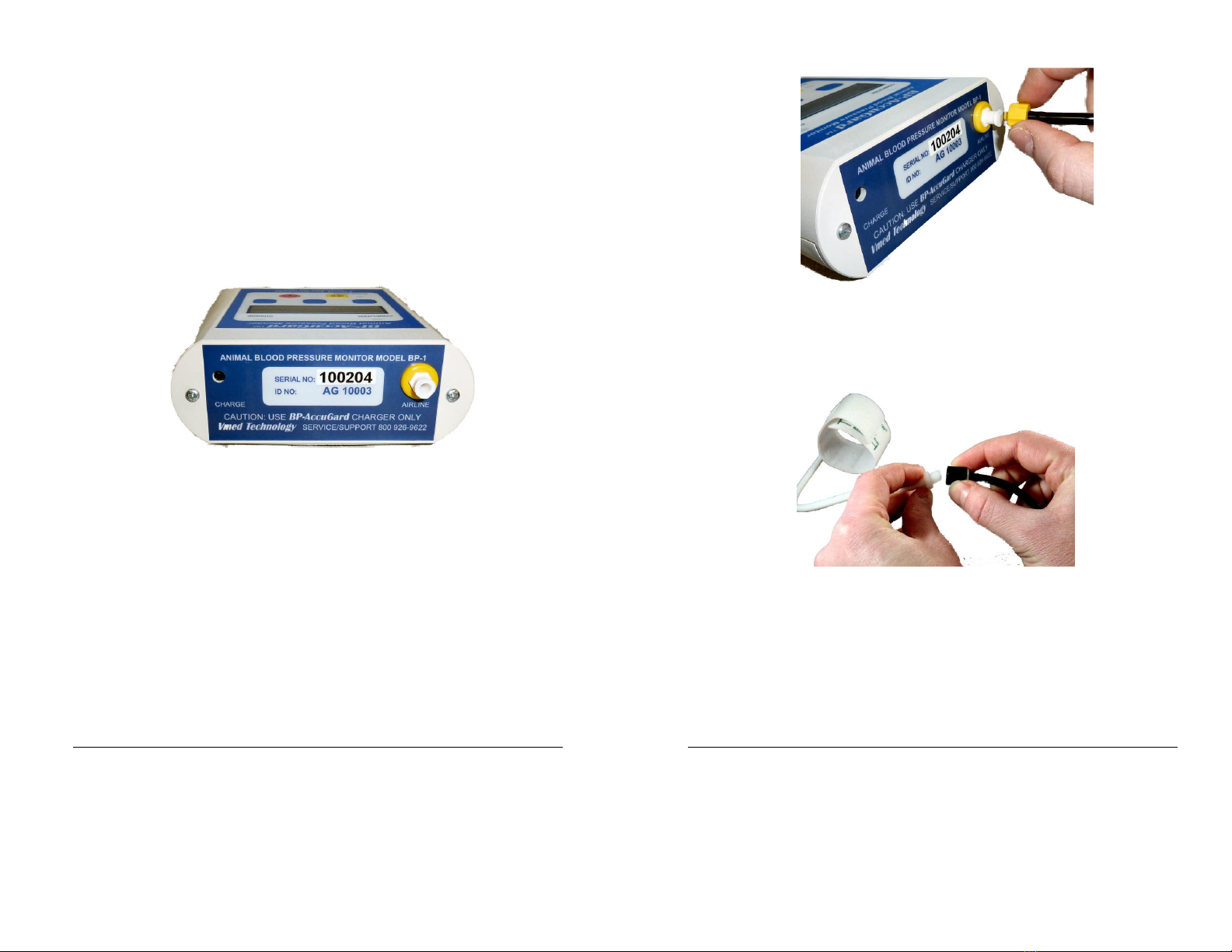
Top Panel
The top panel includes the character display, indicator and the keypad as shown
below.
Figure Top panel with display, indicator lights and keypad
5
Description of Controls an In icators
In icator Lights (LEDs)
COMPUTER
The computer LED will only be functional on units with the
Bluetooth option installed. When power is applied, the computer
LED will first turn red and then after a moment turn amber (also
described as orange or yellow). The amber color indicates that the
BP-AccuGard is in its Bluetooth standby state, waiting for a
computer connection. Once the wireless connection is made the
LED will begin flashing green.
CHARGE
The CHARGE LED illuminates only when the power supply cord is
plugged into the remote. The LED will be amber when the battery
is charging and green when the battery is fully charged.
ALARM ON/OFF
The ALARM ON/OFF LED and its corresponding button are not
functional when the remote is connected to a computer. In
stand-alone mode, this LED illuminates when the unit’s alarm
tone is enabled.
Display (Also LCD Display)
The 6 digit, 2-line digital display near the middle of the top panel shows the various
options, commands and measurements for the device. The bottom row of the
display often shows the various commands available using the three corresponding
“soft keys” beneath the display.
Keypa Buttons
SELECTION KEYS
The three blank buttons beneath the Display correspond directly
to each of the different command options shown on the bottom
line of the display. These buttons are referred to as “keys” in this
manual. The left, middle and right keys relate to the command
option shown directly above each key on the bottom line of the
Display.
6
ALARM
The yellow “Silence Alarms” button with an image of a speaker
enables and disables the alarm audio. Pressing this button will
toggle this alarm on and off.
NOTE: Alarms must be enabled in
the configuration menu to be operative
POWER
Press and immediately release the power button to turn the BP-
AccuGard on. Press and hold this button down to turn the device
off. If the BP-AccuGard is equipped with Bluetooth, turning the
device on will also power up Bluetooth.
Connector Panel
The connector panel includes the battery charge port and the blood pressure hose
receptacle as shown below.
Figure 2 Connector panel
CHARGE
Plug the power supply/battery charge adapter in to charge the
battery.
CAUTION: Use the power supply adapter provided with
the BP-AccuGard ONLY Use of any other power supply adapter
could damage the unit and void the warranty
AIRLINE
Connect the blood pressure airline to this receptacle. Use the
proper end of the airline and screw in securely.
ID NO
The number beneath the device Serial number identifies the
unique BP-AccuGard that will link wirelessly to your computer.
See the PC-Display User’s Manual for more details.
7
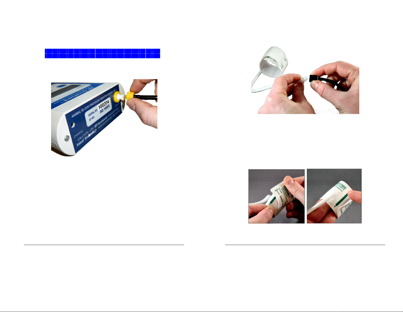
Preparation
Figure 3 Connecting airline to monitor
.
Connect the airline to the monitor and to a cuff of appropriate size for the
patient by screwing the correct end of the airline onto the cuff receptacle.
Figure 4 Connecting cuff to airline
2.
Wrap the cuff around the leg or base of tail so that the artery reference mark
on the cuff is over the vessel and fits within the range marks on the cuff. The
cuff should not be loose around the patient. Select a different cuff when the
artery line does not fall within the range marks.

8
Figure 5 Reference mark should fall within range Figure 6 Cuff is too small
Manual Measurement
Use the manual measurement feature for exam room screening and spot-checking
blood pressure. Initiate measurements manually by pressing the “MAN” soft key
from the “Home” screen as shown below. A repeat option will appear at the
completion of each measurement. Press the corresponding key under “Repeat” to
take another measurement on the same patient.
Turn on the BP-AccuGard by pressing and immediately releasing the red power
button on the keypad. Do not hold the button down unless you wish to turn the
device off.
Press the “Man” key to enter the manual mode of operation:
S
e
l
e
c
t
M
o
d
e
M
a
n
C
o
n
f
i g
A
u
t
o
9
The screen below will appear for less than a second,
M
a
n
u
a
l
M
o
d
e
S
e
l
e
c
t e
d
The following message will appear.
C
u
f
f
y
y
y
y
y
y
y
y
y
y
y
U
p
D
o
w
n
O
K
Cuff size “yyyyyyyyyyy” can be:
Adult
Child / # 8
# 5-7
# 4
# 3
# 2
#
Press the appropriate key to move up and down the selections to highlight the
correct cuff size.
Press the “OK” key to save the selection and start the initial measurement as
shown below.
NOTE: A brief tone will sound to alert the user to a new
measurement In the event of a measurement error, an error message screen
will appear (See Error screens in the Service and Maintenance section)
10
S Y
S
x
x
x
D
I
A
x
x
x
M
A
P
x
x
x
H
R
x
x
x
The
The display will show the text above then cycle to the text below;
back to the text above and so on, until any key is pressed.
S Y
S
x
x
x
D
I A
x
x
x
M
e
a
n
R
e
p
e
a
t
E
x
i
t
NOTE: “Mean” option will not appear after only one measurement
since the average value with one sample is not meaningful
EXIT Key
Pressing the “Exit” key returns the device to the home screen.
S
e
l
e
c
t
M
o
d
e
M
a
n
C
o
n
f
i g
A
u
t
o
REPEAT Key
11
Pressing the “Repeat” key causes the device to repeat another measurement
with the existing cuff selection.
NOTE: Should more than 10 repeat
measurements be attempted, the device will display the following message
for 1 5 seconds, then return to the previous screen
M
a
x
1
0
B
P
m
e
a
s
.
When fewer than 0 measurements are recorded, the following
message will appear for over a second:
M
e
a
s
u
r
e
m
e
n
t
x
x
NOTE: “xx” refers to the number of measurements previously taken each
time the “Repeat” key is pressed This cycle counter resets upon starting a
new measurement from the home screen with the “Man”or “Auto” keys
Then the measurement cycle will begin again as described above
M
e
a
s
u
r
i n
g
. .
. S
Y
S
S
T
O
P
(
NOTE: The top line of the display will scroll the text "Measuring SYS:xx
DIA:xx MAP:xx HR:xx " showing up to the last three previous
12
measurements for systolic, diastolic, MAP and heart rate as they become
available The earliest measurement is shown first followed by
subsequent measurements separated by commas as follows: "Measuring
SYS:xx,yy,zz A:xx,yy,zz MAP:xx,yy,zz HR:xx,yy,zz ") where xx are the
earliest recorded values and zz the latest values
MEAN Key
Pressing the “Mean” key will calculate the mean of all recorded measurements
NOTE: If the measurement counter is too small to perform the mean
calculation per the device’s mean calculation configuration, the following
message will appear for over a second:
O
n
l
y
x
x
B
P
m
e
a
s
.
U
s i
n
g
a
l l
m
e
a
s
.
13
Otherwise, the screen below will be displayed:
S Y
S
x
x
x
D
I A
x
x
x
M
A
P
x
x
x
H
R
x
x
x
The device will display the text above for 2 seconds; then switch to the text
below for 2 seconds, then cycle back to the text above and so on, until any key
is pressed
M
e
a
n
B
P
o
f
x
x
E
x
i t
Note: If an error occurs and no actual measurement is taken; the
BP numbers “xxx” will read “---“
Pressing the “Exit” key returns the device to the home screen.
S
e
l
e
c
t
M
o
d
e
M
a
n
C
o
n
f
i g
A
u
t
o
14
Automatic Measurement Mo e
The automatic measurement mode is very similar to the manual mode Press
the “Auto” key to enter this mode.
S
e
l
e
c
t
M
o
d
e
M
a
n
C
o
n
f
i g
A
u
t
o
The following message will appear for less than a second:
A
u
t
o
m
a
t
i
c
M
o
d
e
S
e
l
e
c
t e
d
Then the following message will be displayed:
C
u
f
f
y
y
y
y
y
y
y
y
y
y
y
U
p
D
o
w
n
O
K
15
Cuff size “yyyyyyyyyyy” can be:
Adult
Child / # 8
# 5
-
7
# 4
# 3
# 2
#
Press the “Up” or “Down” key to scroll to the desired cuff size, then press the
“OK” key to save the selection in the temporary memory file for this series of
measurements.
Next, select the interval between measurements as below:
I n
t
e
r
v
a
l x
x
m
i n
.
U
p
D
o
w
n
O
K
Interval “xx” can be:
30 sec.
min.
3 min.
5 min.
0 min.
5 min
30 min.
60 min.
Press the up or down key to select the desired interval, then press the “OK”
key to save the selection.

16
This will start the automatic sequence.
NOTE: The dots [ ] following the
word MEASURING indicate the first measurement cycle is in progress
M
e
a
s
u
r
i n
g
. .
. . . . .
S
T
O
P
Pressing the “STOP” key to instantly abort the measurement and deflate the
cuff. The following text will appear when the “Stop” key is depressed:
D e
f
l a t i n
g C
u
f f
T
he display will default to the home screen after the cuff deflates:
S
e
l
e c t M
o
d
e
M
a n
C
o
n
f i g
A
u
t
o
17
The measurement will continue if not stopped. A brief tone will sound
signaling the start of a new measurement and the screen below will appear
when the measurement is calculated.
NOTE: In the event of a measurement
error, an error message screen will appear (See Error screens
)
S Y
S
x
x
x
D
I
A
x
x
x
M
A
P
x
x
x
H
R
x
x
x
S
Y
S
x
x
x
D
I A
x
x
x
N
e
x
t
B
P
i n
X
X
:
Y
Y
NOTE: The display will show the text above counting elapsed time
“xx:yy” to the next cycle and then switch to the text below , then cycle
back to the text at the top of the page and so on until any key is pressed
S
Y
S
x
x
x
D
I
A
x
x
x
S
T
A
T
H
I S
T
S
T
O
P
Note: If an error occurs and no actual measurement is taken, the BP numbers
“xxx” will read “---“
18
STAT Key
Press the “STAT” key under the display on the previous page to start an
instant measurement cycle at anytime during the “Auto” sequence without
effecting the automatic measurement and the screen below will appear.
NOTE: The top line of the display will scroll the text "Measuring SYS:xx
DIA:xx MAP:xx HR:xx " showing up to the last three previous
measurements for systolic, diastolic, MAP and heart rate as they become
available The earliest measurement is shown first followed by subsequent
measurements separated by commas as follows: "Measuring SYS:xx,yy,zz
A:xx,yy,zz MAP:xx,yy,zz HR:xx,yy,zz " where xx are the earliest recorded
values and zz the latest values
M
e
a
s
u
r
i n
g
. .
. S
Y
S
S
T
O
P
The next automatic measurement cycle will begin when the interval time has
expired. As before, pressing the “STOP” key interrupts the `measurement
cycle and instantly deflates the cuff
19
HIST Key
Press the “HIST” key to display the history of previous measurements
beginning with the display of systolic and diastolic for 5 seconds, the earliest
first, followed by the latest as shown below.
NOTE: Values of zero will
display as “---“
S
Y
S
x
x
x
x
x
x
x
x
x
D
I A
x
x
x
x
x
x
x
x
x
After 5 seconds, the display above will alternate with MAP and heart rate as
shown below:
M
A
P
x
x
x
x
x
x
x
x
x
H
R
x
x
x
x
x
x
x
x
x
Following this screen the display will return to its previous operation.
20
Chapter 2 Computer Connecte Mo e
The Computer-Connected mode allows the user to display digital measurements
and pressure waveforms on the computer screen while displaying measurements
only on the device’s display. The computer will display both cuff pressure and
oscillometric waveforms. Waveforms are useful in determining if patient
movement is affecting the measurements. Digital measurements are stored to file
in table format on the computer.
NOTE: Refer to the PC-Display User’s Manual for
instructions on how to set up Bluetooth and PC-Display software
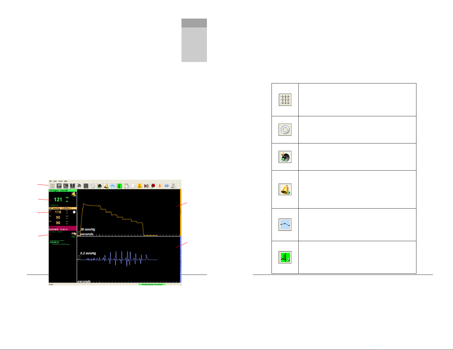
The PC-Display Screen
When the BP-AccuGard is used in conjunction with a computer, the PC-Display
software provided with each wireless monitor is the Windows program used. PC-
Display software automatically detects the particular device used. When connected
to a BP-AccuGard, the screen changes to accommodate blood pressure information
as shown below.
NOTE: Some icons on the PC-Display Toolbar are grayed out since
they do not apply to the BP-AccuGard
Chapter
2
Toolbar
Pulse Rate
BP and
Alarms
Connection
Status
Cuff Pressure
Waveform
Oscillometric
Waveform
21
Toolbar
The PC-Display Toolbar provides quick access to many of the commonly used
functions. Each button on the Toolbar uses an icon to represent the function for
which it is used. In most cases, these button needs only a single left mouse click to
activate. Some buttons allow functions to be clicked on and off. The table below
describes the icons used with the BP-AccuGard. More information about all of the
configuration options appears in the PC-Display manual.
The Grid Enable button is a toggle button that will overlay a
wire-frame grid over both the cuff pressure waveform and
oscillometric waveform. The height of each rectangle within
the grid is directly associated with the pressure marker at the
bottom left of each waveform window.
The Current Configuration button allows quick access to the
configuration of the current session. Any values that are
modified here will return to the default values upon exiting PC-
Display.
The Silence Alarms button is a toggle button. The default
setting is “enabled”, meaning that any tripped alarm will sound
the alarm tone. When disabled the alarm sound will cease
regardless of how many parameters are out of range.
The Monitor Alarms button is also a toggle button that is
enabled by factory default. When enabled, the default alarm
limits beside each measurement are displayed and a recorded
alarm event and audible alarm tone, if enabled. However,
even if those options are still enabled they will not happen if
the Monitor Alarms button is disabled.
The Trend Graph button, when clicked, will open the Trend
Graph window. For the BP-AccuGard, pulse rate and the Mean
Arterial Pressure trend curves are displayed. See the PC-
Display manual for more information about the Trend Graph
window.
The Record Episode button is a toggle button enabled by
factory default. When enabled, this button will record a
patient episode file. Parameters will not be recorded when
disabled unless the Print function is selected. See the end of
this chapter for more details.

22
The Patient Information button allows the user to change the
patient information for the current recording session. This
window also appears during initial connection.
The Review Episode button allows the user to open any of the
patient episode files recorded in the current session directly
into the reviewing software. See the end of this chapter for
more details.
The Stop/Start button is a toggle button that by default is set
to Start (play). Pressing this button will stop the waveforms on
the screen for easier viewing. Clicking the button again will
restart the trace. Measurements and data collection and
recording is not affected.
The BP Measurement button is a toggle button that is “OFF” by
default. Once enabled, the automatic measurement process
will begin provided a cuff size is selected.
The Marker button
marks the trace and automatically logs
vital signs for the event (“marker event”) if an episode is being
recorded.
The Info button opens a screen with o version information for
PC-Display as well as any connected wireless remote. This
button may only be necessary when speaking to a support
representative.
NOTE: Some Toolbar icons with toggle functionality have either a green
check mark or a red ‘x’ at the base of the icon as shown below Button has
a 3D appearance when enabled
Figure 7 Alarm audio enabled and disabled
23
Pulse Rate Display
The Pulse Rate Box shows a large number associated with the calculated average
pulse rate for the last measurement (in beats per minute). To the right of this
number are two smaller numbers corresponding to the upper and lower alarm limits
that have been set for this parameter
.
If the alarm limit Pulse Rate exceeds either of these values, an alarm event is
triggered, a red box will appear around the parameter and an alarm audio will sound
(if alarm audio is enabled). The preset alarm limits will not appear if the Monitor
Alarms button on the Toolbar is disabled. The bell in the upper right corner of the
display will have a green check mark if the Monitor Alarms button is enabled or a red
‘x’ if disabled.
Bloo Pressure Display
Calculated Average
Pulse Rate
Upper Alarm Limit
Lower Alarm Limit
Alarm Status Icon
Upper Alarm Limit
Exceeded
Measured Systolic Value
Measured Diastolic Value
Measured Mean Arterial
Pressure Value
Upper Alarm Limit
Lower Alarm Limit
Measurement Status Icon
Selected Cuff Size
24
The Display shows the last measurements for systolic (Sys), diastolic (Dia) and MAP.
The preset upper and lower alarm limits appear in smaller characters to the right of
each measurement. Like the Pulse Rate Display, pressure alarm limits are highlighted
with a red box when the alarm limit is exceeded.
The title bar for this Display contains the cuff size currently selected or the default
cuff size (#3) if not selected. The top right of this Display shows the measurement
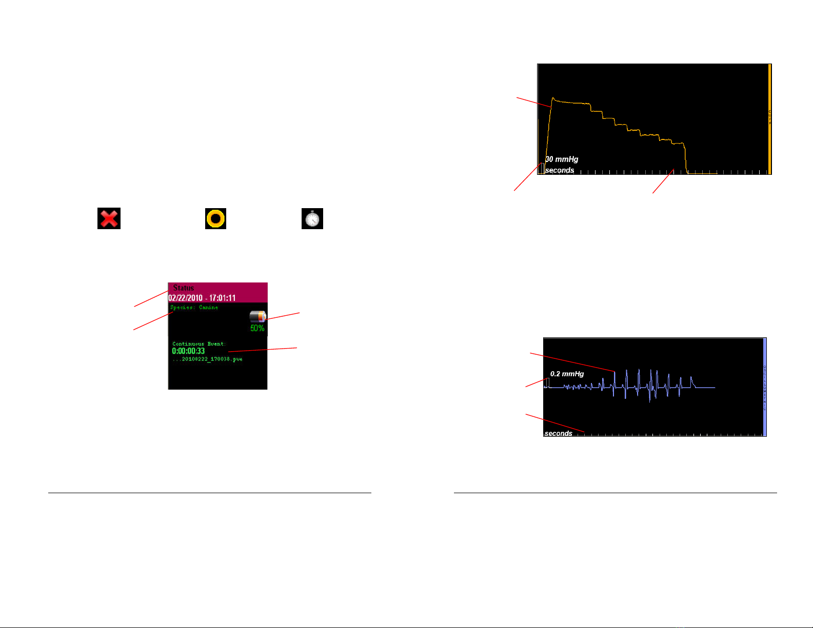
status icon. This icon will start as a large red ‘X’ to denote that the blood pressure
measurement is disabled. When a measurement begins, this icon will change to
several concentric circles moving in and out to denote that a measurement is in
progress. Once the measurement is complete, the icon will change to a stopwatch to
denote that it is in the preset interval between measurements until the next
automatic measurement occurs.
BP measurement disabled BP measurement in progress BP measurement pending
Status Display
The Status Box shows various parameters related to the current monitoring session.
The title bar shows both the current date and time. The selected species for the
patient being monitored is displayed below the date. The battery life icon,
representing BP-AccuGard battery life remaining in increments of 25%, appears at
the top right. If recording, the Status Box will show the elapsed time since the
recording began. Beneath this is the end of the file name for this recorded episode.
Current Date/Time
Selected Species
Remote Battery Level
Recording Elapsed Time
and File Name
25
Cuff Pressure Waveform Display
The Cuff Pressure Waveform Display displays a continuous graph of the cuff pressure
in mmHg. This waveform will repeat continuously as long as the BP-AccuGard is
wirelessly connected to PC-Display.
The Pressure Reference Marker indicates the vertical scale of the waveform area and
corresponds to the height of each of the grid rectangles when the grid is enabled. A
time reference scale (Seconds Reference Marker), in seconds, is displayed on the
lower edge of this display.
Oscillometric Waveform Display
Cuff Pressure
Waveform
Pressure Reference
Marker Seconds Reference Marker
Oscillometric Waveform
Pressure Reference
Marker
Seconds Reference
Marker
26
The Oscillometric Waveform Display shows a continuous graph of the oscillometric
pressure pulses of the patient’s blood vessel wall. This waveform will repeat
continuously as long as the BP-AccuGard is wirelessly connected to PC-Display.
The Pressure Reference Marker indicates the vertical scale of the waveform area and
corresponds to the height of each of the grid rectangles when the grid is enabled. A
time reference scale (Seconds Reference Marker), in seconds, is displayed on the
lower edge of this display.
The oscillometric waveform is helpful for visualizing the measurement process and
can indicate patient movement if drastic spikes are seen instead of a gradual rise and
fall of the pulse heights.
Controlling Measurements with PC-Display
NOTE: This section assumes that you have already performed the necessary Vmed
software installation and Bluetooth pairing procedures listed in the PC-Display
User’s Manual If you have not done this, please do so before proceeding.
The BP-AccuGard can perform a blood pressure measurement while connected to
PC-Display with the user controlling this process from the computer itself or from the
BP-AccuGard remote. The following steps will demonstrate how to connect to a BP-
AccuGard remote with the PC-Display software and then perform a blood pressure
measurement from the PC-Display software.
.
Press and release the BP-AccuGard power switch after the completing the
Bluetooth discovery procedure.
NOTE: Each device must be discovered once
for each computer used
The “COMPUTER” light on the BP-AccuGard will turn
red and then yellow.
2.
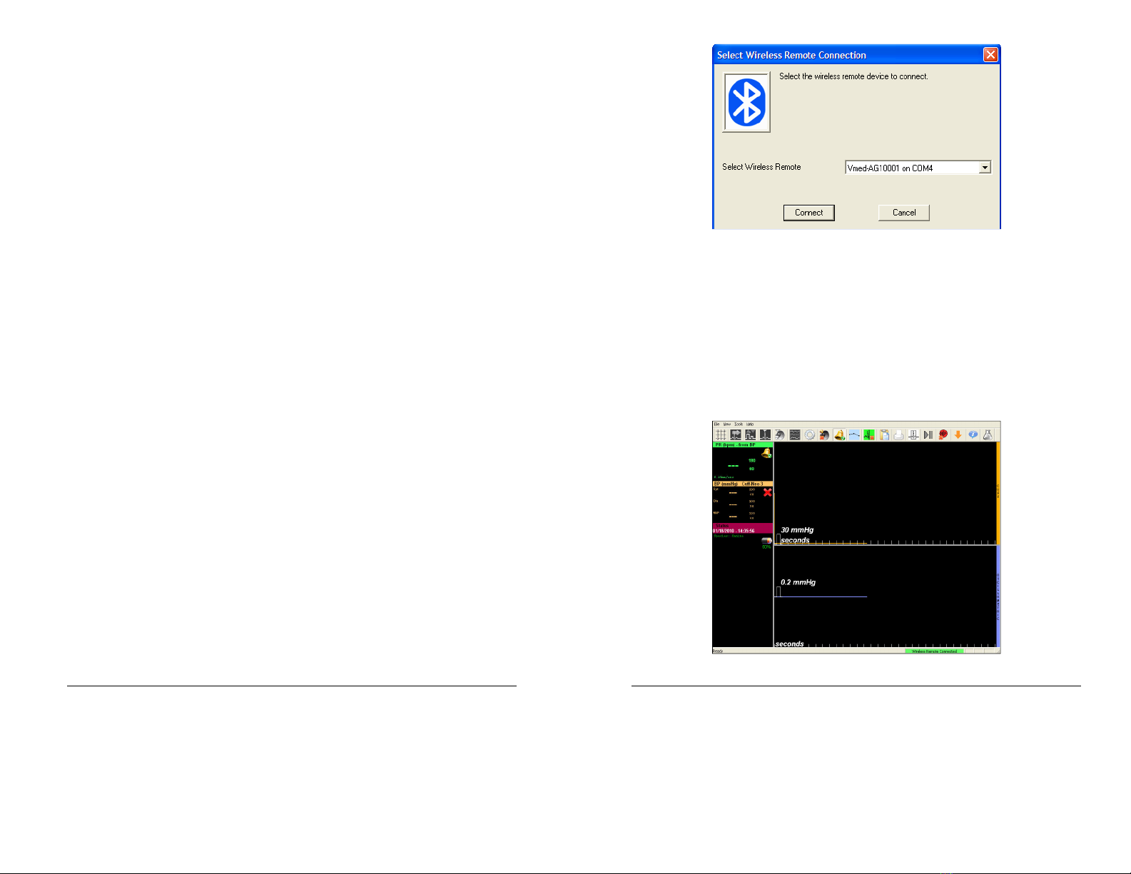
Double-click the PC-Display icon on the desktop to open the window below:
27
Figure 8 Connection window showing device ID number
Select the device you wish to use in the drop-down window and click “Connect”.
NOTE: If you have discovered multiple wireless monitors, the device last discovered
or connected to your computer will appear in the text box in the above window
Press the “down” arrow to view the other discovered devices and highlight the one
you want to use before connecting
3.
After selecting the desired ID Number from the list, press the “Connect”
button to connect to the device as shown below.
28
Wireless connection is confirmed when the “Computer” light on the device
flashes green and there are lines traversing the screen in both the “Cuff” and
“Oscillometric” waveform windows on the computer display. In addition, the
BP-AccuGard will display the following:
S
e
l
e
c
t
M
o
d
e
M
a
n
C
o
n
f
I
g
A
u
t
o
Next, connect the blood pressure hose to the rear of the BP-AccuGard by
twisting its connector onto the BP-AccuGard “AIRLINE” receptacle
.
Figure 9 Connecting airline to monitor
29
4.
Connect the blood pressure airline to a cuff of appropriate size for the patient
by twisting the hose connector onto the cuff connector.
Figure 0 Connecting cuff to airline
5.
Wrap the cuff around the leg or base of tail so that artery reference mark on
the cuff is over the vessel and falls within the range marks on the cuff when
wrapped around the limb. The cuff should not be loose around the patient. If
the artery line does not fall within the range marks, select a proper size cuff.
Figure Cuff size in range Figure 2 Cuff size too small

30
6.
After correctly fitting the cuff to the patient, click the “BP” icon on the PC-
Display Toolbar.
7.
The menu below will appear. Select the correct cuff size from this drop-down
box and then click the OK button.
8.
The blood pressure measurement will immediately begin and the animated
circular measurement status icon will appear in the Blood Pressure Display.
9.
To stop the measurement simply click on the same BP icon on the toolbar and
this will deflate the cuff immediately.
31
0.
During the measurement, the top waveform will display the cuff pressure (in
mmHg); bottom waveform will display the oscillometric pressure (in smaller
increments of mmHg). If there is no patient movement, the oscillometric
waveform will look like a series of pulses as shown below.
.
The default interval between measurements as set in PC-Display Configuration
is five minutes. During the interval between measurements, the status icon in
the Blood Pressure Display will change to an animated stopwatch icon and the
last measured values (including pulse rate) will remain in their designated
areas.

32
If you wish to change the interval between measurements, you may do so by
selecting the icon on the PC-Display toolbar and selecting the menu
show below.
NOTE: Selections will return to those set in the PC-Display
Configuration upon conclusion of the monitoring episode
Figure 3 Window to change settings for a particular patient
Controlling Measurements from the BP-AccuGar
While connected to the compute settings and measurements can be controlled from
the computer, as previously described. To also control from the BP-AccuGard, follow
these steps:
Perform steps -7 above in order to prepare the BP-AccuGard with the patient and
with PC-Display.
33
. Once you have connected the BP-AccuGard remote to PC-Display, the screen
below will appear on the unit’s display. Press the button below “BP” on the
screen.
P
C
C
o
n
n
e
c
t
e
d
M
e
n
u
R
e
c
o
r
d
B
P
2. The text on the screen will change as shown below:
P
C
C
o
n
n
e
c
t
e
d
U
p
D
o
w
n
O
K
The menu below will appear on the computer screen.

34
3. Use the soft key beneath either “Up” or “Down” on the screen to select the
desired cuff size from the pop-up menu in PC-Display.
After selecting cuff, press the soft key beneath “OK”.
P
C
C
o
n
n
e
c
t
e
d
U
p
D
o
w
n
O
K
4. The measurement cycle will begin and the LCD screen will change to the
following text:
M
e
a
s
u
r
i
n
g
.
.
.
S
T
O
P
5. At any time during the measurement, you can stop the measurement by
pressing the soft key beneath the word “STOP” and the cuff will deflate.
However, if allowed to complete, then PC-Display will show the measurements
on your computer screen. The BP-AccuGard remote will display the
measurements on its screen as shown below:
S
S
x
x
x
D
I
A
x
x
x
M
A
P
x
x
x
H
R
x
x
x
“Xxx” refers to the specific measurement. The text above will alternate with
the following until the next measurement begins.
P
C
C
o
n
n
e
c
t
e
d
M
e
n
u
R
e
c
o
r
d
B
P
The BP-AccuGard and PC-Display will continue to make blood pressure
measurements until stopped – either at the remote or from the PC- Display
screen.
35
Recor ing Measurements
One of the main reasons for using PC-Display with the BP-AccuGard is its ability to
record blood pressure measurements. Recorded data is put into a file known as a
patient episode
. Each patient episode can include the patient’s name, the client’s
name and other information pertinent to the patient, including species, breed,
weight and birth date as well as various measured vital signs data from the BP-
AccuGard.
With "AutoSave" enabled patient episode recording will begin by default each time
the BP-AccuGard is connected to PC-Display. While other Vmed wireless monitors
will record waveforms, PC-Display with the BP-AccuGard will only record vital signs in
tabular form. Pressure waveforms are not recorded. In addition to saving
measurements automatically at the interval selected (see Chapter 3), PC-Display will
also record vital signs when an alarm is triggered or if the Marker button is pressed.
The result is a table of blood pressure measurements for the entire monitoring
episode.
Refer to the PC-Display manual for more detail about recording episodes and how to
open recorded episodes with the Reviewer software.

36
Chapter 3 Configuration Options
The BP-AccuGard has several preset values including alarm limits that affect its use.
Configure settings within the device itself if used in stand-alone mode or use the
PC-Display Configuration Settings screen under the “Tools” selection when the
computer connection is used. This chapter will describe how to configure both.
Device Configuration
Perform the device configuration using the LCD screen and soft keys. Use the
following steps to view the current configuration and make changes on the device
itself.
. Turn on the BP-AccuGard by pressing and immediately releasing the red power
button on the keypad of the BP-AccuGard. Do not hold this button down
unless you wish to turn the device off.
2. The following screen will appear for 3 seconds:
V
m
e
d
T
e
c
h
n
o
l
o
g
y
,
I
n
c
.
(
c
)
2
0
1
0
3.
Then the screen will show this text for 5 seconds
:
B
P
-
A
c
c
u
G
a
r
d
w
i
t
h
B
l
u
e
t
o
o
t
h
NOTE: The bottom row will be blank if you unit is not equipped with
Bluetooth
Chapter
3
37
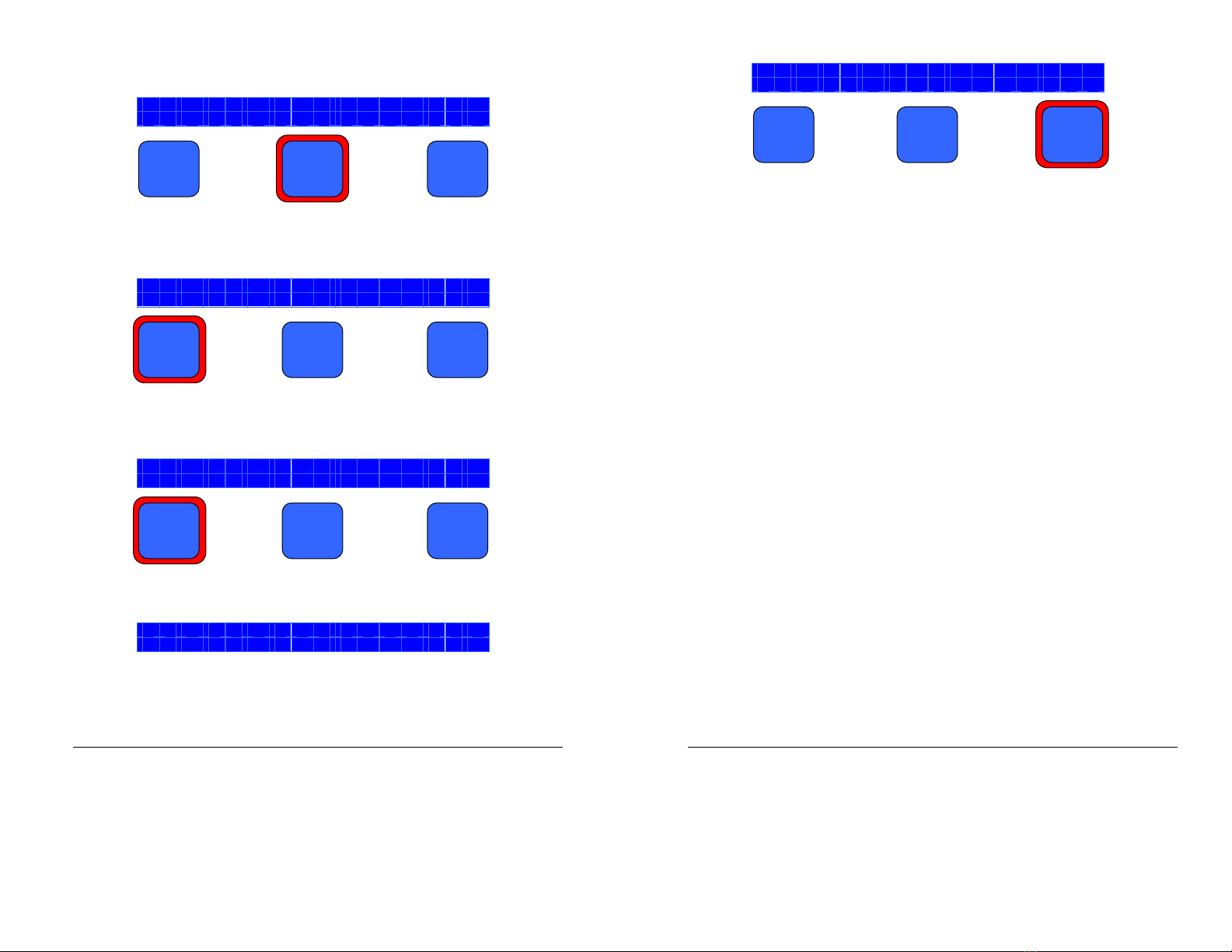
4. Finally, the screen below showing the “home” text will appear. Use the blue
buttons beneath the screen to select the option immediately above each one.
S
e
l
e
c
t
M
o
d
e
M
a
n
C
o
n
f
i
g
A
u
t
o
5. Select the button beneath “Config” to open the configuration sub-menu.
S
e
l
e
c
t
M
o
d
e
M
a
n
C
o
n
f
i
g
A
u
t
o
6.
The following screen will appear
:
z
z
z
z
z
z
z
z
z
z
z
E
d
i
t
N
e
x
t
D
o
n
e
Where “zzzzzzzzzzz” (above) represents one of the following
configuration items and xxx (below) represents the current value for
that item:
Initial mmHg xxx
Contrast xxx %
Backlight xxx %
Key Clicks xxx
Alarm SYS Hi xxx
SYS Hi Limit xxx
Alarm SYS Lo xxx
SYS Lo Limit xxx
Alarm DIA Hi xxx
DIA Hi Limit xxx
Alarm DIA Lo xxx
DIA Lo Limit xxx
Alarm MAP Hi xxx
MAP Hi Limit xxx
Alarm MAP Lo xxx
MAP Lo Limit xxx
Averaging Mo e
Battery Level
Device Status
38
7. Press the soft key beneath “Next” in order to cycle through each of the items
in the list above.
I
n
i
t
i
a
l
m
m
H
g
1
6
0
E
d
i
t
N
e
x
t
D
o
n
e
8. When you have chosen a configuration item to edit, press the soft key beneath
“Edit”.
K
e
y
C
l
i
c
k
s
O
N
E
d
i
t
N
e
x
t
D
o
n
e
9. Some items, like “Key Clicks”, have only two states, "ON" and "OFF" and one
button toggles between the two states.
K
e
y
C
l
i
c
k
s
O
N
O
n
/
O
f
f
O
K
Otherwise, an adjustment option will appear as below:
B
a
c
k
l
i
g
h
t
7
5
%
U
p
D
o
w
n
O
K
0. After editing the given configuration as desired, press the soft key beneath
“OK” to accept it and return to the previous menu.
39
B
a
c
k
l
i
g
h
t
9
0
%
U
p
D
o
w
n
O
K
. Repeat these steps for the other configuration items.
Configuration Options an what they mean
Initial mmHg xxx
This value, in mmHg, is the initial cuff inflation pressure for each measurement
before the device begins is controlled deflation cycle. Typically, this is set at
about 30 mmHg over the expected systolic blood pressure. If the cuff inflates
twice at the beginning of each measurement, set the value a bit higher.
WARNING: Do not set it too high since this could be harmful to the patient
The available range is 60 mmHg to 280 mmHg DEFAULT VALUE: 160
Contrast xxx %
The contrast, given in percent, is how much visual contrast is shown on the
screen. The available range is 0% to 00% in increments of 5%.
DEFAULT
VALUE: 50
Backlight xxx %
The backlight, given in percent determines screen brightness. The available
range is 0% to 00% in increments of 5%. Please note that battery life
between charges will decrease with higher backlight settings.
DEFAULT
VALUE: 75
Key Clicks xxx
When the “Key Clicks” option is set to “ON”, a very short beep or click will
sound.
DEFAULT VALUE: ON
Alarm SYS Hi xxx
The “Alarm SYS Hi” setting is a toggle to turn the Systolic High alarm “ON” or
“OFF”. If set to “ON”, the alarm is active and the pressure value set in the “SYS
Hi Limit” option will be displayed. The available range for systolic high limits is
Table of contents
Other Vmed Technology Blood Pressure Monitor manuals


